
Subscribe to Our Youtube Channel
Related Manuals for Smartgen HMU8-860


Summary of Contents for Smartgen HMU8-860
- Page 1 HMU8-860 ATS REMOTE MONITORING CONTROLLER USER MANUAL SMARTGEN (ZHENGZHOU) TECHNOLOGY CO., LTD.
- Page 2 SmartGen Technology at the address above. Any reference to trademarked product names used within this publication is owned by their respective companies. SmartGen Technology reserves the right to change the contents of this document without prior notice. Table 1 – Software Version Date...
- Page 3 Indicates a procedure or practice, which, if not strictly observed, could result in CAUTION! damage or destruction of equipment. Indicates error operation may cause death, serious injury and significant property damage. WARNING! HMU8-860 ATS Remote Monitoring Controller User Manual Page 3 of 50...
-
Page 4: Table Of Contents
OUTPUT PORTS FUNCTION DESCRIPTION ................44 6.3.3 CUSTOM COMBINED OUTPUT ....................48 INSTALLATION ............................49 HUM8-860 FIXING CLIPS ........................ 49 OVERALL DIMENSION AND PANEL CUTOUT ................49 TROUBLESHOOTING ..........................50 HMU8-860 ATS Remote Monitoring Controller User Manual Page 4 of 50... -
Page 5: Overview
OVERVIEW HMU8-860 ATS Remote Monitoring Controller adopts high-performance ARM chip, large, high-resolution capacitive touch screen with Chinese and English display, which can realize remote control, data monitoring and parameter configuration of HAT860 medium voltage ATS controller via RS485 interface. It has compact structure, easy operation and reliable running. -
Page 6: Performance And Characteristics
PERFORMANCE AND CHARACTERISTICS HMU8-860 ATS remote monitoring controller (hereinafter called monitoring module) is used for the remote data monitoring and control of HAT860 MV-ATS controller (hereinafter called master control module). The two modules communicate via RS485 interface. Main features are the followings: ─... -
Page 7: Specification
Working Humidity (20~93)%RH Storage Temperature (-30~+80)°C Front Panel: IP65, when a waterproof rubber ring is installed Protection Level between the controller and the panel. Rear Panel: IP20 Weight 1.3kg HMU8-860 ATS Remote Monitoring Controller User Manual Page 7 of 50... -
Page 8: Display And Operation
It is extinguished when the communication is abnormal. It is always illuminated when controller is powered on and in operation; Power It is extinguished when controller stops working. HMU8-860 ATS Remote Monitoring Controller User Manual Page 8 of 50... -
Page 9: Display Interface And Opertion
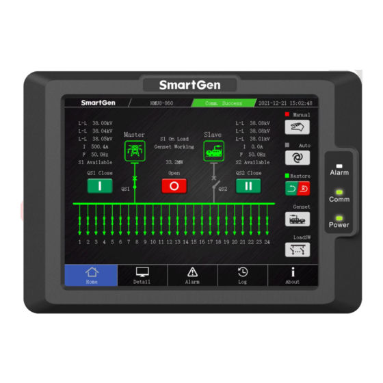
Power icon is shown in green when the power is normal, otherwise it is Incoming Status Area gray; It is shown in green when ATS and load breaker are available, otherwise it is gray. HMU8-860 ATS Remote Monitoring Controller User Manual Page 9 of 50... - Page 10 Genset Press it to enter into genset operation page. Load Switch Press it to enter into load manual switch page. HMU8-860 ATS Remote Monitoring Controller User Manual Page 10 of 50...
-
Page 11: Genset Operation Display
Icon Description Start Press it to manually control corresponding genset to start. Stop Press it to manually control corresponding genset to stop. Return Press it to return to homepage. HMU8-860 ATS Remote Monitoring Controller User Manual Page 11 of 50... -
Page 12: Load Stepwise Switch Display
Page Up Press it to adjust load breaker display items forward. Page Down Press it to adjust load breaker display items backward. Return Press it to return to homepage. HMU8-860 ATS Remote Monitoring Controller User Manual Page 12 of 50... -
Page 13: Detailed Information Display
The detailed information interface displays S1 electric parameters (includes phase voltage, line voltage, current, phase sequence, frequency information), S2 electric parameters, load power information, total supply time and power. 4.2.5 ALARM DISPLAY Fig. 6 – Alarm Display Interface HMU8-860 ATS Remote Monitoring Controller User Manual Page 13 of 50... - Page 14 In auto mode, if QTIE close signal can’t be detected after close QTIE Close Failure output delay, QTIE close failure alarm will be initiated. HMU8-860 ATS Remote Monitoring Controller User Manual Page 14 of 50...
- Page 15 When earth current detection is enabled and the current is greater Earth Fault than the set value, warning alarm will be initiated when the action is selected. HMU8-860 ATS Remote Monitoring Controller User Manual Page 15 of 50...
-
Page 16: Event Log Display
200 event records can be viewed circularly. Click log serial number, it will display the detailed information of current log, which is shown as following: Fig.8 – Detailed Information Display of Event Log HMU8-860 ATS Remote Monitoring Controller User Manual Page 16 of 50... - Page 17 S1 PT break Warning Event S2 PT break Input 1-6 comm. Failure warning Ouput 1-3 comm. failure warning Load switching failure Earth fault warning Fault Event QS1 close failure HMU8-860 ATS Remote Monitoring Controller User Manual Page 17 of 50...
-
Page 18: About Display
QTIE breaker trip alarm Load breaker trip alarm 4.2.7 ABOUT DISPLAY Fig.9 – About Display Interface The about display interface includes hardware information, the version of hardware and software, HMU8-860 ATS Remote Monitoring Controller User Manual Page 18 of 50... -
Page 19: Parametr Configuration
4.3 PARAMETR CONFIGURATION In the “About” interface, press key to enter the module selection page and select the module that needs parameters configuration. Fig.10 – Module Selection Interface HMU8-860 ATS Remote Monitoring Controller User Manual Page 19 of 50... -
Page 20: Parameter Configuration Of Monitoring Module
After the parameter configuration, press the exit key to pop up the parameter saving dialog box and save according to the prompts. 4.3.2 PARAMETER CONFIGURATION OF MASTER CONTROL MODULE Fig.12 – Parameter Configuration Interface of Master Control Module HMU8-860 ATS Remote Monitoring Controller User Manual Page 20 of 50... -
Page 21: Advanced Parameter Configuration
HAT860 master control module, HMU8-860 default factory value, standard value and remove UI resource. Part of the items need to enter a specific password to access, if necessary, please contact the manufacturer. -
Page 22: Wiring
It is recommended to use twisted shielding wire RS485-2 with 120Ω impedance, whose single end is B(-) 0.5mm grounded. Short connect terminal 12 and 14 and 0.5mm A(+) connect 120Ω terminal resistor. HMU8-860 ATS Remote Monitoring Controller User Manual Page 22 of 50... -
Page 23: Connection Diagram Of Hum8-860 And Hat860
5.2 CONNECTION DIAGRAM OF HUM8-860 AND HAT860 HAT860 master control module connects RS485-1 interface, HUM8-860 monitoring module conntects RS485-2 interface. Fig.14 – Connection Diagram of Monitoring Module and Master Control Module HMU8-860 ATS Remote Monitoring Controller User Manual Page 23 of 50... -
Page 24: Scopes And Definitions Of Programmable Parameters
1: 4800bps (0-3) Rate 2: 9600bps 3: 19200bps 0: None RS485-3 Parity Bit (0-2) 1: Odd Parity 2: Even Parity 1: 1 Bit RS485-3 Stop Bit (1-2) 2: 2 Bits HMU8-860 ATS Remote Monitoring Controller User Manual Page 24 of 50... -
Page 25: Parameter Contents And Scopes Of Master Control Module
2: S1 Mains S2 Mains; 3: S1 Gen S2 Gen. 0: 3 Phase 4 Wire (3P4W) AC System (0~3) 1: 3 Phase 3 Wire (3P3W) 2: 2 Phase 3 Wire (2P3W) HMU8-860 ATS Remote Monitoring Controller User Manual Page 25 of 50... - Page 26 Reverse Phase Seq. (0~1) 0: Disable 1: Enable Breaker Setting Auto 0: Auto Transfer Non-restore; (0~1) Transfer/Restore 1: Auto Transfer/Restore. HMU8-860 ATS Remote Monitoring Controller User Manual Page 26 of 50...
- Page 27 When the genset is ready to stop, stop delay begins, after the delay has Stop Delay (0-9999)s expired, start signal will disconnected. Two Gensets Start 0: Cycle Run; (0~3) Mode 1: Master-Slave Run; HMU8-860 ATS Remote Monitoring Controller User Manual Page 27 of 50...
- Page 28 The date of start the genset monthly. Sunday Monday Tuesday Run Time (Week) Mon ~ Sun Sunday Wednesday Thursday Friday Saturday Run Time (Hour) (0~23)h The time of genset start. Run Time (Minute) (0~59)min HMU8-860 ATS Remote Monitoring Controller User Manual Page 28 of 50...
- Page 29 It’s the delay time before the load disconnect or switch transfer. Used for Elevator Delay (0~300)s control the running elevator stop at the nearest floor until the switch transfer is terminated. HMU8-860 ATS Remote Monitoring Controller User Manual Page 29 of 50...
- Page 30 Earth Fault Detect (0~3600)s Delay Value removed. 0: No Action 1: Warning Alarm Earth Fault Action (0~2) 2: Fault Alarm HMU8-860 ATS Remote Monitoring Controller User Manual Page 30 of 50...
- Page 31 0: Close to activate; Active Type (0~1) 1: Open to activate. Digital Input 13 (0~159) Not Used. 0: Close to activate; Active Type (0~1) 1: Open to activate. Relay Outputs Setting HMU8-860 ATS Remote Monitoring Controller User Manual Page 31 of 50...
- Page 32 Relay Output 13 (0~1) 0: Output (NO) 1: Output (NC) Active Type Contents Setting (0~159) Not Used. Combined 1 or Out (0~1) 0: Output (NO) 1: Output (NC) 1 Active Type HMU8-860 ATS Remote Monitoring Controller User Manual Page 32 of 50...
- Page 33 0: Output (NO) 1: Output (NC) 2 Active Type Combined 4 or Out (0~159) Not Used. 2 Contents Combined 4 and (0~1) 0: Output (NO) 1: Output (NC) Out Active Type HMU8-860 ATS Remote Monitoring Controller User Manual Page 33 of 50...
- Page 34 2: Auto Mode. RS485 communication address. Press synchronization key, this parameter of monitoring module and Module Address (1~254) master control mosule can be set simultaneously without affecting following communication. HMU8-860 ATS Remote Monitoring Controller User Manual Page 34 of 50...
- Page 35 Date and Time Controller (0~20) Information displayed “About” Description 1 characters interface. Controller (0~20) Any characters can be inputted via PC Description 2 characters software (letter occupies 1 character, HMU8-860 ATS Remote Monitoring Controller User Manual Page 35 of 50...
- Page 36 Open Control (0~1) When it is enabled, it can control the stepwise open of load breaker. 0: No Action; Stepwise Switch (0~2) 1: Warning Alarm; Failure Action 2: Fault Alarm. HMU8-860 ATS Remote Monitoring Controller User Manual Page 36 of 50...
- Page 37 Expand Output Modules (1-3) Setting 0: Disable 1: Enable Enable (0~1) When it is enabled, it can communicate with DOUT16B-2 module. Comm. Fail Action (0~1) 0: Warning Alarm 1: Fault Alarm HMU8-860 ATS Remote Monitoring Controller User Manual Page 37 of 50...
-
Page 38: Digital Input/Output Function Description
Lamp Test the LCD is illuminated while the LCD screen is all black. In cycle start, if the input is active, S1 Gens start will be Gen1 Fault Input inhibited. HMU8-860 ATS Remote Monitoring Controller User Manual Page 38 of 50... - Page 39 Simulate S1 voltage is normal; the S1 voltage abnormal delay Simulate S1 OK is deactivated. Simulate S2 voltage is normal; the S2 voltage abnormal delay Simulate S2 OK is deactivated. HMU8-860 ATS Remote Monitoring Controller User Manual Page 39 of 50...
- Page 40 Load 3 Breaker Trip Load breaker 3 trip fault input. Load 4 Close Status Load breaker 4 closed status input. Load Work Position Load breaker 4 work position status input. Status HMU8-860 ATS Remote Monitoring Controller User Manual Page 40 of 50...
- Page 41 Load breaker 12 closed status input. Load 12 Work Position Load breaker 12 work position status input. Status Load Test Position Load breaker 12 test position status input. Status HMU8-860 ATS Remote Monitoring Controller User Manual Page 41 of 50...
- Page 42 Position Load breaker 19 test position status input. Status Load 19 Breaker Trip Load breaker 19 trip fault input. Load 20 Close Status Load breaker 20 closed status input. HMU8-860 ATS Remote Monitoring Controller User Manual Page 42 of 50...
- Page 43 QTIE Close Key Input in manual mode. When bustie control is enabled, it controls QTIE breaker open QTIE Open Key Input in manual mode. Reserved Reserved Reserved Reserved Reserved Reserved HMU8-860 ATS Remote Monitoring Controller User Manual Page 43 of 50...
-
Page 44: Output Ports Function Description
Output when the genset is in Auto mode. Manual Mode Output when the genset is in Manual mode. Genset Start Control the genset to start. Reserved QS1 Close Control Control the QS1 to close. HMU8-860 ATS Remote Monitoring Controller User Manual Page 44 of 50... - Page 45 S1 Under Volt S1 Over Freq S1 power supply status. S1 Under Freq S1 Loss of Phase Reverse Phase Sequence Reserved Reserved S2 Blackout S2 power supply status. S2 Over Volt HMU8-860 ATS Remote Monitoring Controller User Manual Page 45 of 50...
- Page 46 Expand output control way, load breaker 4 open output. Load 5 Close Output Expand output control way, load breaker 5 close output. Load 5 Open Output Expand output control way, load breaker 5 open output. HMU8-860 ATS Remote Monitoring Controller User Manual Page 46 of 50...
- Page 47 Load 24 Close Output Expand output control way, load breaker 24 close output. Load 24 Open Output Expand output control way, load breaker 24 open output. Reserved Reserved Reserved Reserved Reserved HMU8-860 ATS Remote Monitoring Controller User Manual Page 47 of 50...
-
Page 48: Custom Combined Output
3 inactive, defined combination output is not outputting; When input port 1 inactive and input port 2 inactive, whatever input port 3 is active or not, defined combination output is not outputting. HMU8-860 ATS Remote Monitoring Controller User Manual Page 48 of 50... -
Page 49: Installation
Care should be taken not to over tighten the screws of fixing clips, the torque is 2.75 kgf.cm (0.27 ─ N.m). 7.2 OVERALL DIMENSION AND PANEL CUTOUT Unit: mm Fig. 15 – Overall Dimension and Panel Cutout HMU8-860 ATS Remote Monitoring Controller User Manual Page 49 of 50... -
Page 50: Troubleshooting
Check RS485’s A and B connection is reversely connected or not; Check whether the RS485 conversion module is damaged or not; Check RS485 communication port is damaged or not. _________________________________ HMU8-860 ATS Remote Monitoring Controller User Manual Page 50 of 50...
Need help?
Do you have a question about the HMU8-860 and is the answer not in the manual?
Questions and answers