Rice Lake IQ plus 2100 Installation Manual
Hide thumbs
Also See for IQ plus 2100:
- Installation manual (43 pages) ,
- Installation manual (42 pages)
Table of Contents
Advertisement
Quick Links
Download this manual
See also:
Installation Manual
Advertisement
Table of Contents

Related Manuals for Rice Lake IQ plus 2100


Summary of Contents for Rice Lake IQ plus 2100
- Page 1 IQ plus 2100 ® Digital Bench Scale Version 1.0 Installation Manual 53415...
-
Page 3: Table Of Contents
Course descriptions and dates can be viewed at www.rlws.com or obtained by calling 715-234-9171 and asking for the training department. © 2003 Rice Lake Weighing Systems. All rights reserved. Printed in the United States of America. Specifications subject to change without notice. - Page 4 RL2100 Bench Scale ............. 34 IQ plus 2100 Limited Warranty ......................35...
-
Page 5: About This Manual
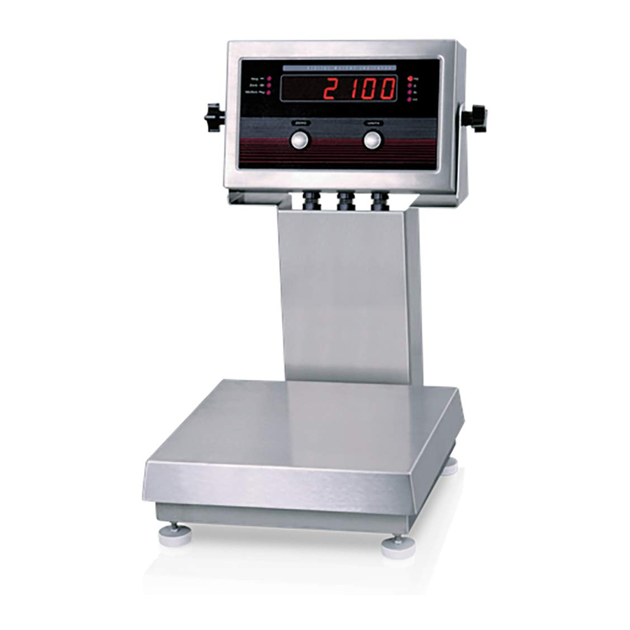
Introduction Operating Modes The IQ plus 2100 digital bench scale consists of an IQ plus 210 digital weight indicator and an RL2100 bench The IQ plus 210 has two modes of operation: scale. The indicator can be mounted to the bench scale... -
Page 6: Front Panel
IQ plus 2100 Installation Manual... -
Page 7: Installation
Installation Factory Setup The IQ plus 2100 digital bench scale is designed for easy setup and installation. All models are preconfigured and The IQ plus 2100 is preconfigured and weight weight calibrated before shipment, with the load cell calibrated at the factory before shipment. Table 2-1 lists connected to the indicator. -
Page 8: Configuration
EDP command set. Figure 3-1. Sample Revolution Display Revolution supports both uploading and downloading of indicator configuration data. This capability allows configuration data to be retrieved from one indicator, edited, then downloaded to another. IQ plus 2100 Installation Manual... -
Page 9: Front Panel Configuration
3.1.3 Front Panel Configuration The IQ plus 210 indicator can be configured using a series of menus accessed through the indicator front panel when the indicator is in setup mode. Table 3-1 summarizes the functions of each of the main menus. Menu Menu Function CONFIG... - Page 10 RIGHT ENTER RIGHT RIGHT RIGHT Value 1 Value 2 Value 3 Value 4 RIGHT Press at any parameter value to select the value and return to the parameter prompt ENTER Figure 3-3. General Menu Structure IQ plus 2100 Installation Manual...
-
Page 11: Menu Navigation
ZERO UNITS Menu Navigation Serial Menu Example (ENTER) (RIGHT) CONFIG XXXXXXX FORMAT CALIBR SERIAL XXXXXXX DIG IN DEFLT VERS RIGHT RIGHT RIGHT RIGHT When displaying last ENTER parameter prompt, press to return to the RIGHT first-level menu prompt RIGHT RIGHT RIGHT BITS TERMIN... -
Page 12: Menu Structures And Parameter Descriptions
Maximum legal value varies depending on local regulations. If OFF is selected, ZTRKBN should also be set to OFF. Table 3-2. Configuration Menu Parameters IQ plus 2100 Installation Manual... -
Page 13: Format Menu
CONFIG Menu Parameter Choices Description OVRLOA FS+2% Overload. Determines the point at which the display blanks and an out-of-range error FS+1D message is displayed. Maximum legal value varies depending on local regulations. FS+9D FILTER Digital filtering. Selects the digital filtering rate used to reduce the effects of mechanical vibration from the immediate area of the scale. - Page 14 Alternate units. Determines which units are displayed when the UNITS button is pressed. The value for the primary unit (selected on the PRIMAR parameter) is always ON. NOTE: The LB/OZ setting is not a Legal-for-Trade setting. LB/OZ Table 3-3. Format Menu Parameters IQ plus 2100 Installation Manual...
-
Page 15: Calibration Menu
3.2.3 Calibration Menu See Section 4.0 on page 20 for calibration procedures. CONFIG FORMAT CALIBR SERIAL XXXXXXX DIG IN XXXXXXX DEFLT VERS WZERO WVAL WSPAN REZERO *CAL* CAL* *CAL* Display and edit Display and edit Press Enter to test weight value Display and edit span calibration remove offset from... -
Page 16: Serial Menu
(including minus sign, if required) followed by lb and a space; and yyyy is the four-digit ounce weight (including decimal point) followed by oz. Table 3-5. Serial Menu Parameters IQ plus 2100 Installation Manual... -
Page 17: Digital Input Menu
3.2.5 Digital Input Menu CONFIG FORMAT CALIBR SERIAL XXXXXXX DIG IN XXXXXXX DEFLT VERS DIGIN1 DIGIN2 ZERO ZERO UNITS UNITS PRINT PRINT Figure 3-10. Digital Input Menu DIG IN Menu Parameter Choices Description Level 2 submenus DIGIN1 Specifies the function activated by digital inputs 1 and 2. DIGIN2 ZERO UNITS... -
Page 18: Calibration
When done, press to go to the above, or press to edit the value again, RIGHT RIGHT starting with the leftmost digit. prompt. WSPAN Figure 4-2. Editing Procedure for Numeric Values IQ plus 2100 Installation Manual... -
Page 19: Edp Command Calibration
Revolution Calibration 6. The rezero function is used to remove a ™ calibration offset when hooks or chains are To calibrate the indicator using Revolution, the used to hang the test weights. indicator must be in setup mode with the EDP port •... -
Page 20: Edp Commands
Changes to the parameters are saved as they are entered but typically do not take effect until you exit setup mode. For example, to set the motion band parameter to 5, type the following: MOTBAND=5D<ENTER> IQ plus 2100 Installation Manual... - Page 21 Command Description Values GRADS Graduations 1–10 000 ZTRKBND Zero track band OFF, 0.5D, 1D, 3D ZRANGE Zero range 1.9%, 100% MOTBAND Motion band 1D, 2D, 3D, 5D, 10D, 20D, OFF OVRLOAD Overload FS+2%, FS+1D, FS+9D, FS FILTER Digital filtering 1, 2, 4, 8, 16, 4RT, 8RT, 16RT Table 5-3.
-
Page 22: Normal Mode Commands
file. Communication between the PC and indicator will be lost once the indicator receives settings for baud rate (BAUD parameter) or data bits and parity (BITS parameter) that do not match those configured for the PC. IQ plus 2100 Installation Manual... -
Page 23: Setup And Service Information
Setup and Service Information This section describes setup and service procedures for the IQ plus 2100 digital bench scale, including installation and maintenance information, replacement parts lists, and assembly drawings. See Sections 2.1 through 2.5 for IQ plus 210 indicator information; see Sections 6.6 and 6.7 for bench scale information. -
Page 24: Load Cells
ON position. If 2.For 6-wire connections, remove jumpers JP1 and JP2. the +EXC measurements are < 5% greater (or are less) than the –EXC measurements, set the Table 2-1. J5 Pin Assignments jumper in the OFF position. IQ plus 2100 Installation Manual... -
Page 25: Serial Communications
Board Removal 2.2.4 Serial Communications To attach serial communications cables, connect If you must remove the IQ plus 210 CPU board, use the communications cables to connector J7 as shown in following procedure: Table 2-2. Use cable ties to secure serial cable to the 1. -
Page 26: Iq Plus 210 Replacement Parts
100 mA TR5 subminiature fuses (2), 230 VAC For protection against risk of fire, replace fuses only with same type and rating fuse. Caution See Section 6.4 on page 27 for complete fuse specifications. Table 2-3. Replacement Parts IQ plus 2100 Installation Manual... - Page 27 9/10X 24/8X 35/2X See Line Filter Ground Post Assembly Figure 2-4. IQ plus 210 Backplate Assembly Setup and Service Information...
- Page 28 To backplate ground post 1/3X/A To line filter 20/4X/B Setup switch connection to J1 on CPU board AC input to To power cord CPU board J8 Figure 2-6. Line Filter Assembly Figure 2-7. Ground Post Assembly IQ plus 2100 Installation Manual...
- Page 29 34/2X To J4 on CPU board To J6 on CPU board 7/2X 6/2X 5/2X Figure 2-8. IQ plus 210 Enclosure and Overlay Setup and Service Information...
-
Page 30: Bench Scale Maintenance
Upper Load Cell Platter Screws Spider Plate Upper Shim Corner Overload Protection Screw (one in each corner) Load Cell Bubble Level Lower Shim Lower Load Cell Screws Overload Protection Set Screw Figure 6-9. RL2100 Components (Side View) IQ plus 2100 Installation Manual... -
Page 31: Bench Scale Adjustments
6.6.2 Bench Scale Adjustments • Overload Protection Set Screw Elevate the scale base to allow sufficient clearance The RL2100 bench scale uses a number of screws to to adjust the set screw, then center a load equal to provide overload and underload protection for the load 125% of scale capacity on the platter. -
Page 32: Rl2100 Replacement Parts
Tilt Stand Assembly Parts Number Description (Quantity) 29635 Tilt stand (1) 42149 Tilt stand feet (4) 15144 Nylon washers, 1/4x1x1/16 (2) 30342 Wing knobs (2) Table 6-6. Tilt Stand Assembly (see Figure 6-13 on page 30) IQ plus 2100 Installation Manual... - Page 33 7/2X 17/2X 8/4X/B 9/4X 10/6X/C 14/4X 15/4X 18/2X Figure 6-12. RL2100 Bench Scale Assembly...
- Page 34 3/2X 4/2X 2/4X Figure 6-13. RL2100 Tilt Stand Assembly 8/2X 7/2X 5/2X 6/2X 4/2X 3/2X Figure 6-14. RL2100 Attachment Bracket Assembly IQ plus 2100 Installation Manual...
- Page 35 6/2X 7/2X 4/2X 5/2X 2/2X 3/2X Figure 6-15. RL2100 Column Assembly...
-
Page 36: Appendix
LED display. Error conditions can also be checked remotely by using the XE EDP command as described in Section 6.1.2. Error Message Description Solution E A/D A/D physical error Call Rice Lake Weighing Systems (RLWS) Service. EEEROM EEPROM physical error EVIREE Virgin EEPROM Use the DEFLT menu to restore defaults, then recalibrate load cells. EPCKSM... -
Page 37: Status Messages
O = Over/under range Weight data: 7 digits, right-justified, with decimal point, leading zero suppression. Overload = ^^^^^^^ Underrange = ] ] ] ] ] ] ] Display overflow = OVERFL Figure 6-1. Continuous Output Data Format IQ plus 2100 Installation Manual... -
Page 38: Specifications
Specifications Enclosure Enclosure Dimensions 9.5 in x 6 in x 2.75 in 6.4.1 IQ plus 210 Indicator 24 cm x 15 cm x 7 cm Weight 6.1 lb (2.8 Kg) Power Rating/Material NEMA 4X/IP66, stainless steel Line Voltages 115 or 230 VAC Frequency 50 or 60 Hz Approvals... -
Page 39: Iq Plus 2100 Limited Warranty
IQ plus 2100 Limited Warranty Rice Lake Weighing Systems (RLWS) warrants that all RLWS equipment and systems properly installed by a Distributor or Original Equipment Manufacturer (OEM) will operate per written specifications as confirmed by the Distributor/OEM and accepted by RLWS. All systems and components are warranted against defects in materials and workmanship for two years.
Need help?
Do you have a question about the IQ plus 2100 and is the answer not in the manual?
Questions and answers