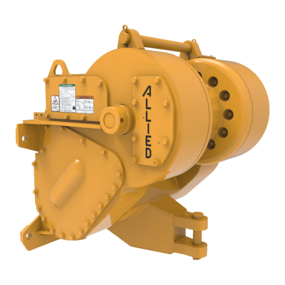
Allied Systems W8L Service Manual
Power controlled & electronic controlled towing winch
Hide thumbs
Also See for W8L:
- Operating manual (74 pages) ,
- Service manual (36 pages) ,
- Quick start manual (2 pages)

Related Manuals for Allied Systems W8L


Summary of Contents for Allied Systems W8L
- Page 1 Please check the Allied Systems website regularly for updates to this manual. www.alliedsystems.com CUSTOMER EDITION P/N 599033W Printed in U.S.A. 5/07/2018...
- Page 2 NOTE: This publication may be translated to different languages for sole purpose of easy reference in non-English speaking locations. Should there be differences in interpretations to the text, please refer to the English language edition published by Allied Systems Company as the controlling document.
-
Page 3: Safety Summary
Safety Summary Safety Summary General Safety Notices Safety Regulations Each country has its own safety legislation. It is in the The following pages contain general safety warnings operator’s own interest to be conversant with these which supplement specific warnings and cautions regulations and to comply with them in full. - Page 4 Safety Summary » If the wire rope and ferrule must be removed from the drum, make sure the end of the wire rope and ferrule are controlled when the ferrule is released. The end of the wire rope can suddenly move from the drum like a compressed spring when the ferrule is released, and cause an injury.
- Page 5 Safety Summary • Make sure ground personnel are in plain view of the • Keep yourself informed of any applicable codes, operator, and at a distance of at least 1½ times the regulations and standards for the job. working length of the wire rope. •...
- Page 6 When ordering replacement parts, give the unit serial number, part number, name of part and quantity required. For any further information on parts, service or ordering, consult your local winch dealer, or contact Allied Systems Company: Allied Systems Company 21433 SW Oregon Street Sherwood, OR 97140 U.S.A.
-
Page 7: Table Of Contents
Contents Contents Safety Summary ............i Preparation ............2-14 Pressure Gauges ..........2-14 Section 1: General ..........1-1 Brake Pressure Check ........2-14 Introduction ...............1-1 Cooling Oil Pressure Check .......2-14 Description ...............1-1 Accumulator Pressure Check ......2-16 Unit Identifi cation ..........1-2 Forward Clutch Pressure Check and Forward Installation Drawings by Tractor ......1-4 Modulator Valve Check/Adjustment ....2-16 Serial Number Codes ..........1-5... - Page 8 Contents Contents (continued) Troubleshooting ............3-29 Clutch Shaft Removal & Disassembly ....4-12 Troubleshooting Analysis Check Chart Ratios #1 - #7.............4-14 for Operators ............3-29 Ratios # 8 - #10..........4-16 Troubleshooting Analysis Check Chart Oil Clutch Disassembly ...........4-20 for Service Personnel ........3-31 Brake Shaft Removal ..........4-22 Troubleshooting Chart Intermediate Shaft Removal, Freespool ....4-24 for Electronic Control Module ......3-35...
- Page 9 Notes Notes...
- Page 10 Notes Notes viii...
-
Page 11: Section 1: General
The W8L winch has a rated line pull capacity of 355,480 N (80,000 lbf) when there is one layer of wire rope on Section 3. Electronic Controls focuses on the system the drum. -
Page 12: Unit Identifi Cation
General Unit Identifi cation Allied Winch S/N Nameplate Data For Tractor Mountings 1555 Manufactured By Vehicle Code A = Allied Systems Company See Figure 1-2 (no "A" = Hyster Company) Winch Model Sequence Number W8L = Standard K8L = Special Design (Contact Factory) - Page 13 ® Section 1 Figure 1-2 Tractor Identification and Gear Ratio (continued) Tractor Make Model and Starting Tractor Serial Number Where Applicable Fiat-Hitachi/ Caterpillar Terex Dresser Komatsu Zoomlion New Holland 20 DD 983 S/N 38K, D85E-21, D7R, D7H PS D85P-21 ...
- Page 14 Notes: 1. This list is for operators to keep track of necessary information of their winch installation drawings by tractors. If any of the installation drawings listed above is needed, please contact the Service Department of Allied Systems Company. Figure 1-3...
-
Page 15: Serial Number Codes
Section 1 Serial Number Codes The serial number codes are described on pages 1-2 and 1-3 of this manual. The nameplate with the serial number code is found on the top left hand side of the winch case. The serial number code is also stamped on the left hand side of the winch frame. -
Page 16: Warning And Maintenance Decals
General Warning and Maintenance Decals The unit nameplate, a Warning Decal and a Maintenance been damaged, install a new one in the location shown. Plate are located on the winch as shown in Figure 1-5. If the nameplate has been damaged, obtain a new one Decals are used on both sides of the winch frame as and install the new nameplate in the location shown in the shown. -
Page 17: Gear Train
Section 1 Gear Train (Ratios #1 - #7) The gear train (Figure 1-6) consists of: Torque transfer during operation is shown in Figure 1-7. a PTO shaft assembly NOTE: PTO rotation direction is determined by a clutch shaft assembly standing behind tractor and looking forward at the PTO shaft entering the winch case. -
Page 18: Operation And Control
General BRAKE LINE NORMAL BRAKE OPERATION BRAKE FREESPOOL LINE LINE NORMAL OPERATION FREESPOOL BRAKE CONTROL FREESPOOL READ OPERATING INSTRUCTIONS 271731W LINE FREESPOOL CONTROL READ OPERATING INSTRUCTIONS 271731W Power Control Lever Freespool Lever (Optional) Figure 1-8 Typical Winch Power Controls Operation and Control Description of Operations Power Controls BRAKE-OFF is the only detented position on the... - Page 19 Section 1 NOTE: Inching rapidly increases the temperatures of Inching (LINE-OUT). This operation will release the brake the clutch, the brakes and the oil, and will accelerate as the reverse clutch is applied. This permits the weight of clutch and brake wear. the load, with assistance from the reverse clutch, to unwind wire rope from the winch drum against the resistance of Inching (LINE-IN).
- Page 20 General The FREESPOOL arrangement allows mechanical control lever. When the FREESPOOL control lever is disengagement of the drum gear from the remainder of the moved to the FREESPOOL position, the sliding sleeve gear train. When the FREESPOOL control lever is shifted, disengages the drum pinion gear from the intermediate the dental clutch engages or disengages the drum pinion gear.
-
Page 21: Capacities & Specifi Cations
Section 1 Capacities and Specifi cations Recommended Oil List Recommended Oils* - General Conditions Ambient Temperature Range Manufacturer Oil Type °F °C ExxonMobil Mobil Fluid 424 (Factory fill) -13 to 104 -25 to 40 ™ Caterpillar Multipurpose Tractor Oil (MTO) -13 to 104 -25 to 40 Recommended Oils* - Low Temperature Conditions... -
Page 22: Torque Specifi Cations
General Torque Specifi cations NOTE: Unless otherwise specifi ed, torque: NOTE: All torque values given with threads lubricated. 1/2 UNC to 50 ft-lbs (7 kg-m) 3/8 UNC to 25 ft-lbs (4 kg-m) ITEM ft-lbs kg-m PTO Shaft Assembly Bearing Carrier Capscrews Clutch Shaft Assembly Bearing Retainer Capscrews Bearing Locknut... -
Page 23: Hydraulic Specifi Cations
Section 1 SAE GRADE 5 CAPSCREWS SAE GRADE 8 CAPSCREWS TORQUE TORQUE TORQUE TORQUE NOM. THREAD (FT. LB. S) (Nm) (FT. LB. S) (Nm) SIZE SERIES LUBED LUBED LUBED LUBED (K=0.15) (K=0.15) (K=0.15) (K=0.15) 20 UNC 28 UNF 18 UNC 5/16 24 UNF 16 UNC... - Page 24 General Notes 1 - 14...
-
Page 25: Section 2: Power/Cable Controls
Section 2 Power/Cable Controls Hydraulic System The operation of the winch is controlled by an internal pressurized oil for a limited amount of actuation if the hydraulic system. This system directs the fl ow of oil for hydraulic pump is not functioning. This allows the release winch control functions. -
Page 26: Forward & Reverse Clutches
Power/Cable Controls Forward and Reverse Clutches The forward clutch (Figure 2-2) and reverse clutch (Figure and spring released. Oil fl ow through the clutches is 2-3) are multi-disc types that are hydraulically applied maintained under all operating conditions for cooling. Figure 2-2 Forward Clutch Figure 2-3 Reverse Clutch 2 - 2... -
Page 27: Oil Brake Assembly
Section 2 Oil Brake Assembly The oil brake is a multi-disc brake that is spring applied and piston moves outward, compressing the belleville spring, hydraulically released. When pressurized oil is directed which then releases the brake. (See Figure 2-4) into the cavity between the piston and piston housing, the Figure 2-4 Oil Brake Assmbly Hydraulic Control Valve Hydraulic Control Relief Valve... - Page 28 Power/Cable Controls 11,12 15,16 SECTION B-B 1. Valve Body 2. Relief Cartridge 3. Spool Assembly 4. O-Ring 5. O-Ring 6. Fitting 7. Spool 8. Fitting 9. Spool 10. Spring 11. Plug 12. O-Ring 13. O-Ring 15,16 14. Fitting 15. Nut 11,12 16.
-
Page 29: Accumulators
Section 2 Accumulator(s) Cooling Oil Relief Valve Accumulator(s) is/are connected to the hydraulic system. The cooling oil relief valve is a spring-loaded, poppet-type The bladders have a nitrogen gas precharge so that the oil valve. The valve is mounted in the control valve cooling oil stored in the accumulators will be under pressure. -
Page 30: Sequence Of Operation - Brake-On
Power/Cable Controls Sequence of Operation READ OPERATING INSTRUCTIONS 271731W Note: The black dots indicate the positions of the control levers. Figure 2-8 Hydraulic System - BRAKE-ON (Neutral) Sequence of Operation - BRAKE-ON at 10 psi (68.75 kPa) max. Cooling oil fl ows out of the The control valve spool is spring centered to BRAKE- cooling oil manifold to lubricate and cool the brake and ON. -
Page 31: Sequence Of Operation - Line-In
Section 2 READ OPERATING INSTRUCTIONS 271731W Note: The black dots indicate the positions of the control levers. Figure 2-9 Hydraulic System - LINE-IN (Forward) Sequence of Operation - LINE-IN PTOs). At the end of the spool travel, a direct port to the clutch is opened to bypass the modulator. -
Page 32: Sequence Of Operation - Line-Out Inching
Power/Cable Controls READ OPERATING Note: The black dots indicate the positions of the control levers. Figure 2-10 Hydraulic System - LINE-OUT INCHING Sequence of Operation - LINE-OUT INCHING LINE-OUT INCHING (gradual brake release) is achieved depending on the amount of oil fl ow. As the brake pressure by slowly pushing the control lever away from the operator. -
Page 33: Sequence Of Operation - Line-Out
Section 2 READ OPERATING INSTRUCTIONS 271731W Note: The black dots indicate the positions of the control levers. Figure 2-11 Hydraulic System - LINE-OUT (Reverse) Sequence of Operation - LINE-OUT At the end of spool travel, a direct port to the reverse clutch NOTE: On a fast shift, the spool moves into the full is opened. -
Page 34: Sequence Of Operation - Brake-Off
Power/Cable Controls READ OPERATING INSTRUCTIONS 271731W Note: The black dots indicate the positions of the control levers. Figure 2-12 Hydraulic System - BRAKE-OFF Sequence of Operation - BRAKE-OFF NOTE: From the LINE-OUT position, the lever must be BRAKE-OFF is achieved by pushing the control lever to the BRAKE-OFF position. -
Page 35: Service
Plug to Check Oil Level Fill Plug Plug to Drain Oil Breather Figure 2-13 W8L Maintenance Points Maintenance Schedule The Maintenance Schedule is a program that includes time on the hour meter of the tractor to determine the periodic inspection and lubrication. Use the operating maintenance time for the winch. -
Page 36: Checks Before Operation
Power/Cable Controls Freespool Control Lever Power Control Lever Freespool Control Cable U-Bolt Power Control Cable Lock Nut Power Control Lever Freespool Control Lever Housing Locknut U-Bolt Figure 2-15 Control Cable Adjustments Freespool Control Cable Power Control Cable Spacer Checks Before Operation Pivot Pin Check that the wire rope and hook are not worn or Figure 2-16 Control Cable Adjustments (this confi... -
Page 37: Freespool Cable Adjustment
On W8L winches S/N 2033 and above, an adjusting screw is located in the center of the bearing retainer for the intermediate shaft;... -
Page 38: Hydraulic System Pressure Checks
Power/Cable Controls shaft not to be parallel. Use caution when Pressure gauges adjusting. Start with loose, and adjust towards tight. Turn adjusting screw only Two 400 psi (28 kg/cm²) and one 30 psi (2 kg/cm²) 1/6 rotation max. Then strike housing with calibrated pressure test gauges are required to perform a hammer to make sure bearing is sliding. - Page 39 Section 2 PRESSURE DIAGRAM RELIEF PRESSURE INLET INLET 0.75 0.7 SPOOL TRAVEL (INCHES) 50 PSI MODULATOR SETTING 100 PSI MODULATOR SETTING BRAKE-OFF REVERSE INCHING BRAKE INCHING FORWARD Figure 2-20 Hydraulic System Pressure Checks 2 - 15...
-
Page 40: Accumulator Pressure Check
Power/Cable Controls Accumulator Pressure Check If the forward clutch pressure is not as specifi ed in Figure 2-22, check for: With the engine shut off, connect one low pressure gauge to Port D. This check determines if the accumulators are Leaking pressure hoses or fi... -
Page 41: Control Valve Spool Travel Check
Section 2 Improper control valve spool movement. DETERMINE THIS Broken seal rings on clutch shaft. POSITION (BRAKE ON) FIRST AS A REFERENCE Damaged O-rings on clutch shaft. Troubleshooting POINT information is given after the subsection. If the LINE-OUT INCHING pressure differential is not as specifi... - Page 42 Power/Cable Controls Figure 2-22 Hydraulic System Pressure Tests ITEM CHECK PORT TEST CONTROL PRESSURE CORRECTIVE FUNCTION EQUIPMENT POSITION ACTION REQUIRED Brake D – Brake 1 – 400 psi BRAKE-OFF 220 psi (15.5 kg/ Adjust relief valve (25 kg/cm²) gauge cm²) Pressure not to exceed 250 psi at high idle Cooling...
-
Page 43: Troubleshooting
The charts list Figure 2-23 applies to W8L winch, Figure 2-24 applies to the most common troubles that may be encountered. A W8L winch equipped with optional FREESPOOL. -
Page 44: Troubleshooting Analysis Check Chart
Power/Cable Controls Figure 2-23 Troubleshooting Analysis Check Chart (continued) PROBLEM POSSIBLE CAUSE CORRECTION Low oil pressure Leaking pressure hoses and fi ttings. Check for leaks and replace components where necessary. Be sure hoses are not rubbing on any gears or winch components. Defective or improperly adjusted oil Clean relief valve if no pressure, then adjust. - Page 45 Section 2 Figure 2-23 Troubleshooting Analysis Check Chart (continued) PROBLEM POSSIBLE CAUSE CORRECTION Low forward or reverse Leak in hydraulic system, or loose Visually inspect winch for leaks, and ensure hydraulic clutch pressure hydraulic connections. connections are secure. Leaky clutch circuit. Perform clutch bleed-down test on clutch circuit.
- Page 46 Power/Cable Controls Figure 2-24 Troubleshooting Analysis Check Chart for FREESPOOL Option PROBLEM POSSIBLE CAUSE CORRECTION Hard to shift Plugged pressure fi lter. Linkage binding or rusted. Shifting collar too tight on splines or Remove shifting collar, dress splines with fi ne stone, splines rough.
- Page 47 Section 2 Notes 2 - 23...
- Page 48 Power/Cable Controls Notes 2 - 24...
-
Page 49: Section 3: Electronic Controls
Section 3 Electronic Controls Hydraulic System regulates the fl ow and pressure of hydraulic oil to the The operation of the winch is controlled by an internal clutches and brake while maintaining the cooling oil fl ow. hydraulic system (see Figure 3-1). When the tractor’s PTO It also controls the release of pressurized oil from the is operating, this system provides pressure and directs accumulators. -
Page 50: Valve Manifold Assembly
Electronic Controls Valve Manifold Assembly The valve manifold assembly controls the fl ow of hydraulic within the manifold open and close passages to apply and oil to and from the clutches, and brake. Passages inside release the clutches and brake (See Figures 3-2 and 3-3). the valve body connect the oil fl... - Page 51 Section 3 Hydraulic Schematic Figure 3-2 Valve Manifold Assembly and Hydraulic Schematic (2) Last Used on S/N AW8L-3129 3 - 3...
- Page 52 Electronic Controls Gauge Port Labels 1. Manifold Block G1 = INLET 2. Relief Valve G2 = FORWARD 3. Cartridge Valve G3 = REVERSE 4. 24 VDC Valve Coil G4 = BRAKE 5. Cartridge Valve G5 = FREESPOOL (OPTIONAL) 6. Proportional Valve G6 = ACCUMULATOR 7.
- Page 53 Section 3 Figure 3-3 Valve Manifold Assembly and Hydraulic Schematic (2) Used on S/N AW8L-3130 through S/N AW8L-3778 3 - 5...
- Page 54 Electronic Controls Gauge Port Labels 1. Manifold Block G1 = INLET 2. Relief Valve G2 = FORWARD 3. Cartridge Valve G3 = REVERSE 4. 24 VDC Valve Coil G4 = BRAKE 5. Cartridge Valve G5 = FREESPOOL (OPTIONAL) 6. Proportional Valve G6 = ACCUMULATOR 7.
- Page 55 Section 3 Figure 3-4 Valve Manifold Assembly and Hydraulic Schematic (2) Used on S/N AW8L-3779 through S/N AW8L-3851 3 - 7...
- Page 56 Electronic Controls Port Labels Description Torque Values PR = SYSTEM PRESSURE 1. Manifold Block C1 = FORWARD 3. Cartridge Valve 96-133 lb-ft. C2 = REVERSE 4. 24 VDC Valve Coil BR = BRAKE 5. Accumulator 18-22 lb-ft. Cartridge Valve FS = NOT USED 6.
- Page 57 Section 3 Hydraulic Schematic Figure 3-5 Valve Manifold Assembly and Hydraulic Schematic (2) First Used on S/N AW8L-3852 3 - 9...
-
Page 58: Relief Valve
Electronic Controls Relief Valve Hydraulic Pump A pressure relief valve is installed in the valve manifold The hydraulic pump for electronic controls is the same as assembly to prevent excessive hydraulic oil pressure. It the pump for cable controls (See Figure 2-6). is a spring loaded, poppet-type valve mounted below the valve manifold assembly’s inlet port. -
Page 59: Sequence Of Operation - Brake-On
Section 3 Sequence of Operation Figure 3-7 Hydraulic System, Electronic Controls - BRAKE-ON (Neutral) NOTE: Figures 3-5 through 3-9 show the sequences of Sequence of Operation - BRAKE-ON operation for the older type of manifold (See Figure 3-4). Oil fl ows through the bypass valve to cool and lubricate the brake and clutch frictions. -
Page 60: Sequence Of Operation - Line-In
Electronic Controls Figure 3-7 Hydraulic System - LINE-IN (Forward) Sequence of Operation - LINE-IN For LINE-IN (forward) operation, the operator pulls back program. Modulated pressure to the clutch and brake is on the control lever, which simultaneously closes the supplied during inching (slight movement of the control bypass valve and opens the accumulator valve. -
Page 61: Sequence Of Operation - Line-Out
Section 3 Figure 3-8 Hydraulic System, Electronic Controls - LINE-OUT (Reverse) Sequence of Operation - LINE- OUT Modulated pressure to the clutch and brake is supplied LINE-OUT (reverse) operation is achieved by pushing during inching (slight movement of the control lever from the control lever forward from the BRAKE-ON position, which simultaneously closes the bypass valve and the BRAKE-ON position). -
Page 62: Sequence Of Operation - Brake-Off
Electronic Controls Figure 3-9 Hydraulic System, Electronic Controls - BRAKE-OFF Sequence of Operation - BRAKE-OFF WARNING BRAKE-OFF is achieved by pushing the control lever BRAKE-OFF is not intended for inching, to the left of the BRAKE-ON position. This position is as loss of the load can occur. - Page 63 Section 3 Figure 3-10 Hydraulic System, Electronic Controls - BRAKE-ON (Neutral) NOTE: Figures 3-10 through 3-13 show the sequences Sequence of Operation - BRAKE-ON of operation for the new type of manifold (See Figure 3-5). Oil fl ows through the bypass valve to cool and lubricate the brake and clutch frictions.
- Page 64 Electronic Controls Figure 3-11 Hydraulic System - LINE-IN (Forward) Sequence of Operation - LINE-IN For LINE-IN (forward) operation, the operator pulls back program. Modulated pressure to the clutch and brake is on the control lever, which simultaneously closes the supplied during inching (slight movement of the control bypass valve and opens the accumulator valve.
- Page 65 Section 3 Figure 3-12 Hydraulic System, Electronic Controls - LINE-OUT (Reverse) Sequence of Operation - LINE- OUT Modulated pressure to the clutch and brake is supplied LINE-OUT (reverse) operation is achieved by pushing during inching (slight movement of the control lever from the control lever forward from the BRAKE-ON position, which simultaneously closes the bypass valve and the BRAKE-ON position).
- Page 66 Electronic Controls Figure 3-13 Hydraulic System, Electronic Controls - BRAKE-OFF Sequence of Operation - BRAKE-OFF WARNING BRAKE-OFF is achieved by pushing the control lever BRAKE-OFF is not intended for inching, to the left of the BRAKE-ON position. This position is as loss of the load can occur.
-
Page 67: Electronic Control Module
Section 3 Electronic Control Module (ECM) operation or it can be the controller for a large CAN Bus The DVC10, the programmable controller, has a large system with up to 16 DVC expansion modules. number of inputs and outputs allowing stand-alone Figure 3-10 Electronic Control Module DVC10 Figure 3-11 Electronic Control Module LED States For Various Functions (See Figure 3-10) FUNCTION... -
Page 68: Input / Output Functions
Electronic Controls Input / Output Functions Electronic Control Program Diagram There are eight Input/Output Functions that can be programmed individually. The Input/Output Function gives Allied the ability to change the response of the output with the change of the input (see sample screen below). Different adjustable points on the response curve give Allied full fl... -
Page 69: Service
Plug to Check Oil Level Fill Plug Plug to Drain Oil Breather Figure 3-14 W8L Maintenance Points Maintenance Schedule The Maintenance Schedule is a program that includes time on the hour meter of the tractor to determine the periodic inspection and lubrication. Use the operating maintenance time for the winch. -
Page 70: Checks Before Operation
Electronic Controls Checks Before Operation Check that the wire rope and hook are not worn or damaged. Check that the periodic inspection and maintenance has been done at the recommended operating hours. See Figure 3-15, Maintenance Schedule. Checks During Operation The charts in Troubleshooting subsection of Section 3 can be used by the operator to identify a problem with the winch operation. - Page 71 Section 3 KNOB SCREW SETSCREW RETURN SPRING DETENT SPRING DETENT PIN BOOT DETENT PLATE DUST FILTER OLDER TYPE CONTROL LEVER OLD TYPE NEW TYPE Figure 3-16 Control levers 3 - 23...
- Page 72 Electronic Controls ACCUMULATORS REVERSE FORWARD BRAKE BYPASS VALVE RELIEF VALVE INLET REVERSE FORWARD VALVE MANIFOLD BRAKE CLUTCH CLUTCH ACCUMULATOR ASSEMBLY VALVE VALVE VALVE VALVE Last Used on S/N AW12E-1228 Used on S/N AW12E-1229 through AW12E-1456 Figure 3-17 Hydraulic Pressure Test Ports (Continued on next page) 3 - 24...
- Page 73 Section 3 Used on S/N AW12E-1457 through S/N AW12E-1574 FREESPOOL FORWARD COOLING OIL (NOT USED) BYPASS COOLING OIL REVERSE ACCUMULATOR BRAKE DUMP SYSTEM PRESSURE BRAKE PRESSURE REVERSED ACCUMULATOR VALVE CLUTCH VALVE VALVE FORWARD CLUTCH VALVE First Used on S/N AW12E-1575 Figure 3-17 Hydraulic Pressure Test Ports 3 - 25...
-
Page 74: Hydraulic System Pressure Check
Electronic Controls Hydraulic System Pressure Checks (See Fig. 3-17) WARNING The hydraulic oil and fi lter(s) should be maintained as Place control lever in BRAKE-ON to prevent indicated in the Maintenance Schedule. If any problems accidental discharge of pressurized oil are found, they should be corrected before operating the stored in the accumulator. -
Page 75: Forward Clutch Pressure Check
Section 3 Place the control lever in the BRAKE-OFF position. Reverse Clutch Pressure Check This will release the oil in the accumulator. Observe the initial pressure reading and the time for the Shut off the engine and connect a pressure gauge to pressure to drop below that specifi... - Page 76 Electronic Controls TEST TEST CHECK EQUIP- CONTROL CORRECTIVE PRESSURE ITEM PORT MENT POSITION ACTION REQUIRED Brake G4 – Brake 400 psi BRAKE-OFF 170 to 220 psi (1172 Adjust relief valve. (2800 kPa) to 1517 kPa) gauge Cooling G1 – Inlet 400 psi BRAKE-ON At 1000 RPM, 50 to 85...
-
Page 77: (Continued On Next Page)
Section 3 Troubleshooting This subsection includes Figure 3-19, Troubleshooting for Electronic Control Module. The charts list the most Analysis Check Char t for Operator, Figure 3-20, common troubles that may be encountered. A possible Troubleshooting Analysis Check Chart for Service cause and recommended corrective action are listed to Personnel, and Figure 3-21, Troubleshooting Chart restore the winch to normal operating condition. - Page 78 Electronic Controls Figure 3-19 Troubleshooting Analysis Check Chart for Operators (continued) PROBLEM POSSIBLE CAUSE CORRECTION Brake slipping or drum Brake releases at low pressure. Check brake release pressure. Replace friction discs backspin on fast shift and separator plates if too thin. from neutral to forward.
- Page 79 Section 3 Figure 3-20 Troubleshooting Analysis Check Chart for Service Personnel PROBLEM POSSIBLE CAUSE CORRECTION Operation is rough or not Low oil pressure. Do Oil Pressure Test in Service subsection, and see regular. the item of Low Oil Pressure on this page. Wrong oil.
- Page 80 Electronic Controls Figure 3-20 Troubleshooting Analysis Check Chart for Service Personnel (continued) PROBLEM POSSIBLE CAUSE CORRECTION Overheating. Plugged pressure fi lter. Replace fi lter. Plugged suction fi lter. Check suction fi lter and clean or replace. One or both clutches dragging. Check by placing control lever in BRAKE-OFF.
- Page 81 Section 3 Figure 3-20 Troubleshooting Analysis Check Chart for Service Personnel (continued) PROBLEM POSSIBLE CAUSE CORRECTION Forward or reverse clutch Broken or weak release springs. Check springs and replace as necessary. not releasing. Warped frictions or separators. Replace as necessary. Forward or reverse clutch Low oil pressure.
- Page 82 Electronic Controls Figure 3-20 Troubleshooting Analysis Check Chart for Service Personnel (continued) PROBLEM POSSIBLE CAUSE CORRECTION Noisy buzz emanating Air in relief valve. This is not a detrimental condition. Noise may be from winch valve. intermittent. Winch noisy Ring and pinion out of adjustment. Set ring and pinion backlash.
-
Page 83: Troubleshooting Chart For Electronic Control Module
Section 3 Figure 3-21 Troubleshooting Chart for Electronic Control Module LED STATUS FAULT DESCRIPTION PROBABLE CAUSE CORRECTIVE ACTION PWM%C lit. Winch won’t function. Control lever control lever off-center at Center startup PWM%C & HSOUTx Shorted or open output cir- Wiring harness failure Check appropriate circuit from module fl... -
Page 84: Interfacing With The Electronic Control Module
Systems. The fi les may also be downloaded from Allied Systems’ e-Commerce website. Please contact a dealer Solution: or call Allied Systems for more information. To insure that this does not happen, disconnect the serial cable from the PC or the DVC controller and power cycle DVC Controller Goes into Programming Mode When the DVC. -
Page 85: Econtrols Utility Instructions
Section 3 eControls Utility Instructions is available from Allied Systems (P/N 2310409). If using a USB port to serial COM port adapter, install the adapter drivers included on the CD with the adapter - Interfacing with the Electronic Control Module before attempting to program or interface with the ECM. - Page 86 Power and MS LEDs on program for your winch. Contact Allied Systems if you the module). Make certain that the module is powered have any questions or concerns about selecting the before connecting the communication cable in the next correct program.
- Page 87 Section 3 3. Run the fi le HCT Products\Intella\PLM v4.73 from the 4. A window called “Program Loader Monitor v4.73” Windows Start Menu. should appear (see Figure 3-24). Figure 3-24 Program Loader Monitor v4.73 5. Select the ‘DVC10B Master Button’. This will launch the monitor window (see Figure 3-25).
- Page 88 Electronic Controls Note that advanced system troubleshooting can be 6. To fl ash a new program or BIOS, select the Program performed at this level when the tractor key switch is ‘on’. Loader button in the DVC10 monitor window. You will Detailed troubleshooting information can be found in then see the ‘Program Loader’...
- Page 89 Section 3 Figure 3-27 Enabled Program Loader 10. Click on the “Load Application” button as shown in 11. Select the program, as shown in Figure 3-29, as an Figure 3-29 and navigate to the correct program example, then select “Open” and wait for the fi le to folder on the CD or in C:\WINCH if the software was be fl...
- Page 90 Electronic Controls 12. When programming is complete, switch the ECM 13. The DVC10 Monitor screen will appear, and the newly power off and wait five seconds for the ECM to fl ashed program name along with other variables will completely power down. Then switch the power back be visible.
- Page 91 Section 3 Figure 3-31 Program Loading Complete 14. The winch can be operated at this point. The DVC10 Monitor window can be left running for diagnostics and troubleshooting. 15. Click the “Close Window” button on the right of the screen to bring up the Main Menu window to exit the Monitor (see Figure 3-32).
- Page 92 Electronic Controls Figure 3-32 DVC10 Monitor Window Figure 3-33 DVC10 LED Indicators 3 - 44...
-
Page 93: Econtrols Schematic
Section 3 Figure 3-34 eControls Schematic (Rev. B) - 1 3-45... - Page 94 Section 3 Figure 3-35 eControls Schematic (Rev. B) - 2 3-46...
- Page 95 Section 3 Figure 3-36 eControls Schematic (Rev. B) - 3 3-47...
- Page 96 Section 3 Notes Notes 3-48...
-
Page 97: Section 4: Repairs
Section 4 Repairs General This section includes the removal and disassembly of all Move the control lever to the LINE-IN or LINE-OUT major shaft assemblies, inspection of components, and position at least three times to discharge the pressure reassembly and installation. The wear points detailed in in the accumulator. -
Page 98: General Gear Arrangement
Repairs - General Gear Arrangement General Gear Arrangement Note: This view is when standing behind the winch looking forward. Bevel Gear Orientation All except K50 and Z57. Bevel Gear Orientation K50 and Z57. Note: Bevel gear orientation shown is for overwind winches. Underwind configurations are reversed. - Page 99 Section 4 Figure 4-2 General Arrangement (Ratios #8 - #10) Refer to Figure 4-12 on page 4-51 A = 90° Figure 4 -3 Freespool Arrangement (Optional) 4 - 3...
-
Page 100: Pto Shaft Removal & Disassembly
Repairs - PTO Shaft Removal & Disassembly PTO Shaft Removal and Disassembly 1. Spacer 8. Bearing Carrier 2. PTO Shaft 9. Bearing Cup Please refer to Figures 4-4 and 4-5. Before removing the 3. Snap Ring 10. Bevel Pinion Gear PTO shaft assembly, the winch must be removed from the 4. - Page 101 Section 4 1. Pinion 2. Bearing 3. O-Ring 4. Shim 5. Shim 6. Oil Seal 1. Pinion 7. Yoke 2. Pinion Gear 8. Washer 3. Ball Bearing 9. O-Ring 6. Ball Bearing 10. Nut 7. Ball Bearing 11. Snap-Ring 8. Roller Bearing 12.
-
Page 102: Oil Brake Removal & Disassembly
Repairs - Oil Brake Removal & Disassembly Oil Brake Removal & Disassembly Remove brake stroke limiter (if applicable). Then, Remove belleville spring from cage assembly. Removal and disassembly of the brake can be accomplished while the winch is mounted on the tractor. During disassembly, place all parts in a clean container to protect them from dust, dirt and moisture. - Page 103 Section 4 Remove cage from studs. It may be necessary to tap Remove snap ring from brake shaft. cage with a soft hammer to loosen it. Remove snap ring from brake shaft and pull hub off brake shaft. 10. Slide the piston housing forward no more than one inch if only the clutch shaft bearing retainer is to be removed.
- Page 104 Repairs - Oil Brake Removal & Disassembly 11. Install two lifting eyes (Allied P/N X-203348) into 13. Remove two O-rings from the piston. Discard O-rings. the two threaded holes (shown above) on the brake piston. See “Specialized Tools” at the end of section 4 for ordering information.
- Page 105 Section 4 Intentionally Blank 4 - 9...
-
Page 106: Hydraulic Pump Removal & Disassembly
Repairs - Hydraulic Pump Removal & Disassembly 1. Capscrew 2. Backplate Assembly 3. O-Ring 4. Body 5. Dowel Pin 6. Drive Gear Assembly 7. Idler Gear Assembly 8. Key 9. Seal Package 10 . ..Diaphragm 11 . ..Back-up gasket ..Protector gasket 13 . -
Page 107: Pump Inspection
Section 4 Remove O-Ring (3) from backplate assembly. Remove diaphragm (10) from front plate by prying with O-ring pick. Remove spring (14) and balls (15) from front plate. 10. Remove diaphragm seal (13) and shaft seal (17) from front plate. Pump Inspection Clean and dry all parts. -
Page 108: Clutch Shaft Removal & Disassembly
Repairs - Clutch Shaft Removal & Disassembly Remove hydraulic lines and fi ttings from the right- Clutch Shaft Removal & Disassembly (Ratios hand bearing retainer. #1 - #7) Figure 4-1 shows the location of clutch shaft components. It will be easiest to perform steps 1 - 11 below with the winch upright (or still installed on the tractor). - Page 109 Section 4 Straighten the lockwasher tang securing the locknut. Remove the internal snap ring from the reverse Use clutch shaft locknut socket (Allied P/N X-203345) spider gear bore. to remove the locknut. See “Specialized Tools” at the end of Section 4 for ordering information. Clutch Shaft Locknut Socket Thrust Washer...
- Page 110 Repairs - Clutch Shaft Removal & Disassembly 12. Attach lifting device (Allied P/N X-201962) to clutch 13. Pull the clutch shaft out far enough to remove the shaft on right-hand side. See “Specialized Tools” at spacer between the bevel ring gear and the forward the end of Section 4 for ordering information.
- Page 111 Section 4 18. Remove the ball bearing and carrier. 15. Remove the bevel ring gear and RH spacer. Remove the PTO pinion gear (if splined gear) or remove PTO before removing clutch assembly. 16. Install a lifting eye (Allied P/N X-203348) in the threaded hole of the forward clutch pack and lift it out.
- Page 112 Repairs - Clutch Shaft Removal & Disassembly Removal & Disassembly of Parts Instructions for Remove pump. Repair of Reverse Clutch Gear (Ratios #8, #9, and Remove electrical connection to solenoid on brake #10 only) dump valve. Remove brake dump valve manifold from brake housing.
- Page 113 Section 4 Straighten the lockwasher tang securing the locknut 18. Remove the two seal rings on the end of the clutch on the end on the end of the shaft & remove locknut shaft. & washer. 19. Rotate winch on left hand side (a gallon or more of oil will be in the winch &...
- Page 114 Repairs - Clutch Shaft Removal & Disassembly 26. Remove snap ring on clutch shaft retaining the 32. By using a rod that fi ts through the ¼” slot in the bearing. Remove & discard cone part of the bearing. center spacer of the clutch shaft & rope, lift up slightly to remove the bevel gear out of the winch, then with the rope, lower down parts onto the reverse clutch.
- Page 115 Section 4 37. Remove snap ring on brake shaft retaining a bearing. 42. Tap on brake gear to push out bearing on the end of brake shaft on left hand side. 38. Rotate winch to the left hand side. 43. Pull out brake shaft. 39.
-
Page 116: Oil Clutch Disassembly
Repairs - Oil Clutch Disassembly Oil Clutch Disassembly Remove the setscrews that lock the special capscrews on the opposite side of the clutch. This section details the disassembly of the oil clutches. Remove the special capscrews using the a hand Removal of the clutch assemblies is shown in the Clutch impact driver initially. - Page 117 Section 4 Remove and inspect the release springs. Refer to 11. Remove piston from piston housing. Inspect for wear. Figure 4-12. NOTE: Arrangement shown for paper-type frictions. Remove hub from piston housing. Remove and 12. Remove and discard the two O-rings. discard O-ring.
-
Page 118: Brake Shaft Removal
Repairs - Brake Shaft Removal Brake Shaft Removal Withdraw shaft from housing. NOTE: This subsection applies to ratios #1 through #7 only. The brake shaft may not always be removed from the winch when mounted on the tractor. Prior to removal of the brake shaft assembly, perform the following: Remove the winch from the tractor (see subsection of Winch Removal at the beginning of this section). - Page 119 Section 4 Intentionally Blank 4 - 23...
-
Page 120: Intermediate Shaft Removal, Freespool
Repairs - Intermediate Shaft Removal, Freespool Intermediate Shaft Removal, Freespool The intermediate shaft can be removed with the winch mounted on the tractor. NOTE: The following steps show the winch removed from the tractor with the clutch shaft and brake shaft removed. - Page 121 Section 4 Remove the intermediate shaft cover. Tag shims for reference during reassembly (not shown). NOTE: The above step is relevant only to AW8L-2032 and below without exterior freespool drag adjust. Exterior freespool adjust covers do not require shims. Screw a 3/4-10 UNC slide hammer into the end of the intermediate shaft and partially pull it out.
-
Page 122: Intermediate Shaft Removal, Non-Freespool
Repairs - Intermediate Shaft Removal, Non-FREESPOOL Intermediate Shaft Removal, Non-Freespool Remove the intermediate gear fi rst, then the drum pinion gear and the inner bearing cone. The intermediate shaft can be removed with the winch mounted on the tractor. NOTE: The following steps show the winch removed Intermediate Gear from the tractor with the clutch shaft and brake shaft removed. - Page 123 Section 4 Intentionally Blank 4 - 27...
-
Page 124: Drum Shaft & Drum Removal
Repairs - Drum Shaft & Drum Removal Drum Shaft & Drum Removal can be accomplished with the winch on the tractor. To Figure 4-11 shows the location of drum and drum shaft remove the drum gear it will be necessary to fi rst remove components. - Page 125 Section 4 Loosen the drum capscrews, then remove capscrews Remove bearing retainer and shim pack. with thimbles, leaving two located 180° apart. Thimble Capscrew NOTE: Tag shim pack for reference during reassembly. Remove retainer ring by removing retainer capscrews. Remove both drum shaft locknut and the retainer capscrews.
- Page 126 Repairs - Drum Shaft & Drum Removal NOTE: Bearing assembly may be removed with the NOTE: This seal must be replaced with a new Allied drum shaft if it is seized to the shaft. Systems Company-approved seal during reassembly. Attach a sling around the drum and hoist until there 11.
- Page 127 Section 4 13. Remove and discard adapter seal from winch housing. 14. Using a suitable lifting device, the drum gear can now be removed. 4 - 31...
-
Page 128: Winch Assembly
Repairs - Winch Assembly Winch Assembly but may fail when placed under a load. When in doubt, it All components should be inspected for wear or damage is recommended to install a new bearing. Any component as they are removed. Refer to Figure 4-12, Visual that indicates excessive wear or damage should be Inspection. - Page 129 Section 4 Figure 4-12 Visual Inspection (continued) ITEM INSPECTION REQUIREMENTS CORRECTIVE ACTION Brake Assembly Check for cracked or broken belleville spring(s). Replace spring(s) if cracked or broken. Inspect oil brake cover for scoring, burrs, cracks Replace cover if damage affects sealing or proper or warping.
- Page 130 Repairs - Drum & Drum Shaft Installation Lubricate the left-hand drum bore with Lubriplate or Drum and Drum Shaft Installation other light lube grease, then install double tapered roller bearing assembly. If the drum gear was removed, it must be installed prior to installation of the intermediate shaft and reverse clutch assembly.
- Page 131 Section 4 Replace drum spacer O-ring and install spacer in Align adapter and drum holes, then install the drum bore. thimbles and screws. Tighten progressively and evenly to ensure uniform compression of seal ring. Do not tighten to fi nal torque. Thimble Capscrew NOTE: The intermediate shaft bearing cup needs to...
- Page 132 Repairs - Drum & Drum Shaft Installation 10. Align drum gear with adapter and temporarily secure WARNING the drum gear to the adapter, using the retainer plate and two capscrews. This will ensure that the gear will Make sure the drum gear does not fall off not fall during installation of the shaft.
- Page 133 Section 4 17. Secure retainer with capscrews and lockwashers. Tighten capscrews to 75 ft-lbs (10 kg-m). 18. Coat shaft nut threads with anti-sealing or other suitable sealing compound. Install both shaft nuts and torque to 400 ft-lbs (55 kg-m). 19. Tighten drum-to-adapter capscrews to 220 ft-lbs (30 kg-m) torque.
-
Page 134: Intermediate Shaft Installation, Non-Freespool
Repairs - Intermediate Shaft Installation, Non-Freespool Intermediate Shaft Installation, Non Freespool Position the pinion gear so that the teeth are splined to the intermediate shaft. These fi gures show the winch removed from the tractor with the clutch shaft and brake shaft removed. Intermediate Gear NOTE: The winch is shown equipped without the optional freespool arrangement. - Page 135 Section 4 Coat the winch frame and retainer with Loctite or other suitable sealing compound. Install fi nalized shim pack and retainer. Tighten the six capscrews to 75 ft-lbs (10 kg-m). 4 - 39...
-
Page 136: Intermediate Shaft Installation, Freespool
Repairs - Intermediate Shaft Installation, Freespool Intermediate Shaft Installation, Freespool Place dental clutch on pinion gear. Ensure chamfered ramp faces pinion. These fi gures show the winch removed from the tractor with the clutch shaft and brake shaft removed. NOTE: The winch is shown equipped with the optional freespool arrangement. - Page 137 Section 4 Install the outer bearing cup and cone. Make sure Coat the winch frame and retainer with Loctite or that the cup is fi rmly seated against the bearing cone. other suitable sealing compound. Install shim pack (if necessary) and cover. 10.
- Page 138 Repairs - Intermediate Shaft Installation, Freespool 12. Install detent ball and spring into bore of the shifter 14. Lockwire as shown. fork. Lockwire Shifter Fork Bore 15. Assemble crank shaft, crank and freespool cable on cover as shown. Crank Freespool Cable Crank Shaft 13.
- Page 139 Section 4 Intentionally Blank 4 - 43...
-
Page 140: Brake Shaft Installation
Repairs - Brake Shaft Installation Brake Shaft Installation Install reduction gear and bearing cone on the left- hand end of the shaft. NOTE: This subsection applies to ratios #1 through #7 only. Installation steps for ratios #8 through #10 are somewhat different, essentially reverse of steps 37 through 44 on page 4-18 in subsection of Removal &... - Page 141 Section 4 Install right-hand bearing assembly and retainer without shim pack and tighten capscrews securely. Do not tighten to fi nal torque at this time. Leave O-ring off retainer at this time. Adjust shaft endplay as follows: a. Using moderate pressure tap RH bearing retainer to seat brake shaft components.
-
Page 142: Oil Clutch Reassembly
Repairs - Oil Clutch Reassembly Oil Clutch Reassembly Install the spring retainer so holes are properly sequenced. CAUTION Make certain all parts have been thoroughly cleaned prior to reassembly. Dirt particles will seriously affect operation of the winch. NOTE: Reassembly is essentially the same for both the forward and reverse clutches. - Page 143 NOTE: Keep the blanked-out teeth of the friction discs are properly sequenced with those in the piston in line. housing. Install the release springs and 2 pins. The W8L winch uses 8 springs. Starting with a separator plate on the hub, alternately Install shims as tagged during removal.
- Page 144 Repairs - Oil Clutch Reassembly 10. Torque capscrews to 70 ft-lbs (10 kg-m). 14. This step applies to the forward clutch only. Install roller bearing and carrier as tagged during removal. 11. Check clearance between the cover plate and friction Secure with snap ring in the pinion bore.
- Page 145 Section 4 Intentionally Blank 4 - 49...
-
Page 146: Clutch Shaft Reassembly & Installation
Repairs - Clutch Shaft Reassembly & Installation Clutch Shaft Reassembly and Installation Position the clutch shaft so the blanked-out tooth is up. The pipe plug in the RH end of the shaft will be down. NOTE: This subsection applies to ratios #1 through #7 only, where the clutch shaft is installed from right- Install ball bearing and bearing carrier. - Page 147 Section 4 NOTE: Keep the oil hole plug in the piston housing on Attach lifting device (Allied P/N X-201962) to clutch top. Scribe a vertical line on the housing for alignment shaft on right-hand side. See “Specialized Tools” at with blanked-out spline on shaft. the end of Section 4 for ordering information.
- Page 148 Repairs - Clutch Shaft Reassembly & Installation 11. Note that the orientation of the bevel gear and the CAUTION spacer are dependent on the tractor the winch is mounted on, and whether the wire rope is installed Be sure to replace the pipe plug if it is in an underwind or overwind confi...
- Page 149 Section 4 18. Install the lock ring and special nut as shown. 15. Pull shaft back towards the right. Install the roller bearing and carrier in the reverse clutch assembly and secure with the internal snap ring. 19. Use clutch shaft locknut socket (Allied P/N X-203345) to tighten the locknut to 200 ft-lbs (28 kg-m).
- Page 150 Repairs - Clutch Shaft Reassembly & Installation 21. If removed, install bearing cup in the left-hand 23. Assemble PTO shaft as described in the PTO Shaft retainer. Assemble an approximately 0.025 in. (0.635 Reassembly and Installation section, if previously mm) shim pack on the left-hand bearing retainer, disassembled.
- Page 151 Section 4 NOTE: Adding or subtracting shims from these 28. Apply air pressure to oil port on each end of retainers will affect pinion-to-bevel gear backlash. the shaft and check clutch piston for movement. See step 24. When air pressure is applied piston should move approximately 1/8 inch (3 mm) to 3/19 inch (5 mm).
-
Page 152: Rebuilding & Installation Of Parts Instructions For Repair Of Reverse Clutch Gear
Repairs - Clutch Shaft Reassembly & Installation Rebuilding & Installation of Parts Instructions for Repair of Reverse Clutch Gear 1. Start with the winch laying on the left hand side with blocks on either side of the drum nut to level winch. This should be the position the winch was at from disassembly of winch. - Page 153 Section 4 Figure 4-13 Service Kit Installed (Repair Kit Section) 4 - 57...
- Page 154 Repairs - Clutch Shaft Reassembly & Installation Figure 4-14 Service Kit Installed (Repair Kit Section) Item Part No. Description Item Part No. Description 225260W Shim - .007 2310503 Subassembly - Gear/Clutch Housing 1 169671W Capscrew - SPL 2310505 Subassembly - Gear-Brake Shaft 2305271W Gasket - Valve Cover 67355W...
- Page 155 Section 4 6. Install right hand brake gear onto shaft. 12. Rotate winch on left hand side. 13. Tighten capscrews on brake bearing retainer cover to seat the brake shaft components. 14. Loosen the capscrews previously tightened on the bearing retainer cover, then tighten fi nger tight only.
- Page 156 Repairs - Clutch Shaft Reassembly & Installation 18. Install clutch shaft gear, bearings, and spacers. 20 - 2 19. Install the top bearing on the right hand side of clutch shaft. 20 - 1 20 - 3 20. Install new reverse clutch gear, spacer, and bearings (item 51).
- Page 157 Section 4 21. Realign frictions in the reverse clutch as shown in DETAIL F so that the gaps in the spline teeth are aligned. Note that the reverse clutch has 6 frictions. 22 - 3 23. Temporarily install forward clutch with forward clutch 22.
- Page 158 Repairs - Clutch Shaft Reassembly & Installation 23 - 3 24 - 2 23 - 4 24 - 3 24. Install bevel gear and center clutch shaft spacer. 25. Place the forward clutch on top of the center clutch shaft spacer. 26.
- Page 159 Section 4 30. Reposition stacked parts (forward clutch, center Note: only a total quantity of two is required, winch spacer, and bevel gear) over onto the reverse clutch, may have already had these shims previously installed, and recenter. do not install more than two. 31.
- Page 160 Repairs - Clutch Shaft Reassembly & Installation 44. Install snap ring on left hand side of clutch shaft. 53. Install left hand & right hand clutch shaft bearing retainer & shims. 45. Align pump gear with pump idler gear to avoid binding or laying on top of each other.
- Page 161 Section 4 57. Remove right hand bearing retainer, and place a 64. Install thrust pins. bead silicone on retainer machined surface. Place 65. Install snap ring, hub and top snap ring. the calculated number of shims on retainer. Place another bead of silicone on the top shim. Install 66.
-
Page 162: Hydraulic Pump Reassembly & Installation
Repairs - Hydraulic Pump Reassembly & Installation 1. Capscrew 2. Backplate Assembly 3. O-Ring 4. Body 5. Dowel Pin 6. Drive Gear Assembly 7. Idler Gear Assembly 8. Key 9. Seal Package 10 . ..Diaphragm 11 . ..Back-up gasket ..Protector gasket 13 . -
Page 163: Pump Installation
Section 4 Pump Installation Position pump in winch housing and secure with the two capscrews. Tighten capscrews to 25 ft-lbs (4 kg- Pump Pump Gear Install hoses and tube. Ensure they are tightened securely. Tube Hose NOTE: Install hose before installing tube. 4 - 67... -
Page 164: Oil Brake Reassembly & Installation
NOTE: Make sure that bearing on brake shaft is properly positioned before installing housing. Install snap ring. CAUTION Use only Allied Systems Company- approved O-rings to ensure proper sealing. Install two lifting eyes (Allied P/N X-203348) into the two threaded holes (shown above) on the brake piston. - Page 165 Section 4 Install pressure plate. Push plate against piston Install cage against pressure plate. Then install 8 housing. Then install dowel pins. push pins. Pressure Plate NOTE: Holes in cage are sequenced so that cage can Install hub. only be installed as shown. 10.
- Page 166 12. Install belleville spring with curved side pointing 14. Install winch covers and gaskets. outward. The W8L winch uses one belleville spring. 13. Install cover and secure with 8 nuts and washers. Tighten nuts alternately to 200 ft-lbs (28 kg-m). Install the brake pressure and cooling lines removed during disassembly.
- Page 167 Section 4 Intentionally Blank 4 - 71...
-
Page 168: Pto Shaft Reassembly & Installation
Repairs - PTO Shaft Reassembly & Installation PTO Shaft Reassembly and Installation Use a pry bar to push the pinion gear away from the bevel gear. NOTE: If equipped with a gearbox refer to Figures 4-19 Correct/Incorrect tooth contact: thru 4-22 for location of components. Assembly of the PTO shaft is essentially the same for most tractors as A high contact indicates pinion is too far out. - Page 169 17. Bearing Cone 41. Input Gear 40. Washer 8. Snap Ring 18. Bearing Cup 42. Support Washer Figure 4-19 Gearbox on W8L for Caterpillar D6H/R, D7H PS, D8N, Figure 4-21 Gearbox on W8Lfor Komatsu D85ESS-2 D7R & D8R 4 - 73...
-
Page 170: Winch Installation
Repairs - Winch Installation Winch Installation Seal - Lip Bearing Carrier Cover Thoroughly clean the mounting surfaces on the Yoke winch and the tractor. Clean the mounting holes and Washer hardware of dirt, grit and oil. Capscrew Snap Ring Gear Box Lubricate the PTO shaft splines with grease, where Shaft - Idler applicable. - Page 171 Section 4 11. Install control lever assembly per mounting kit 15. Fill unit with oil. instructions. 16. Adjust control cable and check hydraulic pressure 12. Attach push-pull cable(s) to control lever assembly. settings as described in subsections of Service in Sections 2 and 3.
-
Page 172: Specialized Tools
P/N X-203346 P/N X-203348 For any further information on parts, service or ordering, Phone: 503-625-2560 consult your local winch dealer, or contact Parts De- partment and/or Service Department of Allied Systems Parts Department: Company: Fax: 503-625-5132 E-mail: parts@alliedsystems.com Allied Systems Company... - Page 173 Section 4 Notes 4 - 77...
- Page 174 Repairs Notes 4 - 78...
- Page 176 ® To find a dealer in your area, Call: (503) 625-2560, Fax: (503) 625-7269 , or Email: marketing@alliedsystems.com, or Visit our website: http://www.alliedsystems.com 599033W 5/07/2018 Printed in U.S.A.
Need help?
Do you have a question about the W8L and is the answer not in the manual?
Questions and answers