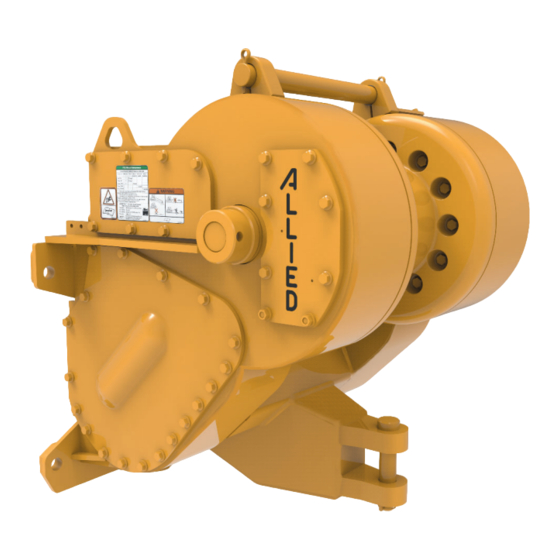
Allied Systems W8L Operating Manual
Towing winch
Hide thumbs
Also See for W8L:
- Service manual (176 pages) ,
- Quick start manual (2 pages) ,
- Operating manual (58 pages)

Related Manuals for Allied Systems W8L


Summary of Contents for Allied Systems W8L
- Page 1 This manual must be with the vehicle on which this winch is installed. Please check the Allied Systems website regularly for updates to this manual. www.alliedsystems.com P/N 599018W 05/10/2017...
- Page 2 Serial Number Winch Model Date Installed Date Delivered Special Equipment or Attachments A Product of Allied Systems Company Sherwood, Oregon 05/10/2017 Printed in U.S.A. U.S.A.
-
Page 3: Foreword
Operating Manual, contact your local winch dealer, in good condition. or contact Allied Systems Company: • Read and understand the SAFETY SUMMARY and OPERATING PROCEDURES contained in this Allied Systems Company Operating Manual. - Page 4 Should there be differences in interpretations to the text, please refer to the English language edition published by Allied Systems Company as the controlling document.
-
Page 5: Table Of Contents
Maintenance ............31 Wire Rope Selection ..........3 Maintenance Points ..........31 Recommended Oil List & Oil Capacity .....4 Maintenance Schedule ........32 W8L Winch Description ..........5 Control Cable Adjustment ........34 Optional Equipment ..........6 Operating Techniques, Power Controls Serial Number Codes ..........7 Tractor & Skidder Identification Codes ....8 Tractor or Skidder Operation ........37... -
Page 6: Contents
® Contents (continued) Operating Techniques, General Appendix A - FREESPOOL How To Move A Disabled Vehicle......45 Description .............51 Working on A Steep Slope ........47 Checks before Operation ........52 Tractor Is Down The Slope .......47 Checks during Operation ........52 Other Equipment Is Down The Slope ....48 Operation Procedures ..........52 FREESPOOL Drag Adjustment ......53 Operational Differences, Optional Equipment... -
Page 7: Safety Summary
Safety Summary Safety Summary General Safety Notices WARNING The following pages contain general safety warnings which supplement specific warnings and cautions T h e “ WA R N I N G ” s y m b o l a p p e a rs appearing elsewhere in this manual. - Page 8 ® NOTE: All possible safety hazards cannot NOTICE be foreseen so as to be included in this manual. Therefore, you must always This signal word alerts to a situation that be alert to potential hazards that could is not related to personal injury but may endanger personnel and/or damage the cause equipment damage.
- Page 9 Safety Summary Obey the following cautions and x Do not work with a damaged or worn wire rope. warnings before using your winch to x Do not use a winch that needs repairs. avoid equipment damage, personal x If the wire rope and ferrule must be removed from injury or death.
- Page 10 ® • Do not leave the vehicle when the winch wire rope • Always inspect wire rope, tail chain and other rigging is under tension. components for wear, damage, broken strands or abuse before use. • Do not permit riders on the vehicle or load. •...
- Page 11 • Replace any parts only with genuine Allied Winch parts. Refer to W8L Parts Manual (P/N 599781W). • Do not attempt to pull loads in excess of the rated capacity of the winch.
- Page 12 ® • This winch is neither intended, designed, nor rated x Infection and gangrene are possible when for any application involved in the lifting or moving hydraulic oil penetrates the skin. See a doctor of personnel. immediately to prevent loss of limb or death. •...
-
Page 13: General
This Operating Manual contains basic information Removable covers on the winch case allow access for repairs and adjustments. necessary for the operation and maintenance of the W8L winch. When PTO is rotating, the hydraulic pump shaft is also rotating. Oil from the hydraulic pump is used to cool How the Winch Operates and lubricate the winch components. -
Page 14: Nameplate
Nameplate Each winch is shipped from the factory with a nameplate as shown in Figure 1. The nameplate is stamped with: • winch model • winch serial number • maximum bare drum line pull • maximum wire rope diameter DO NOT operate the winch with larger diameter wire rope. If the nameplate is missing, DO NOT operate the winch until its capacity is known. -
Page 15: Wire Rope Selection
General Wire Rope Selection WARNING Each winch model can have a variety of wire rope sizes Load loss hazard. installed by the user. The maximum wire rope size is shown on the nameplate. See Figure 2 for approved wire rope A loaded wire rope with fewer than sizes and drum capacities. -
Page 16: Recommended Oil List & Oil Capacity
Recommended Oil List and Oil Capacity The type of oil used in Allied winches affects the line control. Use the following oils in the W8L winch: Recommended Oils* - General Conditions Ambient Temperature Range Manufacturer Oil Type °F °C ExxonMobil... -
Page 17: W8L Winch Description
15. Drawbar Pin Access Cover to Hydraulic System 10. Intermediate Shaft Bearing Retainer 16. Clutch Shaft Retainer Plug to Check Oil Level 11. Drum Shaft Bearing Retainer 17. Brake Shaft Retainer Plug to Drain Oil 12. Drawbar Figure 5 - W8L Winch... -
Page 18: Optional Equipment
Optional Equipment (See also Page 51 for details) • Alternate gear ratio - To allow better line speed control; • Electronic controls - Line control. The W8L winch may be equipped with the following options: NOTE: Not all optional equipment listed is available for each model of tractor. -
Page 19: Serial Number Codes
The nameplate with the serial number code is found on the left front corner of the winch case. A serial number indicates the following information: 1555 Manufactured By A = Allied Systems Company Vehicle Code (No "A" = Hyster Company) See Figure 7 Winch Model... -
Page 20: Tractor & Skidder Identification Codes
Figure 7 - Tractor Identifi cation and Gear Ratio Tractor Make Model and Starting Tractor Serial Number Where Applicable Fiat-Hitachi/ Caterpillar Terex Dresser Komatsu Zoomlion New Holland D68ESS-12 D85E/PX-15 D700C, 16B PS D7F *a, D700A, TD20E/G/H PS, D80A-12 D700D S/N 10301 &... - Page 21 General Figure 7 - Tractor Identifi cation and Gear Ratio Tractor Make Model and Starting Tractor Serial Number Where Applicable Fiat-Hitachi/ Caterpillar Terex Dresser Komatsu Zoomlion New Holland DX255, FD255, D8N *e, D135A D255 D7R PS D85ESS-2 *f ZD220 ...
- Page 22 Figure 7 - Tractor Identifi cation and Gear Ratio Tractor Make Model and Starting Tractor Serial Number Where Applicable Fiat-Hitachi/ Caterpillar Terex Dresser Komatsu Zoomlion New Holland D7G SERIES II 983 Track Loader S/N 38K *a Caterpillar D7F S/N 94N5660 & UP *b Caterpillar D7 DD S/N 91V, 93N, 64V &...
-
Page 23: Operation, Power Controls
Operation, Power Controls Operation, Power Controls Checks Before Operation Operating Procedures • Check that the cable and hook are not worn or The control lever assembly is connected to the winch damaged. Check that the periodic inspection and through a control cable to the control valve spool. This maintenance have been done at the recommended lever is used to select one of the following operations: operating hours. - Page 24 The BRAKE-OFF position is a detent position, and the control lever must be pulled back to the BRAKE-ON (neutral) position. Hydraulic pressure is applied to release the brake. The winch will not rotate easily because of friction in the clutches, the brake and the gear train. Wire rope cannot be pulled from the winch by hand.
-
Page 25: Power Operation
Operation, Power Controls Power Operation BRAKE-ON position is a neutral position. Neither clutch LINE-OUT position applies the LINE-OUT clutch and is applied. The brake is fully applied. releases the brake. The winch will unwind the wire rope at a speed controlled by the PTO speed of the tractor and the weight of the load. - Page 26 Inching is used for a fi ne control of the winch speed. When the power control lever is slowly moved to a position between BRAKE-ON and LINE-IN or between BRAKE-ON and LINE-OUT, inching occurs. The normal adjustment of inching for LINE-IN is different from the adjustment for LINE-OUT.
-
Page 27: Troubleshooting Chart
Operation, Power Controls Troubleshooting Analysis Chart PROBLEM POSSIBLE CAUSE CORRECTION Operation is rough or not regular. Hydraulic oil is too cold. Put the control lever in the BRAKE-OFF position, and run the engine at 1000 rpm to warm the oil to 80°F before operating the winch. - Page 28 PROBLEM POSSIBLE CAUSE CORRECTION Use the BRAKE-OFF position less. Winch has been operated in the Hydraulic oil becomes too hot. When the BRAKE-OFF position is used, BRAKE-OFF position for long the hydraulic oil fl ows continuously periods. through the relief valve. See the Service Manual for additional troubleshooting.
- Page 29 Operation, Power Controls PROBLEM POSSIBLE CAUSE CORRECTION Worn or damaged clutch. See the Service Manual for additional Clutch does not apply troubleshooting, checks and correctly. Control valve or control cable adjustments. needs adjustment. Low oil pressure. Accumulator not charged. Clutch does not apply correctly Check accumulator.
- Page 30 Intentionally Blank...
-
Page 31: Operation, Electronic Controls
Operation, Electronic Controls Operation, Electronic Controls Checks Before Operation Checks During Operation • Check that the cable and hook are not worn or • Check the winch indication light: damaged. - Light steady on after oil warmup means some • Check that the periodic inspection and maintenance problem(s). -
Page 32: Operating Procedures
Operating Procedures NOTE: The fi lter LED illuminates briefl y at startup. This is part of the normal system check. Consult the The electronic control lever is connected to the winch troubleshooting guide (see Figure 13) if the light does through electrical wiring, an electronic control module, a not turn off. - Page 33 Operation, Electronic Controls NON-CURRENT NON-CURRENT CURRENT Figure 11-1 - Control Levers...
- Page 34 Figure 11-2 - Operator Electronic Controls...
-
Page 35: Power Operation
Operation, Electronic Controls Power Operation Note: Black dots represent the positions of the control lever. BRAKE-ON is a neutral position. Neither clutch is applied. LINE-OUT position applies the reverse clutch and The brake is fully applied. releases the brake. The winch will unwind the wire rope at a speed controlled by the PTO rpm of the tractor and the weight of the load. -
Page 36: Inching
As the brake is released, the clutch computer program changes and may be necessary takes control and begins to move the load. for some customer operations. Contact Allied Systems Company if inching needs adjustment. The following paragraphs describe the normal procedures for inching. -
Page 37: Troubleshooting Chart
Operation, Electronic Controls Troubleshooting Chart PROBLEM POSSIBLE CAUSE CORRECTION Operation is rough or irregular. Hydraulic oil is too cold. Put the control lever in the BRAKE-OFF position. Run the engine at 1000 rpm to warm the oil before operating the winch. Low oil level. - Page 38 PROBLEM POSSIBLE CAUSE CORRECTION Brake begins to release before Brake is worn. See the Service Manual for additional clutch is applied. troubleshooting. Winch brake does not apply or Brake is worn. See the Service Manual for additional release correctly. troubleshooting. Low oil pressure.
- Page 39 Operation, Electronic Controls PROBLEM POSSIBLE CAUSE CORRECTION Winch will not freespool (older Inadequate freespool piston Inspect freespool shaft O-rings and models). pressure. replace as necessary. Tighten loose fi ttings. Control lever does not return Defective return spring, worn detent See the Service Manual for additional to BRAKE-ON position when parts, or lubricant evacuation.
- Page 40 PROBLEM POSSIBLE CAUSE CORRECTION Winch will not operate in any Control lever off-center at startup. Return control lever to the BRAKE-ON function. position and attempt function again. Control module not powered. Check fuse & replace if necessary. Control lever DC-DC converter Check converter &...
- Page 41 Operation, Electronic Controls PROBLEM POSSIBLE CAUSE CORRECTION Noisy buzz emanating from Air in relief cartridge. This is not a detrimental condition. Noise winch. may be intermittent. Control lever will not detent in Detent pin, plate, or spring worn or Replace appropriate parts. Note: see BRAKE-OFF.
- Page 42 Intentionally Blank...
-
Page 43: Maintenance
Use the operating Maintenance Points Access Cover for Control Valve Cover for Filter & Strainer Plug to Check Oil Level Fill Plug Plug to Drain Oil Breather Figure 14 - W8L Winch Maintenance Points... -
Page 44: Maintenance Schedule
Maintenance Schedule INTERVAL PROCEDURE OR QUANTITY SPECIFICATION 50 hours or weekly. Check oil level at plug (item 2). Add oil as See Figure 3 – Recommended Oil List. necessary through fi ll plug (item 5). Do not operate tractor when checking the oil level. Check winch control lever (cable controls). - Page 45 Maintenance INTERVAL PROCEDURE OR QUANTITY SPECIFICATION 1000 hours or every 6 Change the hydraulic oil. Drain oil from plug See Figure 3 – Recommended Oil List. months. (item 3). Clean the oil strainer. Through fi ll plug † (item 5), add 20 gallons (75 liters) .
-
Page 46: Control Cable Adjustment
Control Cable Adjustment There are three configurations of operator controls normally used on the W8L winch. Adjustments of the three 2. Power Control Lever confi gurations are described in the following paragraphs. 4. U-Bolt Check the operation of the power control lever to make 5. - Page 47 Maintenance B. See Figure 17. Make sure the positions of the power control lever are the same as the position indicators on the decal. Remove the access cover (Item 1) on the housing to make adjustments. Loosen the jam nut (Item 8) that keeps the tall nut (Item 3) from turning.
- Page 48 C. See Figure 18. Make sure the positions of the power control lever (Item 1) are the same as the position indicators on the decal. Loosen the U-bolt (Item 4) that holds the power control cable (Item 5) in place. Turn the jam nut (Item 3) to adjust the power control cable.
-
Page 49: Operating Techniques, Power Controls
Operating Techniques, Power Controls Operating Techniques, Power Controls Tractor or Skidder Operation Note: Black dots indicate the position of the control levers. Step 1. The tractor or skidder is moved to an area where Step 2. A load (logs) is connected to the wire rope. a load will be connected. - Page 50 Step 3. The operator can move the control lever to the Step 4. If the tractor or skidder must travel through an LINE-IN position. If the load is less than approximately area with bad traction conditions, the operator can move 75% of the maximum line pull, the operator can begin the control lever to the BRAKE-OFF (DETENT) position.
- Page 51 Operating Techniques, Power Controls Step 5. When the vehicle is on fi rm ground, the operator Step 6. When the operator wants to disconnect from the can move the control lever to LINE-IN position to pull the load, the vehicle is stopped and the control lever is moved load toward the vehicle.
- Page 52 Intentionally Blank...
-
Page 53: Operating Techniques, Electronic Controls
Operating Techniques, Electronic Controls Operating Techniques, Electronic Controls Tractor or Skidder Operation LINE-OUT BRAKE-ON Step 1. The tractor or skidder is moved to an area Step 2. A load (logs) is connected to the wire rope. The where a load will be connected. The operator turns on operator moves the control lever to the BRAKE-ON the activation switch, and moves the control lever to the position. - Page 54 BRAKE-OFF LINE-IN Step 3. The operator can move the control lever to the Step 4. If the tractor or skidder must travel through an LINE-IN position. If the load is less than approximately area with bad traction conditions, the operator can move 75% of the maximum line pull, the operator can begin the control lever to the BRAKE-OFF (DETENT) position.
- Page 55 Operating Techniques, Electronic Controls BRAKE-OFF LINE-IN Step 5. When the vehicle is on fi rm ground, the operator Step 6. When the operator wants to disconnect from the can move the control lever to LINE-IN position to pull the load, the vehicle is stopped and the control lever is moved load toward the vehicle.
- Page 56 Intentionally Blank...
-
Page 57: Operating Techniques, General
Operating Techniques, General How to Move a Disabled Vehicle 4. If the vehicle travels faster than the winch winds the wire rope, disengage the transmission until the winch A. A vehicle equipped with a winch can be used to remove wire rope is tightened again. - Page 58 B. A tractor or skidder equipped with a winch can be used 1. Fasten the winch wire rope to the tow bar of the other to pull another vehicle from mud or other areas where it vehicle. The wire rope must be in a direction that is cannot move using only the drive wheels or tracks.
-
Page 59: Working On A Steep Slope
Working on a Steep Slope tractor, a structure or a tree that has enough strength to hold the tractor on the slope. WARNING A. Moving down the slope: Death or equipment loss hazard. 1. Set the throttle on the tractor for the required engine speed. -
Page 60: Other Equipment Is Down The Slope
Operating Techniques, General B. Moving up the slope: Other Equipment is Down the Slope (See Figure 21). 1. Set the throttle on the tractor for the required engine In this operation, the tractor and winch are on stable speed. ground and other equipment is working on a steep slope. - Page 61 A. Lowering the equipment on the slope: B. Raising the equipment on the slope: 1. Set the throttle on the tractor for the required engine 1. Set the throttle on the tractor for the required engine speed. Operator experience is required for this speed.
-
Page 62: Operational Differences, Optional Equipment
Operational Differences, Optional Equipment Operational Differences, Optional Equipment Fairlead Drawbar A fairlead consists of a set of top and bottom horizontal Do not use the drawbar as an anchor point for a two-part rollers and side rollers that the wire rope is fed through. line from the winch. -
Page 63: Appendix A - Freespool
Appendix A - FREESPOOL FREESPOOL Description Some W8L power controlled winches of very early is no load on the wire rope. When the control lever is in production were equipped with an optional FREESPOOL the FREESPOOL position, the sliding sleeve disengages function. -
Page 64: Checks Before Operation
Checks Before Operation FREESPOOL control lever has two positions: NORMAL OPERATION and FREESPOOL. • Check that the cable and hook are not worn or damaged. Check that the periodic inspection and maintenance have been done at the recommended operating hours. (See Figure 15, Maintenance Schedule.) •... -
Page 65: Freespool Drag Adjustment
The FREESPOOL operation permits the wire rope to be pulled from the On W8L winches with S/N 2033 and above, an adjusting winch drum by hand. screw is located in the center of the bearing retainer for the intermediate shaft;... - Page 66 CAUTION Bearing overload hazard. Setting the preload on the intermediate shaft too tight will cause bearing overload. Setting the preload too loose will allow shaft to not be parallel. Use caution when adjusting. Start with the preload too loose, and gradually increase the preload until the correct resistance to rotation is achieved.
-
Page 67: Control Cable Adjustment
Appendix A - FREESPOOL Control Cable Adjustment A. See Figure 26. Check that the positions of the 1. Freespool Control Lever FREESPOOL lever (Item 1) are the same as the position 2. Power Control Lever indicators on the control housing. Loosen the U-Bolt 3. - Page 68 B. See Figure 27. Check that the positions of the FREESPOOL lever are the same as the position indicators on the decal. Remove the access cover on the housing. Loosen the nut that keeps the tall nut from turning. Remove the cotter pin and link pin from the clevis.
- Page 69 Appendix A - FREESPOOL C. See Figure 28. Check that the positions of the FREESPOOL lever (Item 1) are the same as the position indicators on the decal. Loosen the U-bolt that holds the FREESPOOL cable (Item 9) in place. Turn the jam nut to adjust the FREESPOOL cable.
-
Page 70: Tractor Or Skidder Operating Techniques
Tractor or Skidder Operating Techniques Note: Black dots indicate the position of the control levers. READ OPERATING READ OPERATING INSTRUCTIONS INSTRUCTIONS 271731W 271731W Step 1. The tractor or skidder is moved to an area where Step 2. A load (logs) is connected to the wire rope. a load will be connected. - Page 71 Appendix A - FREESPOOL READ OPERATING READ OPERATING INSTRUCTIONS INSTRUCTIONS 271731W 271731W Step 3. The operator can move the control lever to the Step 4. If the tractor or skidder must travel through an LINE-IN position. If the load is less than approximately area with bad traction conditions, the operator can move 75% of the maximum line pull, the operator can begin the control lever to the BRAKE-OFF (DETENT) position.
- Page 72 READ OPERATING READ OPERATING INSTRUCTIONS INSTRUCTIONS 271731W 271731W READ OPERATING INSTRUCTIONS 271731W Step 5. When the vehicle is on fi rm ground, the operator Step 6. When the operator wants to disconnect from the can move the control lever to LINE-IN position to pull the load, the vehicle is stopped and the control lever is moved load toward the vehicle.
- Page 74 To find a dealer in your area, Call: 503.625.2560, Fax: 503.625.7269, or 599018W 05/10/2017 Printed in U.S.A. Email: marketing@alliedsystems.com, or Visit our website: www.alliedsystems.com...
Need help?
Do you have a question about the W8L and is the answer not in the manual?
Questions and answers