Advertisement
Quick Links
Multi Format Switcher System
XVS-G1 System
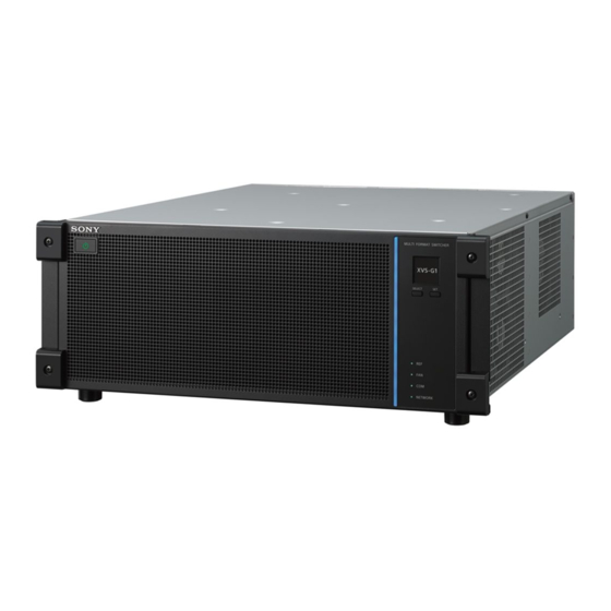
XVS-G1
XKS-G1110
XKS-G1600
XZS-G1500
XZS-G1610
XZS-G1800
ICP-X7000
MKS-X7075
MKS-X7020
MKS-X7021
MKS-X7031TB MKS-X7032
MKS-X7041
MKS-X7042
ICP-X1116
ICP-X1124
User's Guide
Software Version 1.2 and Later
1st Edition (Revised 2)
XKS-G1700
XZS-G1620
MKS-X7017
MKS-X7023
MKS-X7033
ICP-X1216
[English]
XZS-G1750
XZS-G1770
MKS-X7018
MKS-X7019
MKS-X7024
MKS-X7026
MKS-X7035
MKS-X7040
ICP-X1224
Advertisement
Chapters

Related Manuals for Sony XVS-G1


Summary of Contents for Sony XVS-G1
- Page 1 Multi Format Switcher System XVS-G1 System XVS-G1 XKS-G1110 XKS-G1600 XKS-G1700 XZS-G1500 XZS-G1610 XZS-G1620 XZS-G1750 XZS-G1770 XZS-G1800 ICP-X7000 MKS-X7075 MKS-X7017 MKS-X7018 MKS-X7019 MKS-X7020 MKS-X7021 MKS-X7023 MKS-X7024 MKS-X7026 MKS-X7031TB MKS-X7032 MKS-X7033 MKS-X7035 MKS-X7040 MKS-X7041 MKS-X7042 ICP-X1116 ICP-X1124 ICP-X1216 ICP-X1224 User’s Guide [English] Software Version 1.2 and Later...
- Page 2 NOTICE TO USERS © 2021, 2022 Sony Corporation. All rights reserved. This manual or the software described herein, in whole or in part, may not be reproduced, translated or reduced to any machine readable form without prior written approval from Sony Corporation.
-
Page 3: Functions Supported In Version 1.2
Functions relating to operability Functions Supported in Version 1.2 Classification Functions Menu number See page The functions newly supported in XVS-G1 System supported Ver. 1.2 are as follows. Menu Key settings 11101.11 to 13 page 74 default recall 11101.21 to 23 Notes 11101.31... -
Page 4: Table Of Contents
Utility Control Block........55 Operation Mode of a Button Row ....83 Power Supply and Connectors ....57 Bus Types and Assignments......84 XVS-G1 Multi Format Switcher ....57 Selecting a Bus (AUX Bus Control ICP-X7000 Control Panel ......60 Block) ..........86 ICP-X1000 Series Control Panel....61 Operation Mode of a Button Row ....86... - Page 5 Selecting Signals ........87 Basic Independent Key Transition Operations ........108 Assigning Signals ........87 Setting the Independent Key Transition Cross-Point Button Numbers ......87 Type ..........108 Cross-Point Button Display......89 Setting the Independent Key Transition Cross-Point Hold .........89 Rate ..........110 Selecting a Key Fill Signal/Key Source Executing an Independent Key Signal ..........90 Transition .........111...
- Page 6 Processed Keys ........133 Wipe Snapshot Operations (Menu) ...161 DME Effects for Keys.......133 Selecting a DME Channel (Menu) ....134 Selecting a DME Channel (Key Control Chapter 8 DME Wipes Block)..........134 Other Settings ......... 136 Overview ..........163 Blink ............136 Setting a DME Wipe ........ 166 Video Process ..........136 Setting a DME Wipe Pattern .....166 Show Key ..........136...
- Page 7 Still Image Operations ......183 Setting a Crop..........206 Creating a Still Image (Freeze) ....183 Setting a Wipe Crop ........207 Recalling a Still Image ......183 Video Modifier Effects ......208 Video Operations ........184 Setting Defocus .........208 Creating Video (Record) ......184 Setting Sepia..........208 Recalling Video.........184 Setting Mono ..........209...
- Page 8 Control of GPI Devices ......229 Executing a Copy/Swap ......251 GPI Timeline ..........229 DME Override .......... 252 Control of Routers ........230 DME Channel Status Display ....252 Destination Input List Display ....230 Selecting a Level ........230 Switching the Destination Input ....230 Chapter 15 Effect Timelines Router Operations (AUX Bus Control Block)..........231...
- Page 9 Executing a Shotbox (Utility/Shotbox Control Chapter 16 Snapshots Block)..........300 Executing a Shotbox (Utility Control Overview ..........280 Block)..........301 Attributes ...........280 Executing a Shotbox (Cross-Point Control Bus Override ..........281 Block)..........301 Snapshot Operations (Flexi Pad Executing a Shotbox (Numeric Keypad Control Block)........281 Control Block) .........301 Recalling a Snapshot .........282 Executing a Shotbox (Menu).....302...
- Page 10 Editing a Macro Register......323 Chapter 20 Content Management Macro Attachments......... 324 Overview ...........324 Overview ..........347 Setting a Macro Attachment......325 Content Operations......... 348 Displaying a Macro Attachment List ..327 Displaying Content........348 Executing a Macro Assigned in a Macro Copying Content........351 Attachment........328 Moving Content.........352 Macro Timelines ........
- Page 11 Setting a Frame Delay .......369 Setting a User Region........387 Setting a Frame Synchronizer ....369 Setting a Multi Viewer ......388 Setting a Format Converter .......369 Assigning Signals ........388 Setting a Color Corrector ......371 Displaying a Signal Name......389 Setting an HDR Converter ......371 Displaying an Audio Level Meter .....389 Setting the Output Signal .......
- Page 12 Setting Dual M/E........396 Adjusting the Control Panel Buttons/ Display..........418 Setting Regions Selected Simultaneously......... 397 Setting Sleep Mode ........418 Assigning Control Panel Buttons..397 Adjusting the Button/Display Brightness ........418 Assigning Buttons (ICP-X7000) ....397 Setting the Lit State of Buttons When Assigning Buttons (ICP-X1000 series) ..399 Off ............418 Setting Transition Rate Display Mode...
- Page 13 Setting the Date and Time ...... 449 Chapter 27 Link Setup Setting the Time Zone .......449 Setting the Date/Time........449 Setting a Cross-Point Button Link..435 Firmware Version Management and Setting a Bus Link ........435 Installation ........450 Setting a link table........435 Displaying Package Status ......450 Setting an M/E Link .........
-
Page 14: Introduction
For details about system signal formats, see “Setting the System configuration devices Signal Format and Frequency” (page 365). The principal components of the XVS-G1 system are as follows. For details about input/output signal formats, see “Setting a Format Converter” (page 369) and “Setting a... -
Page 15: Chapter 2 Names And Functions Of Parts
Names and Functions of Parts Chapter Control Panel The XVS-G1 Multi Format Switcher System is Note comprised by a single switcher and up to two control Some button operations and menu settings may be panels. disabled depending on the configuration of installed The ICP-X7000 Integrated Control Panel or ICP-X1000 options and connected control panels. -
Page 16: Control Panel Configuration (Icp-X7000)
Control Panel Configuration (ICP-X7000) The ICP-X7000 Integrated Control Panel is a control Control block Module panel that comprises multiple modules. Flexi Pad control block MKS-X7024 The control blocks and supported modules of the control Key control block MKS-X7035 panel are described below. Key fader control block MKS-X7032 Control block... - Page 17 Configuration example using a simple-type transition control block a AUX bus control block (see page 40) j Key control block (see page 29) A cross-point module connected in an AUX bank row is Up to four key control block modules can be connected. used as an AUX bus control block.
-
Page 18: Cross-Point Control Block
Cross-Point Control Block The cross-point control block is used to select the signals You can set the mode to key/AUX bus delegation mode to be used in the switcher bank. or free assign mode in the Home > Setup > Panel > Xpt The button rows on the cross-point control block are set Module >... - Page 19 Cross-point pad operation Name Description 4th row • Selects the background B bus signal when in key/AUX bus delegation mode or key bus Current page mode. name display • Selects the bus signal assigned by the button HOME button delegation buttons in the cross-point pad when in free assign mode.
- Page 20 Function name Button Description Function name Button Description name name Others: Displays the currently Row-n Func: Displays the bus/ M/E Status M/E1 to set switcher bank. Assign Status function name assigned M/E5 In multi program 2 to the 1st row to 4th mode, the main and sub row.
- Page 21 Function name Button Description Function name Button Description name name Row-n Func: ROWn Assigns cross-point Others: MACRO: Displays the currently Table 1 to Table 14 TBL: 1 to assign tables 1 to 14 to Macro Register recalled macro register TBL: 14 the 1st row to 4th row.
-
Page 22: Transition Control Block
a) Disabled in key/AUX bus delegation mode. Function name Button Description b) Disabled in key bus mode. name c) 3rd row and 4th row are disabled in key bus mode. d) Disabled for SL keys. Others: XPTPAD Copies cross-point pad e) 1st row is disabled in key/AUX bus delegation mode. - Page 23 a Transition execution section For details about assigning buttons, see “Assigning Control Panel Buttons” (page 397). Next transition selection buttons Transition indicator Function Button Description name name Background BKGD Switches the background for a Fader lever next transition. Key 1 to KEY1 to Inserts or removes the selected Key 8...
- Page 24 d Independent key transition execution section Function Button Description name name Reverse The wipe proceeds in the Display opposite direction of normal (reverse). Transition preview buttons Function Button Description name name Transition TRANS Switches the transition preview Preview mode. You can check a transition using preview output.
-
Page 25: Transition Control Block (Simple Type)
Transition Control Block (Simple Type) The simple-type transition control block is used to Function Button Description execute background transitions. name name DME Wipe DME Selects DME wipe. For details, see “Chapter 5 Transitions” (page 93). WIPE FM 1&2 FM1&2 Selects clip transition. Clip to FM CLIP to 15&16 Clip... -
Page 26: Independent Key Transition Control Block
c Fader lever/transition indicator Pattern limit setting buttons The following functions can be assigned to the four buttons at the top only. Function Button Description name name Fader lever Limit Set LIMIT SET Sets the pattern limit. Pattern PTN LIMIT Enables the pattern limit. Lock button Limit Main/sub switching buttons (multi program 2... -
Page 27: Flexi Pad Control Block
Function name Button Description Notes name • The [KEYx ON] button (x = 1 to 8) and the [AUTO Other Banks: KEY1 ON Inserts or removes a key TRANS] button for the same key are assigned as a set. M/E-x Key 1 to KEY8 instantaneously. - Page 28 Numeric keypad mode Function Button Description Pressing the [BANK SEL] button, [PTN NO.] button, or name name [PAUSE] button switches the memory recall section to Macro MCRO Switches to macro operation numeric keypad mode, where you can enter bank mode. numbers, wipe pattern numbers, and pause event times.
-
Page 29: Key Control Block
Key Control Block The key control block is used to adjust and modify keys. For details, see “Chapter 6 Keys” (page 115). a Delegation buttons While the [TRANS] button/[SUB TRANS] button is selected, you can assign a DME channel to use in a DME Button Description wipe. - Page 30 Resizer operation buttons Performs two-dimensional transforms (shrink/magnify, Setting button display area: PAGE 1/3 move, rotate) on keys using a resizer. When a button is selected, the parameters appear on the display and you can set the parameters using the adjustment knobs. •...
-
Page 31: Key Fader Control Block
f Display Button Description Displays the parameter names and setting values. name AUTO Switches the delegation of the key control g Adjustment knobs DELEG block automatically in sync with the following Adjusts the parameters for the item selected by the setting control block buttons. - Page 32 b Independent key transition execution section d Key snapshot operation buttons Button name Description K-SS 1 to Selects key snapshot register 1 to 4. K-SS 4 K-SS Switches to key snapshot operation mode. K-SS STORE Saves a key snapshot in the selected register when a [K-SS 1] to [K-SS 4] button is pressed while pressing the [K-SS KEY ON buttons...
-
Page 33: Device Control Block
Device Control Block The device control block is used for three-dimensional transforms using a DME, two-dimensional transforms using a resizer, executing effect timelines, controlling devices/frame memory/clip players, entering menu parameters, and other functions. a Mode selection buttons / channel selection buttons Function Button name Description... - Page 34 Channel selection buttons Function Button Description name name Function Button Description Shift SHIFT Used in combination with the name name [CTR], [CLR WORK BUFR], and Channel 1 to CH1 to CH1 to CH4: [BDR/CROP] buttons. Channel 12 CH12 Selects the target DME Clear Work •...
- Page 35 Function Button Description Function Button Description name name name name Center • When the [CTR] button is Location LOC SIZE • Moves an image using the Size pressed once: trackball. Adjusts the two-dimensional • Scales an image (shrink/ transform parameters to the magnify) using the Z-ring.
- Page 36 For details about clip player operations, see “Playing Function Button Description Video” (page 192). name name Center • When the [CTR] button is c Trackball pressed once: This adjusts the parameters of items selected in resizer Adjusts the three-dimensional operation mode, three-dimensional transform operation transform parameters to the mode, and menu parameter operation mode.
-
Page 37: Numeric Keypad Control Block
Numeric Keypad Control Block The numeric keypad control block is used for selecting shotboxes, for recalling and creating macros, for entering regions, recalling and saving effect timelines/snapshots/ the transition rate, and for other tasks. a Mode selection buttons Notes Button Description •... - Page 38 Function name Button name Description Button name Description User: USER1 to User regions +/– • Inverts the + (plus) and User 1 to User 8 USER8 EFF DISS – (minus) signs. • In effect timeline operation mode – Select all regions and snapshot operation mode, configured use to add the effect dissolve...
-
Page 39: Utility/Shotbox Control Block
Utility/Shotbox Control Block The utility/shotbox control block is used to execute functions assigned to memory recall buttons, edit and execute effect timelines, edit macros, display the transition rate, and other tasks. a Mode selection buttons / operation buttons / bank Effect timeline operation buttons selection buttons (assignable buttons) Function name... -
Page 40: Aux Bus Control Block
b Memory recall section (memory recall buttons) Bank selection buttons This section displays the functions assigned to the buttons Function name Button name Description for the selected operation mode. Bank 1 to Bank BANK1 to Switches the memory BANK20 recall section to Note function recall mode of the selected bank. - Page 41 b Display Name Description In AUX bus operation mode, the following information is 3rd row • When second delegation mode is enabled, displayed. selects the signal for the bus assigned by • Settings of buttons on the 1st row to 4th row (bus name the 1st row delegation buttons.
- Page 42 For details about the method of operation, see “Cross- Function name Button Description point pad operation” (page 19). name Others: Displays the signal name/ Assignable functions Selected Src source name selected by Status the bus/destination on the Function name Button Description 1st row or 2nd row name...
- Page 43 Function name Button Description name Others: AUX MIX In second delegation 2nd Aux Mix mode, executes an AUX mix on the 4th row. Others: Selects the signal on the key side in the 3rd row and 4th row. In second delegation mode, selects the signal on the key side in the 3rd row.
-
Page 44: Control Panel Configuration (Icp-X1000 Series)
Control Panel Configuration (ICP-X1000 Series) The ICP-X1000 series Compact Control Panel supports the following four types of control panel according to the number of M/E banks and cross-point buttons. Control panel Number of M/E Number of cross- banks point buttons ICP-X1224 ICP-X1216 ICP-X1124... -
Page 45: Cross-Point Control Block
Cross-Point Control Block The cross-point control block is used to select the signals You can set the mode to key bus mode or free assign to be used in the switcher bank. mode in the Home > Setup > Panel > Xpt Module > The button rows on the cross-point control block are set Operation Mode menu (19104.31). - Page 46 d Function button section (assignable buttons) Name Description You can assign functions, such as settings and operations, 3rd row • Selects the background A bus signal when of the cross-point button rows in the Home > Setup > in key/AUX bus delegation mode or key Panel >...
- Page 47 Function name Button Description Function name Button Description name name Others: PRE MCRO Sets macro attachment Others: INHBT Releases inhibit mode Pre Macro in pre-macro mode. Xpt Inhibit All Clear ALLCLR for all cross-point buttons. Others: POST Sets macro attachment Post Macro MCRO in post-macro mode.
-
Page 48: Transition Control Block
Transition Control Block The transition control block is used to execute transitions. For details, see “Chapter 5 Transitions” (page 93). It supports common transitions and independent key transitions. Transition indicator Fader lever AUTO TRANS button CUT button a Transition execution section Next transition selection buttons Name Description... - Page 49 Transition type selection buttons Main/sub switching buttons (multi program 2 mode) Function Button name Description name Function Button name Description name Selects mix. Main MAIN Switches operation to the Selects NAM (non- function on the main side additive mix). in multi program 2 mode. Super Mix SUPER MIX Selects super mix.
-
Page 50: Flexi Pad Control Block
Flexi Pad Control Block The Flexi Pad control block is used for recalling and Function Button name Description saving snapshots, wipe snapshots, DME wipe snapshots, name and key snapshots, for recalling and creating macros, for Wipe WIPE Switches to wipe recalling shotboxes, for entering the transition rate, and snapshot operation mode. -
Page 51: Device Control Block
b Memory recall section (memory recall buttons) Notes This section displays the functions assigned to the buttons • The [UNDO] button and [DEL] button cannot be used for the selected operation mode. in shotbox operation mode. The top right button is used to display the selected pattern •... - Page 52 Mode selection buttons Function Button name Description name Function Button name Description Clip Player 1 CLIP1 to Selects the target clip name to Clip Player CLIP4 player output channel in Menu MENU • Switches to menu device/frame memory/clip parameter operation player operation mode.
- Page 53 Function Button name Description Function Button name Description name name Clear Work CLR WORK • When the [CLR WORK M/E Default M/E DEF When the [M/E DEF Buffer BUFR Recall RCALL RCALL] button is pressed BUFR] button is twice: pressed once: Returns the switcher bank Returns the two- to the initial settings.
- Page 54 Function Button name Description Function Button name Description name name Aspect/ ASP PERS • When the [ASP PERS] Restricts the parameters Perspective targeted by the operation. button is pressed in When the [X] button is lit: source space: Operations on Adjusts the aspect ratio parameters on the X-axis of an image using the...
-
Page 55: Utility Control Block
For details about clip player operations, see “Playing Function Button name Description Video” (page 192). name Fine FINE Switches to fine mode, c Trackball enabling fine adjustment This adjusts the parameters of items selected in resizer control of setting values using the trackball and Z- operation mode, three-dimensional transform operation ring. - Page 56 Numeric keypad mode Function Button name Description Pressing the [BANK SEL] button switches the memory name recall section to numeric keypad mode, where you can Menu MENU Switches to menu enter bank numbers. parameter operation The currently set numeric value or the value entered in mode.
-
Page 57: Power Supply And Connectors
The following six items are displayed in sequence each You can switch the display items using the [SELECT] time the [SELECT] button is pressed. button. • Model name of the switcher (XVS-G1) • Host name of the switcher For details, see “Display items and operations” • IP/Mac Address: (page 57). - Page 58 For details, see “Resetting the password of the administrator user account” (page 67). Rear view a OUTPUT 1 to 12 connectors (BNC type) g LAN 2 connector (RJ-45, 1000BASE-T compliant) Program outputs, preview outputs, and AUX outputs can LAN connector for standard interface 2. be assigned and output as serial video signals.
- Page 59 RS-422 compliant) Can be used when an XKS-G1700 Legacy Interface Board (option) is installed. Connect to a device that supports VTR (Sony 9-pin VTR protocol), disk recorder (Video Disk Communications Protocol, Odetics protocol), or P-Bus (Peripheral Bus II protocol) protocols.
-
Page 60: Icp-X7000 Control Panel
For details about PoE+ (Power over Ethernet Plus) Connect to the supplied AC adaptor. compatible Ethernet switches that can be used, consult your Sony representative. b LAN connector (RJ-45, PoE+, 1000BASE-T compliant) Connect to the switcher system network via an Ethernet switch. -
Page 61: Icp-X1000 Series Control Panel
Side view ICP-X7000 Integrated Control Panel MKS-X7075 Extension Adaptor a U (signal ground) terminal Connect to a ground wire. ICP-X1000 Series Control Panel Rear view The following illustration shows the ICP-X1224. a DC IN A and B connectors d LAN A2 connector (RJ-45, 1000BASE-T Connect to the supplied AC adaptor. -
Page 62: Input Connectors And Output Connectors
Input Connectors and Output Connectors Input/output connector numbers INPUT OUTPUT Row 4 (INPUT 37 to 44) Row 4 (OUTPUT 19 to 24) Row 3 (INPUT 25 to 36) Row 3 (OUTPUT 13 to 18) Row 2 (INPUT 13 to 24) Row 2 (OUTPUT 7 to 12) Row 1 (INPUT 1 to 12) Row 1 (OUTPUT 1 to 6) -
Page 63: Menu
Menu The menu is used configure data management, setup, and For details about menu operations, see “Chapter 3 Menu other settings related to the switcher and control panel. It Operation” (page 66). can also be used to configure transitions, keys, and image creation settings using menu operations. - Page 64 Press the overflow button to display a pull-down list to select the following items. System Configuration Displays the System Configuration menu. User’s Guide Displays the XVS-G1 User’s Guide. End-User License Agreement Displays the software license information (end user license agreement). System Shutdown Shuts down the system.
-
Page 65: Pop-Up Window
Pop-up Window Depending on the menu button, a pop-up window may be For details, see “Entering a difference from a current displayed in the menu display area when the button is value” (page 77). pressed. Setting / selection window Numeric Keypad Window Displays operation buttons and input fields used to set Displays a numeric keypad for entering numeric values. -
Page 66: Chapter 3 Menu Operation
Overview A root certificate must be installed on the computer in order to use the menu. The XVS-G1 menu is a web-based application. The menu can be operated using the touch panel of a Access the certificate download page. computer (tablet or PC) connected to the switcher system Enter the URL of the certificate download page in a network. -
Page 67: Signing In / Signing Out
Note Signing In / Signing Out A security warning message may appear when displaying the menu screen, but continue the operation. When signing in for the first time using an administrator account Signing out from the web menu By default, “admin” is the only administrator user account registered. -
Page 68: Displaying The User's Guide
Displaying the User’s Displaying License Guide Information You can display the User’s Guide in English or Japanese. Press the overflow button in the header area and select Press the overflow button in the header area and select [End-User License Agreement] from the pull-down list. [User’s Guide] from the pull-down list. -
Page 69: Shutting Down / Rebooting
Shutting Down / Basic Menu Operation Rebooting Menu Selection Shutting Down the System Menu hierarchy and menu number Press the overflow button in the header area and select The menu hierarchy has five levels, with each menu [System Shutdown] from the pull-down list. having a unique menu number. -
Page 70: Setting Menu Items
Level 2 / level 3: Note Level 2 and level 3 menus are displayed in tree format You can also display the Top Menu List menu by on the left side of the menu selection area. selecting [Shortcut] in level 2 of the menu selection area. You can scroll up/down using a swipe operation or using the scrollbar slider. -
Page 71: Selecting And Setting List Items
Tabs Button Description Shortcut button Jumps to the specified menu. On/off switch Turns a function on/off (enable/disable). Radio button Turns a function on/off (enable/disable). Button display status The button display indicates the following according to the status. When the menu display area or a pop-up window Button Status comprises several pages, each page is displayed on a tab. -
Page 72: Setting Parameters
Selecting using a checkbox Changes to the setting of one of the check marked items will apply the same change in setting to the other target To select an item, place a check mark in the checkbox. items. To select multiple items, place a check mark for the target Changes to the setting of a parameter in the analog items for operation. - Page 73 Example: Note Parameters on one page only You can display the guide window by pressing the guide display button. Parameter Adjustment Width Width Entering parameters by touch operation Position Position Density Density You can enter parameters in the parameter adjustment area.
-
Page 74: Initializing Settings (Default Recall)
Returning parameters to the initial Initializing Settings (Default Recall) settings Press the default recall button. You can return a menu to the initial status saved data The parameters return to the initial status saved data setting value if a default recall button is displayed. setting values. -
Page 75: Switching Taskbars
• Home > P/P > Keyx menus [Snapshot] taskbar • Home > P/P Sub > Keyx menus Displays operation buttons for recalling/saving snapshot (M/E-x = M/E-1 to M/E-5, Keyx = Key1 to Key8) registers. When default recall is executed, all the menus below the level 3 menu return to their initial settings. -
Page 76: Registering Menus As Favorites
Registering Menus as Linking a Control Panel Favorites with the Menu You can register frequently used menus or other menus as You can set a menu to operate by linking it with an “favorites.” operation from a control panel. A favorite menu can be recalled by pressing a shortcut Multiple web menu sessions can be connected button displayed in the [Favorites] taskbar. -
Page 77: Entering And Displaying Text/Numbers
Example: Entering and Displaying To set 3 minutes, 7 seconds, and 15 frames, enter “30715”. Text/Numbers Frame number input mode When [TC] in the numeric keypad window is turned off, frame number input mode is selected. Press a numeric keypad input button to display the Enter a value in “fff”... -
Page 78: Selecting And Displaying Regions
Device 4 > Device 5 > Device 6 > Device 7 > Device 8 > Selecting and Displaying Device 9 > Device 10 > Device 11 > Device 12 > P-Bus > GPI > Macro > Router Regions Selecting a Region The term “region”... - Page 79 Region display section The region display section shows the region selection status. • Selected region: White text • Deselected region: Gray text • Reference region: Highlighted display...
-
Page 80: Chapter 4 Selecting Signals
Selecting Signals Chapter Overview You can select a signal using the cross-point button rows in the cross-point control block or AUX bus control block (AUX bus operation mode) of each switcher bank. ICP-X7000 cross-point control block The number of buttons in a button row varies depending Note on the modules used. - Page 81 ICP-X1000 series cross-point control block The number of buttons in a button row varies depending Note on the control panel used. When the button row operation mode is key bus mode or • ICP-X1224, ICP-X1124: 24 buttons free assign mode, the 1st row becomes a cross-point •...
- Page 82 ICP-X7000 AUX bus control block (AUX bus operation mode) The number of buttons in a button row varies depending The illustration below shows a 36-button AUX bus on the modules used. control block (AUX bus operation mode). • MKS-X7017: 36 buttons •...
-
Page 83: Selecting A Bus (Cross-Point Control Block)
For example, to load the image created on M/E-1 as Selecting a Bus background B on M/E-2, press the M/E-1 re-entry button in the cross-point button row for background B bus on (Cross-Point Control M/E-2. Block) Notes • M/E-1 to M/E-3 and P/P re-entry signals are assigned to the cross-point buttons by default. -
Page 84: Bus Types And Assignments
Assignment operation Bus Types and Assignments Utility 1 bus • ICP-X7000: Press Utility 2 bus delegation buttons [UTL1] You can select buses using the delegation buttons for and [UTL2], turning them assignment to cross-point button rows. The assignable buses and assignment operation are as •... - Page 85 Utility bus mode Assignment operation The following buses can be assigned to the 1st row to 4th Frame memory source 1 bus • In free assign mode, press Frame memory source 2 bus row while the [UTIL] button assigned to the cross-point delegation buttons [FMS1] and [FMS2], turning them pad/function button section of the cross-point control...
-
Page 86: Selecting A Bus (Aux Bus Control Block)
Bus Types and Assignments Selecting a Bus (AUX You can select buses using the delegation buttons for Bus Control Block) assignment to the 3rd row/4th row cross-point button rows. The assignable buses and assignment operation are as The cross-point button rows in an AUX bus control block follows. -
Page 87: Selecting Signals
Assignment operation Selecting Signals DME1 key bus to Press the [DME1K] to [DME4K] DME4 key bus buttons in the 1st row/2nd row, turning them on. a) Selects the utility 2 bus on the sub side when in multi program 2 mode. Assigning Signals Signals input to the input connectors and signals generated within the switcher can be selected using the... - Page 88 ICP-X1000 series 24-button cross-point control Notes block • The operation mode of the [SHIFT] button is the operation mode set by the cross-point assign table of the switcher bank, regardless of the buses assigned to the 1 to 23 (1st button number: unshifted state) 24 to 46 (2nd button number: shifted state) cross-point button rows.
-
Page 89: Cross-Point Button Display
When second delegation mode is disabled Cross-Point Button Display In a 36-button row, the button numbers are as follows. Button Button number Button number Source name of signals when the [SHIFT] when the [SHIFT] button is off button is on You can attach a name (source name) to the signal 1st row and 3rd 1 to 35... -
Page 90: Selecting A Key Fill Signal/Key Source Signal
You can set cross-point hold for each cross-point button Selecting a Key Fill Signal/Key row. Source Signal To set cross-point hold, press the [XPT HOLD] button, turning it on, for the 1st row to 4th row assigned to the cross-point pad/function button section. You can select a key fill signal and key source signal using the following methods. -
Page 91: Selecting A Video Signal/Key Signal
For details, see “Setting a key fill/key source” When a cross-point button is pressed, the signal for the (page 124) and “Setting a key fill/key source” front side of the image is selected. When a cross-point (page 125). button is pressed while pressing a DME video bus/DME key bus delegation button in a delegation button row, the signal for the back side of the image is selected. -
Page 92: Preventing Operation Of Cross-Point Buttons
Preventing Operation of a Cross- Preventing Operation of Point Button Row (Protect Function) Cross-point Buttons You can temporarily prevent button operations for each cross-point button row on the cross-point control block. To enable/disable the protect function, use the following Preventing Operation of Cross- buttons. -
Page 93: Chapter 5 Transitions
Transitions Chapter Changing the background Overview To switch the background in a transition, select a background for a next transition. Select a background image using background A bus and Switching from the current output image to a new image background B bus. When set to flip-flop mode, background A is the existing is referred to as a transition. -
Page 94: Basic Operation For Transitions
Transition type Basic Operation for You can set the way in which the transition occurs. You can select the following transition types. Transitions Transition type Description The new image progressively The basic transition operation flow is as follows. fades in over the current image. The sum of the two image outputs is maintained constant, and the Select a background image using the background A... -
Page 95: Next Transitions
For details about transition preview, see “Transition Next Transitions Preview” (page 107). When a wipe or DME wipe is selected as the transition type, you can set the transition execution You can select the switch target of a transition. range (pattern limit). Next transitions are configured using the transition For details about pattern limits, see “Pattern Limit”... -
Page 96: Key Priority
For details about settings, see “Enabling double-press Key Priority for the [BKGD] button in the transition control block” (page 413). To change the key overlay sequence When multiple keys are inserted, you can set the overlay Press the [KEY PRIOR] button. sequence of the keys. -
Page 97: Setting Key Priority
When setting the key priority for after the Setting Key Priority transition Press the [Edit] button for [Next Key Priority]. The [Next Key Priority] window appears. Setting the key priority (transition control block) Set the buttons for the keys to set to priority 1 to 8 to You can set the key priority using the transition control the on state in [Priority 1] to [Priority 8]. -
Page 98: Transition Type
For details, see “Setting Super Mix” (page 99). Transition Type When preset color mix is selected Set the color matte to insert during the transition. For details, see “Setting a Preset Color Mix” You can set the way in which the transition occurs. (page 99). -
Page 99: Setting Super Mix
When a wipe is selected One-time mode: Set the wipe pattern. Return to the previous transition type when the preset color mix transition is completed. For details, see “Setting a Wipe” (page 149). Non-drop key: If a key is inserted in the current image, it is removed When a DME wipe is selected by the color matte during the transition, and the key Set the DME wipe pattern. -
Page 100: Transition Rate
Setting the transition rate (Flexi Pad Transition Rate control block) You can set the transition rate using the Flexi Pad control block of the target switcher bank. You can set the time taken from the beginning of a transition to its completion. Press the [TRANS RATE] button. -
Page 101: Executing A Transition
In frame number input mode, enter three digits. In Executing a Transition timecode input mode, enter four digits. To delete the entered value Press the [CLR] button. Transitions are executed using the transition control block or simple-type transition control block. Note You can also execute auto transitions using the menu. -
Page 102: Auto Transitions
partly completed, or completing a transition started with the fader lever as an auto transition. ICP-X7000 transition control block (simple type) Transition indicator You can check the transition execution status using the transition indicator on the transition control block/ transition control block (simple type). The transition indicator displays the transition execution status by which LEDs are lit and which are not, both for manual transitions and auto transitions. -
Page 103: Manual Transitions (Fader Lever)
Press the [AUTO TRANS] button. • If the fader lever is moved in the direction away from the lit/flashing LEDs, a 100% transition is executed over the remaining part of the fader lever travel and the LEDs turn off. Manual Transitions (Fader Lever) •... - Page 104 Bus fixed mode • If the transition type is a clip transition, Mix or NAM Depending on the transition, the cross-points of the (non-additive mix) is selected for the background background A bus and background B bus do not transition type. interchange.
-
Page 105: Pattern Limit
Note Pattern Limit Check that the [PTN LIMIT] button is off. Move the fader lever to the position corresponding to When a wipe or DME wipe is selected as the transition the desired pattern size. type, you can specify the transition execution limit. When the pattern limit function is enabled, the following Press the [LIMIT SET] button. - Page 106 You can set the operation mode for executing a transition Set the transition rate in the [Pattern Limit Release] when releasing a pattern limit to manual or auto. group. Auto Trans Rate: Follow the current transition rate. For details about setting the operation mode, see “Setting Independ Trans Rate: Set an independent transition the Operation Mode When the Pattern Limit is Released”...
-
Page 107: Transition Preview
Executing Transition Preview Transition Preview Press the [TRANS PVW] button, turning it on, in the transition control block. In transition preview mode, the status during a transition is output on the preview output of the switcher bank. The [TRANS PVW] button is lit green, and the You can check the change in the image due to a transition switcher enters transition preview mode. -
Page 108: Independent Key Transitions
When the common transition and independent Independent Key key transition are executed at offset times If a key is inserted: Transitions The key is removed in both transition types at offset times. When the common transition ends, both transitions are completed even if the independent key transition is in progress. - Page 109 Setting the independent key transition Note type (key fader control block) When an operation mode that supports configuration of You can set the independent key transition type for a key transitions where keys are inserted/removed assigned to a key delegation button. independently is set, the transition type for inserting and removing keys can be set separately.
-
Page 110: Setting The Independent Key Transition Rate
Select a transition type in the [Transition Type] The independent key transition rate is configured using group. the utility/shotbox control block and numeric keypad control block, or the menu. Mix: Mix Wipe: Wipe Note DME Wipe: DME wipe When an operation mode that supports configuration of Cut: Cut When an operation mode that supports configuration transitions where keys are inserted/removed... -
Page 111: Executing An Independent Key Transition
To delete the entered value Press the [Edit] button. Press the [CLR] button. The transition rate setup window appears. Note Press a [Key1] to [Key8] button and enter a transition You can also enter a difference value from the rate in the numeric keypad window. currently set value using the [TRIM] button. - Page 112 Executing an independent key transition To insert/remove a key instantaneously Press a [KEY1 ON] to [KEY8 ON] button. (transition control block) To insert/remove a key with the preset transition type and transition rate ICP-X7000 transition control block Press the following buttons. •...
- Page 113 Executing an independent key transition Execute a transition. (key fader control block) To insert/remove a key instantaneously You can execute an independent key transition for a key Press the [KEY ON] button. assigned to a key delegation button. To insert/remove a key with the preset transition type and transition rate For details about assigning key delegation buttons, see Press the [KEY TRANS] button.
-
Page 114: Fade-To-Black
Executing Fade-to-Black Fade-to-Black This section describes operation using a memory recall button ([FTB] button) in the utility/shotbox control block This function gradually darkens the image and changes or utility control block assigned with the “Fade To Black” the P/P program output image to black. utility command. -
Page 115: Chapter 6 Keys
Keys Chapter Key Type Overview The key type sets the manner in which the key source is used to cut out the background. A key is a function in which a part of the background You can select the following key types. image is replaced by inserting an image or superimposed Key type Description... -
Page 116: Key Modifiers
Zabton Key Modifiers Inserts a translucent pattern to the key background. You can adjust the pattern size, color, and other parameters. Edge type Adds borders and other modifiers to the edge to a key. Mask A mask allows a part of the image to be replaced by the Edge type Description background or a key. -
Page 117: Key Type
For details about SL key restrictions, see “SL Key Key Type Restrictions” (page 466). To use the SL key function, the following options are required. The key type sets the manner in which the key source is • XKS-G1600 GPU Pack used to cut out the background. -
Page 118: Setting The Key Type (Key Control Block)
To set the wipe pattern for a key wipe pattern key Parameter Adjustment Press the [Pattern Select] button and open the Home > M/E-1 > Key1 > Transition > Wipe menu (11101.52). H Phase Simultaneous adjustment of position of key left and right Select a pattern and set modifiers. - Page 119 green, the 6th and subsequent parameters (page 2 Parameter Adjustment parameters) are displayed. GAIN Key gain You can adjust parameters whose setting buttons are lit DENSITY Key density green. If a button is lit amber, press the button, turning it on green, then perform the operation.
-
Page 120: Chroma Key
Chroma key adjustments Chroma Key Automatic adjustment using an auto chroma key and separate manual adjustment of required processing can be performed. When chroma key is selected as the key type, you can Auto chroma key configure and adjust the chroma key. You can specify a specific color (blue background, for example) of the foreground to automatically generate a chroma key. -
Page 121: Setting A Chroma Key
Y balance Setting the plane function In a chroma key, the key signal is created based on the chrominance component only, and all elements of the Note foreground with the same hue are replaced by the When the chroma key composition method is a normal background. - Page 122 Adjusting key active Open the Home > M/E-1 > Key1 > Type > Chroma Adjust menu (11101.12). Open the Home > M/E-1 > Key1 > Type > Chroma Set the [Shadow] button to the on state and set the Adjust menu (11101.12). following parameters.
-
Page 123: Adjusting A Chroma Key (Key Control Block)
Set the [Window] button in the [Color Cancel] group Set the position of the sample mark reference color to the on state and set the following parameters. using the following parameters. Adjust the detection range of the color cancel key. Parameter Adjustment Parameter... -
Page 124: Key Fill And Key Source
Set the [Mix Color] button in the [Fill Matte] group to Key Fill and Key Source the on state and set the following parameters. Parameter Adjustment Size Pattern size Selecting Signals (Menu) Soft Softness of the pattern contour Set the signals to insert in the key fill and key source. This section describes the M/E-1 key 1 menu as an To set a single color, set the [Flat Color] button to the example. -
Page 125: Selecting Signals (Key Control Block)
To swap color 1 and color 2 in a color mix Press the [Edit] button for [Fill]. Set the [Color Invert] button to the on state. The [Key Fill Bus] window appears. To set modifiers for a color mix pattern You can press the [Pattern Adjust] button and set the Set the button for the target video signal to the on following modifiers from the displayed menu. -
Page 126: Selecting Sl Key Content
When single color is selected, set the following For details about content operations, see “Content parameters. Operations” (page 348). Parameter Adjustment This section describes the M/E-1 key 5 menu as an example. Luminance Saturation Note Content loading and unloading operations are common to When mix is selected, set the following parameters. -
Page 127: Key Edges
Unloading content Key Edges You can unload content from SL key memory. Open the Home > M/E-1 > Key5 > SL Key > Unload menu (11105.62). When edge type is selected, you can add modifiers, such as a border, to the key. Content can be displayed in list view or thumbnail view. - Page 128 Set the signal to insert in the edge. Set the [Separate Edge] button to the on state. For a border, drop border, or shadow Set the [Border] button or the [Outline] button in the In the [Edge Fill] group, select an edge fill signal. [Edge] group to the on state and set the following Utility 1 Bus: Utility 1 bus signal parameters.
-
Page 129: Setting Key Edges (Key Control Block)
Set the [Mix Color] button in the [Edge Matte] group Parameter Adjustment to the on state and set the following parameters. To swap color 1 and color 2 in a color mix Parameter Adjustment Set the [Color Invert] button to the on state. Size Pattern size To set modifiers for a dedicated pattern for a... -
Page 130: Setting Key Drop
Setting a border To adjust the color of the edge fill signal When a color matte is selected for the signal to insert in an edge, you can adjust color 1. Press the [BDR] button, turning it on green. For details about selecting an edge fill signal, see Set the following parameters. -
Page 131: Setting A Zabton
Set the [Key Drop] button in the [Key Delay Mode] Parameter Adjustment group to the on state. Soft Softness of the pattern contour To set to key drop off mode, set the [Key Drop] button to the off state. Density Density Set 8H mode/4H mode using the [8H Mode] button. -
Page 132: Masks
To set modifiers for a mask pattern Masks You can set the following modifiers when a mask pattern is selected. Position: Set the [Position] button to the on state and set the You can set a main mask and sub mask. parameters. -
Page 133: Processed Keys
To invert a mask area Processed Keys Set the [Sub Mask Invert] button to the on state. A processed key uses DME effects on a key. DME Effects for Keys DME restrictions • To use the DME function, the XKS-G1600 GPU Pack (option) and XZS-G1610 3D DME License (option) are required. -
Page 134: Selecting A Dme Channel (Menu)
For details about selecting a signal, see “Chapter 4 Selecting a DME Channel (Menu) Selecting Signals” (page 80). This section describes the M/E-1 key 1 menu as an 1st channel signal: Key bus signal example. 2nd channel signal: DME external video bus signal 3rd channel signal: DME utility 1 bus signal Open the Home >... - Page 135 Using two to four DME channels on a Lit amber: DME channel which can be assigned to the monitor output. single key You can select multiple consecutive DME channels. Press the [M/E-1] button, turning it on. Press the [KEY1] button, turning it on. Select a DME channel to assign using the DME channel selection buttons (DME 1 to DME 4).
-
Page 136: Other Settings
Set the [Video Process] button to the on state and set Other Settings the following parameters. Parameter Adjustment Video Gain Video signal gain Blink Y Gain Luminance signal gain There are two types of blinks. C Gain Chrominance signal gain Key blink: The key is turned on and off at fixed intervals. -
Page 137: Resizer
Two-Dimensional Transforms on Resizer Keys A resizer is used to set a two-dimensional transform or Reducing, enlarging, moving, and rotating effect on a key. keys (menu) This section describes an example setting a resizer on key 1 on M/E-1. Open the Home > M/E-1 > Key1 > Resizer/Proc Key >... - Page 138 To change the rotation and viewpoint position of a Parameter Adjustment SIZE Size of key Press the [ROT] button, turning it on, and adjust the ROT X Rotation around X-axis setting values using the trackball/Z-ring. ROT Y Rotation around Y-axis To finely adjust the setting values of parameters PERS Viewpoint position...
-
Page 139: Setting Rotation
When the [Y] button is selected, set the following Note parameters. You can also enter a difference value from the currently set value using the [TRIM] button. Parameter Adjustment Rotation Y Rotation in vertical direction For details, see “Entering a difference from a current Perspective Viewpoint position value”... -
Page 140: Setting A Border
When the [Beveled Color Edge] button is selected, Setting a Border select the target edge (Top, Left, Right, Bottom, All) to adjust in the [Color Adjust] group and set the following parameters. Setting a border (menu) Parameter Adjustment Open the Home > M/E-1 > Key1 > Resizer/Proc Key Luminance Luminance >... -
Page 141: Setting A Crop
To finely adjust the setting values of parameters Setting a crop (device control block) Press the [FINE] button, turning it on. When the crop setting is enabled in the menu, you can The adjustment mode switches to fine mode, enabling adjust the crop of the top, bottom, left, and right edges fine adjustment of setting values using the trackball/ using the device control block. -
Page 142: Setting Interpolation Processing
• Inserting key 1 also inserts key 2 in unison. Selecting/ The created CG border is rendered as follows. releasing key 1 in a next transition also selects/releases key 2 in unison. Inserting/removing key 2 only and transition operations using key 2 only are not possible. •... -
Page 143: Setting Resizer Effects
In the [Filter Mode] group, select an anti-aliasing Setting a drop shadow mode. Open the Home > M/E-1 > Key1 > Resizer/Proc Key Mode1: Even when the picture is reduced, add > Enhanced Effect menu (11101.42). compensation so that it can be seen clearly (standard). - Page 144 To remove the black level leakage that occurs at Parameter Adjustment the edges of the screen Aspect Tile aspect ratio Set the [Clean Defocus] button to the on state. • Negative values expand vertically. • Positive values expand Setting a mask horizontally.
-
Page 145: Key Snapshots
When the [Speed] button is selected, set the following Key Snapshots parameter. Parameter Adjustment Speed Rotation speed of pattern You can save key settings (excluding key inserted/ • A value of –100.00 corresponds removed (on/off) status and key priority) in a register and to 4 revolutions/second recall the settings when required. -
Page 146: Key Snapshot Operations (Key Fader Control Block)
Press the [KEY1] button. Key Snapshot Operations (Key Fader Control Block) Press and hold the [KEY] button and press the button for the target register to save. You can set a key snapshot for a key assigned to a key The register button is lit orange and the key settings delegation button. -
Page 147: Key Snapshot Operations (Menu)
Modifier: Recall modifier settings information for a Note key. The recalled settings information may vary Transition: Recall settings information for an depending on the recall mode setting saved in the independent key transition. register. For details, see “Setting the key snapshot recall Recalling a key snapshot mode”... -
Page 148: Chapter 7 Wipes
Wipes Chapter Note Overview In an independent key transition, a pattern mix cannot be used. A wipe is a function that switches from the current image Dust mix to a new image using a wipe pattern. This applies a diamond dust wipe effect to a pattern You can also switch the background and insert/remove created using a wipe pattern or pattern mix. -
Page 149: Setting A Wipe
Mosaic wipe pattern numbers 220 to 223 Setting a Wipe (karaoke wipe) Parameter Adjustment Start Start position of tiles Wipe patterns and modifiers are configured using the Row No. Number of rows of tiles menu. This section describes the M/E-1 menu as an example. Phase Phase step to next row a) At –100.00, tiles appear from the top edge or left edge of the screen;... - Page 150 Relationship between main pattern and sub pattern Sub patterns may not be available for some patterns, depending on the selected main pattern. A pattern mix cannot be configured for the following combinations of main pattern and sub pattern. • When the main pattern or sub pattern is a rotary wipe •...
-
Page 151: Setting Modifiers
Open the Home > M/E-1 > Bus/Transition > Wipe > Parameter Adjustment Sub Pattern menu (11109.32) and select a sub pattern. Mix Ratio Proportion of diamond dust Select a wipe pattern in the same way as for the main wipe pattern pattern. - Page 152 Main pattern and sub pattern modifiers Note The following modifiers are common to the main pattern The buttons used for configuring the wipe direction must and sub pattern. be assigned to the transition control block/transition • Direction control block (simple type) beforehand. •...
- Page 153 Soft In the [Edge Fill] group, select an edge fill signal. Softens the edges of a pattern. Utility 2 Bus: Utility 2 bus signal For details about selecting a signal, see “Chapter 4 Selecting Signals” (page 80). Matte: Color matte When the [Matte] button is selected, set color 1 using the following parameters.
- Page 154 Press the [Color 1] button and set color 1 using the Rotation (speed): following parameters. Set the [Speed] button in the [Rotation] group to the on state and set the parameters. For details about setting parameters, see “Rotating a Parameter Adjustment wipe pattern (Rotation)”...
- Page 155 Rotating a wipe pattern (Rotation) When the [Speed] button is selected, set the following parameter. Angle Wipes with a pattern at a fixed angle. Parameter Adjustment Speed Rotation speed of pattern • A value of –100.00 corresponds to 1 revolution/ second counterclockwise rotation.
- Page 156 Set the [Aspect] button to the on state and set the When the [Position] button is selected, set the following following parameter. parameters. Parameter Adjustment Parameter Adjustment Position H Horizontal position Aspect Aspect ratio • Negative values move right. • Negative values expand •...
- Page 157 Adding modulation to a wipe pattern Warping the edges of a wipe pattern (Modulation) (Spring) This warps the edges of a pattern inward or outward. H (horizontal modulation) This modulates the pattern in the horizontal direction. Spring disabled Spring enabled V (vertical modulation) This modulates the pattern in the vertical direction.
-
Page 158: Setting An Independent Key Transition Wipe
Set the [Spiral] button to the on state and set the Setting an Independent following parameters. Key Transition Wipe Parameter Adjustment Magnitude Size and direction of the spiral Wipe patterns and modifiers for independent key • A value of –100.00 transitions are configured using the menu. - Page 159 Normal/Reverse: Alternate directions between When the [Angle] button is selected, set the following normal and reverse after each transition. parameter. Reverse: Wipe in the opposite direction of the Parameter Adjustment normal direction. Angle Inclination angle of pattern • A value of –100.00 Softening the wipe pattern edge (Soft corresponds to a rotation of edge)
-
Page 160: Wipe Snapshots
Setting the aspect ratio of a wipe pattern Wipe Snapshots (Aspect) You can change the aspect ratio of a pattern. You can save a snapshot of a wipe pattern together with Open the Home > M/E-1 > Key1 > Transition > Wipe all modifiers and pattern limit settings in a register for menu (11101.52). -
Page 161: Wipe Snapshot Operations (Menu)
You can select wipe snapshot registers (1 to 10) using the Press and hold the [WIPE] button and press the button buttons in the memory recall section. for the target register to save. The wipe pattern icon is displayed on buttons for registers The register button is lit orange and the wipe settings with a registered snapshot. - Page 162 Press the [Current Pattern] button and enter a pattern number in the numeric keypad window. The icon for the selected wipe pattern is displayed on the right side of the [Current Pattern] button. Saving a wipe snapshot Set a wipe and save a wipe snapshot register using the following procedure.
-
Page 163: Chapter 8 Dme Wipes
DME Wipes Chapter Notes Overview • When the system signal format is 2160P, 3-channel mode DME wipe patterns cannot be set. • When the system signal format is 2160P and DME A DME wipe is a function that uses a DME effect to channel 1 is set to enhanced function mode, 2-channel switch from the current output image to a new image. - Page 164 DME wipe execution mode and pattern Pattern group Description numbers P in P (Picture-in- In 1-channel mode: picture) Completed in two transitions. The execution modes and pattern numbers supported in In the first transition, the current each DME wipe pattern group are shown in the following image shrinks, and the new image table.
- Page 165 Relationship with resizers Pattern Execution Pattern Background Keys • DME wipes and resizer DME wipes cannot be used on group mode number keys with a resizer enabled. Mosaic 1701 × • When a dual resizer effect is set on either of the two Defocus 1702 ×...
-
Page 166: Setting A Dme Wipe
Adjusting DME wipe pattern parameters Setting a DME Wipe When the following patterns are selected, set the parameters. Squeeze (1-channel mode) pattern numbers DME wipe patterns and modifiers are configured using 1032, 1033 the menu. Crop Slide (2-channel mode) pattern numbers This section describes the M/E-1 menu as an example. -
Page 167: Setting Modifiers
Frame I/O (2-channel mode) pattern numbers Edge 2861 to 2864 Adds a border to a DME wipe pattern. Parameter Adjustment Note Rot X Rotation around Y-axis (rotation in The edges cannot be set for the following patterns. horizontal direction) • Split pattern numbers 1011, 1012, 1013 Rot Y Rotation around X-axis (rotation •... - Page 168 On the transition control block (simple type), use the Note following wipe direction selection buttons. Cropping cannot be set for the following patterns. [NORM/REV] button: Normal/Reverse • Mosaic pattern number 1701 [REV] button (when not lit): Normal • Defocus pattern number 1702 [REV] button (when lit): Reverse •...
- Page 169 Set the [Position] button in the [Position] group to the In the [Ch Select] group, select the target DME on state and set the following parameters. channel to set. Set the [Size] button to the on state and set the Parameter Adjustment following parameter.
- Page 170 To set the movement during transition execution In the [Crop Transition] group, select the crop operation Dead band as the transition executes. Cut: The cropping does not change during the transition, and the cropping is removed after the transition has completed.
-
Page 171: Setting An Independent Key Transition Dme Wipe
Setting Independent Key Transition Setting an Independent DME Wipe Modifiers Key Transition DME Wipe For details about the supported modifiers, see “Setting Modifiers” (page 167). DME wipe patterns and modifiers for independent key transitions are configured using the menu. Setting the DME wipe direction (Direction) This section describes the M/E-1 key 1 menu as an example. - Page 172 Setting the DME wipe pattern position To crop to 4:3 aspect ratio Press the [4:3 Crop] button in the [Crop Mode] group. (Position) To set the movement during transition execution Open the Home > M/E-1 > Key1 > Transition > DME In the [Crop Transition] group, select the crop operation Wipe menu (11101.53).
-
Page 173: Dme Wipe Snapshots
DME Wipe Snapshots You can save a snapshot of a DME wipe pattern together with all modifiers and pattern limit settings in a register for recall when required. There are ten DME wipe snapshot registers on each switcher bank. For details about editing a DME wipe snapshot register, see “DME Wipe Snapshot Register Operations”... -
Page 174: Chapter 9 Clip Transitions
Clip Transitions Chapter Overview Setting a Clip Transition You can play frame memory video content linked to a This section describes clip transitions using frame background transition, such as a mix or wipe. memory output channels 1 and 2 on M/E-1 as an example. A key for a clip transition is mixed with the background during execution of the transition. -
Page 175: Setting A Clip Transition
pattern. To use a DME wipe pattern in 3-channel Setting a Clip Transition mode, open the Home > M/E-1 > Bus/Transition > DME Wipe > 3ch Pattern menu (11109.43) and select Open the Home > M/E-1 > Bus/Transition > a DME wipe pattern. Transition >... - Page 176 To reset the start position and stop position Press the [Reset Timing] button. In the [FM Direction] group, set the frame memory video direction. Normal: Normal Normal/Reverse: Normal/reverse Reverse: Reverse To set the key priority for a clip transition key Set the priority of the clip transition key among keys 1 to 8 and the clip transition key.
-
Page 177: Chapter 10 Frame Memory
Frame Memory Chapter Frame Memory Input and Output Overview There are two systems for frame memory input: frame memory source 1 bus and frame memory source 2 bus. A frame memory is a function that freezes and captures a There are 16 channels for frame memory output: FM1 to single frame of the input video for use as content. -
Page 178: Frame Memory Content
Frame Memory Content Note MOV files and MP4 files may not be displayed correctly, The following two types of content can be created in depending on the content. frame memory. Still image content: Freeze a point in the input signal and Audio content: save as a still image. -
Page 179: Frame Memory Operations
Importing/exporting Frame Memory Frame memory content can be imported from a computer using the Home > Content > Import/Export menu. You Operations can also export multiple content together as an archive file and import an exported archive file into content storage. - Page 180 • Status icon buttons for the even-numbered frame memory output channel (FM2) are shown at the bottom. Icon Status For combined channels, information and operation buttons for the combined frame memory output Black output channels (FM1/FM2) are shown. To create still image content or video content: Through output Open the Home >...
-
Page 181: Frame Memory Content Operations
combined and content 2 corresponding to the Notes combined content on FM1 is recalled on FM2. • Only video content with a frame rate the same as the – If content 1 of combined content is recalled on FM1 system frequency or a frame rate half the system and other content is recalled on FM2, a message frequency can be loaded. - Page 182 Saving content to content storage Press the [Name] button and enter a content name (up to 64 characters) using the keyboard. You can save content that is present only in frame memory to content storage. Select a save destination folder in [Folder]. Open the Home >...
-
Page 183: Still Image Operations
The frame memory output channels are shown on the Still Image Operations left. To enable group mode Set the [Group Mode] button to the on state. This section describes the operation on frame memory When group mode is enabled, the frame memory output channel 1 (FM1) as an example. -
Page 184: Video Operations
To play audio during recording Video Operations Set the [Audio On] switch for [FM1] to the on state. To enable V/K mode Set the [V/K Mode] button to the on state. This section describes the operation on frame memory output channel 1 (FM1) as an example. Recalling Video Creating Video (Record) Open the Home >... - Page 185 Playing video (menu) Button Operation Reverse playback Open the Home > Frame Memory > FM1/FM2 > Clip/Still > Play menu (13101.12). Pause playback When group mode is enabled, the frame memory output channel display changes to [FM1/FM2]. Playback Control the video using the operation buttons for [FM1].
- Page 186 To change the playback speed Press the [FM1 CLIP] button. Set the [Variable Speed] button to the on state and set the The [FM1 CLIP] button is lit green, and frame following parameter. memory output channel 1 becomes the target of operations.
- Page 187 • STOP: Playback stop point timecode (hour:minute:second:frame) Note The content name is displayed left-justified in ASCII characters only (up to 20 characters).
-
Page 188: Chapter 11 Clip Player
Clip Player Chapter Clip Player Content Overview The clip player plays video content. Content is managed using the Home > Content menu. The clip player is a function for recalling and playing video content. For details, see “Chapter 20 Content Management” To use the clip player function, the following options are (page 347). -
Page 189: Clip Player Operations
When group mode is enabled and combined content is Clip Player Operations selected, content 1 and content 2 of the combined content are recalled on the two combined clip player output channels, respectively. Assigning Clip Player Outputs For details, see “Combining Content” (page 353). To output clip player images to a monitor, for example, Audio playback the output signals from the clip player (CLIP1 to CLIP4) -
Page 190: Clip Player Content Operations
For details, see “Properties display” (page 350). Notes • Channels cannot be combined/uncombined in the Selecting a clip player output channel following cases. – When channels are locked Use the menu for the target clip player output channel for – When playing video operation. - Page 191 Loading content Editing content properties You can load content into the clip player from content You can edit the properties of content in content storage. storage. Press the [Edit Properties] button in the Home > Clip Player > Clip Common > Load > Load menu (14103.21) and edit the properties in the [Edit Properties] window.
-
Page 192: Video Operations
Playing video (menu) Video Operations Open the Home > Clip Player > Clip1/Clip2 > Clip > Play menu (14101.12). This section describes the operation on clip player output When group mode is enabled, the clip player output channel 1 (Clip 1) as an example. channel display changes to [Clip 1/Clip 2]. - Page 193 Playing video (device control block) Button Operation The device control block can be switched to device/frame Pause playback memory/clip player operation mode for playback control of video. Playback For details about the operation buttons in device/frame memory/clip player operation mode, see “VTR/disk Move to video playback stop point recorder operations”...
- Page 194 Device control block display In the device control block of the ICP-X7000, the display shows the following information. • FILE: Name of recalled content • CRNT: Current playback position timecode (hour:minute:second:frame) • START: Playback start point timecode (hour:minute:second:frame) • STOP: Playback stop point timecode (hour:minute:second:frame) Note The content name is displayed left-justified in ASCII...
-
Page 195: Chapter 12 Dmes
DMEs Chapter 2160P format: Overview Up to two channels Maximum of one channel when DME channel 1 is set to enhanced function mode. 1080P, 1080i, or 720P format: DME function Up to four channels DME (Digital Multi Effects) allows you to add three- Maximum of three channels when DME channel 1 or dimensional transforms such as image movement, 2 is set to enhanced function mode. - Page 196 Three-dimensional parameters Three-dimensional parameters have X, Y, and Z values which define the position of an image, its axis of rotation, the position of the virtual viewpoint of the image, and so On a 16:9 monitor screen, the reference values of parameters for the image (source space) and screen (target space) are as follows.
-
Page 197: Types Of Three-Dimensional Transforms
Detents Image movement in target space In three-dimensional space, points called “detents” are defined at regular intervals. You can set the current three-dimensional parameter values to the closest detent point. The intervals between detents are defined as follows. Operation Detent interval Movement in Movement in Move image (Location XYZ) - Page 198 Image rotation in target space Scale image (Location Size) Changes the size of the whole image. Shrinking and magnifying an image in source space is done in three-dimensional space, so magnifying an image enhances perspective. Shrinking and magnifying an image in target space is a conversion to a two-dimensional image for display on a monitor screen, so shrinking and magnifying does not Rotation around the...
-
Page 199: Graphics Display
Change viewpoint position (Perspective) Edge effects In target space, changes the perspective of an image by Effect Description changing the virtual viewpoint, without changing the position of the image. Border Add a border to an image. The X-axis and Y-axis values define the position of the Crop Crop the top, bottom, left, and right of an viewpoint, and the Z-axis value defines the distance from... -
Page 200: Global Effects
Interpolation processing Three-Dimensional Set the number of pixels and the anti-aliasing mode used for interpolation processing. Transforms Global Effects Three-dimensional transform operations are performed Global effects are effects created by combining multiple using the device control block. consecutive DME channels. You can also adjust three-dimensional parameters using The following global effects can be configured. - Page 201 Button Description Button Description Enable source space operations. Restricts the parameters targeted by the Cannot be selected at the same time as the operation. [TRGT] button. You can select multiple buttons. When the [X] button is lit: TRGT Enable target space operations. Operations on parameters on the X-axis Cannot be selected at the same time as the using the trackball are enabled.
- Page 202 you turn clockwise, and increase as you turn Device control block display counterclockwise. In the device control block of the ICP-X7000, the display shows the following information. • Reference DME channel name: DME1 to DME4 • Selected three-dimensional space: LOCAL, GLB and SRC, TRGT •...
-
Page 203: Three-Dimensional Transform Operations (Menu)
To adjust the setting values of parameters using Adjusting three-dimensional parameters the numeric keypad control block You can press the [X] button, [Y] button, or [Z] button in Open the Home > DME > Channel1 > 3D Transform the device control block to display the name and value of >... -
Page 204: Graphics Display
Aspect: Change image aspect ratio Graphics Display Only the source space of the local space can be configured. Skew: Change image skew Only the X-axis and Y-axis in the source space of the Overview local space can be configured. Perspective: Change viewpoint position Only target space can be configured. -
Page 205: Setting A Graphic
Automatically erasing the graphics display This automatically erases the graphics display when an Local space coordinate axes effect timeline is executed. You can set the timing for when to redisplay graphics after the effect timeline has completed. Setting a Graphic This section describes the menu for DME channel 1 as an example. -
Page 206: Edge Effects
Setting a Crop Edge Effects Open the Home > DME > Channel1 > Edge > Border/ Crop menu (15101.21). This section describes the menu for DME channel 1 as an example. Set the [Crop] button to the on state and set the following parameters. -
Page 207: Setting A Wipe Crop
To set the wipe crop pattern position and size Setting a Wipe Crop (Position/Size) Set the [Position/Size] button to the on state and set the following parameters. Note When Brick is set, Wipe Crop cannot be enabled. Parameter Adjustment Horizontal position Open the Home >... -
Page 208: Video Modifier Effects
Set the following parameters. Video Modifier Effects Parameter Adjustment Amplitude Amplitude of modulation Frequency Frequency of modulation This section describes the menu for DME channel 1 as an example. Speed Speed of ripples • Negative values create waves in the down and left directions. •... -
Page 209: Setting Mono
Parameter Adjustment Note Mix C Chrominance signal mix If a border has been set and then masks are enabled on amount both group 1 effects and group 2 effects, the Border effect Mix All Simultaneous adjustment of will also be masked. luminance signal and chrominance signal mix Open the Home >... -
Page 210: Freeze Effects
When the [Speed] button is selected, set the following Freeze Effects parameter. Parameter Adjustment Speed Rotation speed of pattern The following three types of freeze effects can be set. • A value of –100.00 corresponds Hard freeze: Generate a still image at an arbitrary to 4 revolutions/second position. -
Page 211: Nonlinear Effects
When the [Flat] button is selected, set the following Nonlinear Effects parameters. Parameter Adjustment Luminance Luminance It is not possible to apply two or more nonlinear effects at Saturation Saturation the same time. Enabling an effect automatically disables the previously enabled effect. This section describes the menu for DME channel 1 as an When the [Hue Rotation] button is selected, set the example. -
Page 212: Other Settings
When the [Flat] button is selected, set the following Other Settings parameters. Parameter Adjustment Luminance Luminance This section describes the menu for DME channel 1 as an Saturation Saturation example. When the [Hue Rotation] button is selected, set the Setting a Background following parameters. -
Page 213: Setting Separate Sides
Linear Key: Luminance signal of the input video Setting Separate Sides signal When the [Linear Key] button is selected, set the You can insert a different video signal/key signal into the following parameters. front and back sides of the image by enabling separate sides. -
Page 214: Global Effects
In the [Filter Mode] group, select an anti-aliasing Global Effects mode. Mode1: Even when the picture is reduced, add compensation so that it can be seen clearly (standard). Overview Mode2: Suppress aliasing when enlarging or reducing the picture (soft). Global effects are effects created by combining multiple Mode3: Do not suppress aliasing when enlarging or consecutive DME channels. -
Page 215: Setting A Brick
When the [Compress] button is selected, set the Setting a Brick following parameters. The image with ranges set by the parameters is Images selected on three DME channels can be combined enlarged/reduced to match the size of side H. into a brick shape. Parameter Adjustment Position of top edge... - Page 216 Setting a shadow using channels 1 to 3 (Ch1 + Channel Shadow setting Ch2 + Ch3) Ch1 + Ch2 Ch2 + Ch3 Set a “Ch1 + Ch2 + Ch3” combine, set the [Ch 1 + Ch 2 Ch1 + Ch2, –...
-
Page 217: Chapter 13 External Devices
You can recall presets and apply pan/tilt/zoom settings • GPI devices for remote cameras connected to the switcher system • VTRs (Sony 9-pin VTR protocol) network. • Disk recorders (video disk communications protocol, For details about remote cameras that can be controlled, Odetics protocol) consult your Sony representative. -
Page 218: Control Of Vtrs And Disk Recorders
Note Control of VTRs and Disk External devices connected via general-purpose TCP/IP Recorders connection cannot be operated using the device control block buttons, Cueup & Play, DDR/VTR timeline, or similar functions. Control of external devices is supported by sending commands using macros. VTR/Disk Recorder Operations (Device Control Block) Operating a VTR/disk recorder... - Page 219 To change the playback speed Press the [VAR] button, [SHTL] button, or [JOG] button, then turn the Z-ring during playback. Turn the Z-ring clockwise to play in the normal direction, or counterclockwise to play in the reverse direction. The playback speed varies according to the angle. To cancel variable-speed playback, press the [STOP] button.
-
Page 220: Vtr/Disk Recorder Status Display
• Home > External Device > Device > Timeline > Action Still image menu (16101.41) Low speed Low speed • Home > External Device > Device > Timeline > Rewind Action menu (16101.42) Information for the assigned VTR/disk recorder is displayed for each channel selection button. -
Page 221: Cueup & Play
Select an external device region and recall an effect Cueup & Play timeline register. You can save cueup & play settings, such as start point/ For details about recall operations using the numeric stop point timecodes, in an effect timeline register and keypad control block, see “Recalling an Effect then recall the settings as required. - Page 222 Setting cueup & play (menu) the register number if you want to save in a register different from the recalled register. Select an external device region and recall an effect For details about saving an effect timeline register, timeline register. see “Saving an Effect Timeline”...
-
Page 223: Ddr/Vtr Timeline
For details, see “Executing a Shotbox (Utility Control • To configure an effect timeline, the target file must be Block)” (page 301) and “Assigning a Utility Function” loaded beforehand. (page 400). • Set the keyframe duration to at least 30 frames. •... - Page 224 – With the following settings, switching from file A to file B does not occur. Playback at set Playback variable speed KF1 action Status of file A KF2 action Variable Speed Playback at Start variable speed Cueup Cueup Start If playback continues to show video of file A without •...
-
Page 225: Disk Recorder File Operations
For details, see “Setting the operation of the first Notes keyframe when rewind is executed” (page 416). • When both a stop point and variable speed are set for a start action, the variable speed setting takes Open the Home > External Device > Device > priority. - Page 226 File list sharing Selecting a folder You can share the file list when a single disk recorder is Select a folder for the AMP protocol. connected to multiple ports. Open the Home > External Device > Device > Folder For details, see “Configuring file list sharing” List menu (16101.11).
-
Page 227: Control Of P-Bus Devices
Creating a file Control of P-Bus Devices A new file must be created to record on a disk recorder (video disk communications protocol). You can control a P-Bus (Peripheral Bus II protocol) Note external device via a serial port or network port. A file cannot be created if the type of disk recorder is set to [Player]. -
Page 228: P-Bus Trigger
Open the Home > External Device > P-Bus > Note Timeline > Action menu (16102.11). The rewind action is enabled when you press the P-Bus timeline settings information is displayed for [REWIND] button, even if you have configured an action each device (0 to 23). -
Page 229: Control Of Gpi Devices
Utility/shotbox control block Control of GPI Devices [RUN] button: Trigger 1 [REWIND] button: Trigger 4 [NEXT KF] button: Trigger 7 [PREV KF] button: Trigger 8 You can control a GPI external device via a GPI output port. Utility control block Operate an external device using a GPI timeline. -
Page 230: Control Of Routers
Setting an action when rewind is executed Control of Routers On a GPI timeline, normally when the [REWIND] button is pressed, an action set for the first keyframe is not executed. When the [RUN] button is pressed, then the first keyframe action is executed. Destination Input List Display To execute a specific action when the [REWIND] button is pressed, set a rewind action. -
Page 231: Router Operations (Aux Bus Control Block)
Press the [Select Source] button. Selecting a level Select using the [LEVEL BTN1] button to [LEVEL A source selection window appears. BTN4] button assigned to the cross-point pad. Switch the source using the source selection buttons. Select a tab to change the button number to display. Setting a source selection button to the on state switches the source. -
Page 232: Remote Camera Control
Remote Camera Control You can recall a preset (pan/tilt/zoom and other settings) registered in a remote camera. Notes • The remote camera to control must be registered beforehand. For details, see “Configuring Remote Cameras” (page 427). • Presets must be registered beforehand in the remote camera using a remote camera controller or other tool. -
Page 233: Chapter 14 Other Functions
Other Functions Chapter When a menu shortcut is assigned: Utility Functions On: Lit light purple Off: Lit purple Cross-point buttons in the cross-point control The utility functions assign a specific function (action) to block a button for recall when the button is pressed. On: Lit amber You can assign the following actions to the memory recall Off: Not lit... -
Page 234: List Of Utility Commands
List of Utility Commands The following utility commands can be assigned. Command Function M/E-x PGM1 ST Enable/disable M/E-x program output safe title M/E-x PGM2 ST x = 1 to 5 M/E-x PGM3 ST M/E-x PGM4 ST M/E-x PVW ST Enable/disable M/E-x preview output safe title x = 1 to 5 M/E-x CLEAN ST Enable/disable M/E-x clean output safe title... -
Page 235: Executing A Utility Function (Utility/Shotbox Control Block)
Command Function AUTO PVW Auto preview Preset PVW Preset preview M/E-x Preview M/E-x preview x = 1 to 5 P/P Preview P/P preview M/E-x Sub Preview M/E-x preview on the sub side in multi program 2 mode x = 1 to 5 P/P Sub Preview P/P preview on the sub side in multi program 2 mode M/E-x K-PVW1... -
Page 236: Executing A Utility Function (Utility Control Block)
For details about assigning buttons, see “Assigning Select a bank. Control Panel Buttons” (page 397). For details about selecting a bank, see “Selecting a bank” (page 236). Executing a utility function Press the button assigned with the target action to Select a bank. -
Page 237: Multi Program 2
The utility functions for the selected bank are assigned to Multi Program 2 the 1st row or 2nd row in key bus mode, and to the 1st row to 4th row in free assign mode. Executing a utility function Overview This section describes execution in key/AUX bus delegation mode as an example. -
Page 238: Setting Multi Program 2 Mode
Program output on the sub side Example: Dedicated M/E-1 main and dedicated M/E-1 sub on two M/E banks Background B Background A Use for M/E-1 main operations Use for M/E-1 sub operations Key (key 1 to key 8) Setting Multi Program 2 Mode Setting multi program 2 mode flow Set the operation mode for a switcher bank (see page 384). - Page 239 Setting control panel buttons when sharing main Open the Home > M/E-1 > Common > Key Priority/ and sub Key Assign menu (11110.11). You can assign the main/sub switching buttons ([MAIN] The key assignment status of the program 1 output to button and [SUB] button) to the cross-point control block, program 4 output are shown at the bottom.
-
Page 240: Multi Program 2 Mode Restrictions
Image creation operation • DMEs can be used in up to two locations simultaneously on main and sub. This section describes the operation of a switcher bank – When using a DME wipe only shared between main and sub as an example. 1-channel mode DME wipe: Can be used separately To switch between main and sub, press the [MAIN] on main and sub. -
Page 241: Aux Bus Functions
• Since key 1 to key 8 are shared between main and sub, AUX Bus Functions if the main and sub fader lever positions are different and you move the fader lever, the image changes instantaneously to the state of the most recently moved fader lever. - Page 242 Executing an AUX mix (cross-point Press the [AUX MIX] button, turning it on. control block) When second delegation mode is enabled and the This section describes an AUX mix using the AUX1 bus AUX1 bus is selected using the 1st row delegation and AUX2 bus as an example.
-
Page 243: Aux Bus Color Corrector
Set the cross-point selection button assigned with the To disable a color corrector image for after the transition to the on state to execute Set the [CCR] button in the [CCR] group to the off state. the AUX mix. To return color corrector settings to the defaults The image during the transition is output on the Press the [Unity] button in the [CCR] group, check the AUX1 bus. - Page 244 Parameter Adjustment Output level R signal adjustment White balance adjustment Green G signal adjustment Blue B signal adjustment Simultaneous adjustment of all RGB signals a) [Red] parameter value is shown. To return primary color correction settings to Input level the defaults Black balance Press the [Unity] button in the [Primary CCR] group,...
-
Page 245: Color Backgrounds
Note Color Backgrounds The enable/disable setting is applied to all link groups. Open the Home > Other Effects > Aux Bus > Aux Bus CCR menu (18102.21). Overview Set the [Link Enable] button in the [Aux Bus CCR A color background is a function used to create a color Link] group to the on state. - Page 246 To replicate a pattern (Multi) Parameter Adjustment You can replicate a pattern horizontally, vertically, or Soft Softness of the pattern both up to 63 times. contour Pattern Pattern number For details about pattern layouts, see “Replicating a wipe pattern (Multi)” (page 160). a) Linked to the pattern number selected using the [Mix Pattern Select] button.
-
Page 247: Image Effect
To make a wipe pattern like a window blind Image Effect (Pairing) Set the [Pairing] button to the on state and set the following parameter. Parameter Adjustment Overview Width Width Image effect is a function used to apply a DME effect to To add modulation to a pattern (Modulation) the signal selected on the background A bus or B bus. -
Page 248: Setting The Image Effect Function
Setting the Image Effect Function Note The button used to execute the image effect function must This section describes the M/E-1 menu as an example. be assigned to the cross-point pad/function button section of the cross-point control block beforehand. Assigning a DME channel to a For details about assigning buttons in the cross-point background bus pad, see “Setting a Cross-Point Pad”... -
Page 249: Video Process
For utility 1 bus Video Process Set the [Video Process] button in the [Utility 1] group to the on state. For utility 2 bus Set the [Video Process] button in the [Utility 2] group Overview to the on state. Video process is a function that adjusts the luminance and Set the following parameters. -
Page 250: Safe Title
Safe Title Copy and Swap You can enable/disable the safe title function. When Overview enabled, the safe title area is displayed. You can set the safe title area display method (Box1, You can copy the settings of a switcher bank or key to Box2, Cross, Grid) in the Home >... -
Page 251: Executing A Copy/Swap
Executing a copy using buttons Notes You can perform the following copy functions using • The following settings cannot be copied/swapped. button operations on the control panel. – Setup data – Key snapshots Copy target Using buttons – Key memory Switcher banks [SNAPSHOT] button in the Flexi Pad •... -
Page 252: Dme Override
DME Override DME Channel Status Display When DME override is enabled and an effect timeline or snapshot is recalled, the DME channel that was used Open the Home > Utility > Status > DME menu when saving can be forcibly selected. (18201.51). -
Page 253: Chapter 15 Effect Timelines
Effect Timelines Chapter Recalling and Saving an Effect Overview Timeline To execute an effect timeline, recall the target effect An effect timeline is a function for arranging multiple timeline register. keyframes on the time axis (timeline) and interpolating By default, the first keyframe is executed when an effect between successive keyframes to create an effect in timeline is recalled. -
Page 254: Attributes
Keyframe loop In variable duration mode and constant duration mode, You can loop between keyframes of a specified range for the target keyframes for editing are different. a specified number of times. Edit point Variable duration Constant mode duration mode Edit target when Currently selected Currently selected... -
Page 255: Keyframe Path
Keyframe Path Effect Timeline List The keyframe path sets how an image changes from one keyframe to the next keyframe. Setting the keyframe path sets how interpolation is Displaying the Effect Timeline List performed between keyframes. Open the Home > Register > Effect Timeline > Timeline Note View >... -
Page 256: Setting The Effect Timeline List View
j Pause Setting the display of regions on or off Displayed when a pause is set. You can select the regions shown in the timeline list. k Stop point timecode Open the Home > Register > Effect Timeline > Timeline View > Assign menu (18301.12). l Effect duration “Enabled”... -
Page 257: Effect Timeline Operations (Utility/Shotbox Control Block And Numeric Keypad Control Block)
Press the [EFF] button in the numeric keypad control Effect Timeline block, turning the [EFF] button and [RCALL] button on amber, to switch to effect timeline operation mode. Operations (Utility/ Select a region using the region selection buttons, then enter a register number in the numeric keypad area to Shotbox Control Block select a register. -
Page 258: Recalling An Effect Timeline
For details about setting the regions selected Effect Timeline/Macro Edit Mode (Utility/ simultaneously, see “Setting Regions Selected Shotbox Control Block) Simultaneously” (page 397). KF MCRO EDIT button Note Duration/delay setting buttons When multiple regions are assigned to the region selection button that is lit green, the region with the highest priority becomes the reference region and an asterisk “*”... -
Page 259: Saving An Effect Timeline
For details about settings, see “Inserting the first Saving an Effect Timeline keyframe automatically when an empty register is recalled” (page 415). An effect timeline register can be saved by switching the • You can configure a setting such that when another numeric keypad control block to effect timeline operation effect timeline register is recalled while editing an mode. - Page 260 Effect timeline creation/edit flow Press the [KF MCRO EDIT] button. The memory recall section switches to effect Numeric keypad control block: Select a region (see page 258). timeline/macro edit mode. Select the target region to set. Press the [EDIT ENBL] button, turning it on orange. Numeric keypad control block: Effect timeline edit mode becomes enabled.
- Page 261 To insert before the selected position, press and hold Select a copy destination edit point. the [SHIFT] button and press the [INS] button. Press the [PASTE] button. Modifying a keyframe The copied keyframe is inserted after the selected position. Select an edit point (keyframe). To insert before the selected position, press and hold the [SHIFT] button and press the [PASTE] button.
-
Page 262: Setting The Duration And Delay
Press the [PAUSE] button, turning it on orange. Undoing an edit operation To undo an operation immediately after inserting, A pause is set at the selected keyframe. modifying, deleting, or pasting a keyframe, press the [UNDO] button. Setting keyframe loop You can specify a range on an effect timeline to execute the range repeatedly. - Page 263 Enter an effect duration in the numeric keypad area in Setting the delay the numeric keypad control block. Press the [KF MCRO EDIT] button. Enter a duration as a timecode (minute:second:frame). The memory recall section switches to effect timeline/macro edit mode. Note Press the [EDIT ENBL] button, turning it on orange.
-
Page 264: Effect Timeline Operations (Menu)
[ME] tab: Switcher bank regions Effect Timeline [User] tab: User regions [DME] tab: DME regions Operations (Menu) [External Device] tab: External device regions The first selected region becomes the reference region. To select all regions configured beforehand Recalling an Effect Timeline Set the [All Regions] button to the on state. -
Page 265: Saving An Effect Timeline
Selecting a register Enter a register number in the numeric keypad area. Select a register using the numeric keypad area at the The currently recalled register number is displayed bottom right of the [Recall/Store Register] window. on the numeric keypad area display. To select another Enter a register number in the numeric keypad area and register, enter a register number. - Page 266 Effect timeline creation/edit flow Note You can perform the same operation using the [Previous Select a region (see page 264). Select the target region to set. KF] button in the [Effect Timeline Edit] taskbar. To move to the next keyframe Recall an effect timeline register (see page 264).
- Page 267 Modify a keyframe. The horizontal position of background B in keyframes 1 and 3 changes by the same amount as that in keyframe 2. Press the [Modify] button. : Background A The keyframe is modified. : Background B Notes • You can perform the same operation using the Keyframe 1 Keyframe 2 Keyframe 3...
-
Page 268: Setting The Duration And Delay
Select the first edit point (keyframe) for a loop range. Note You can also select and copy multiple keyframes. Set the [KF Loop] button to the on state. For details, see “Selecting multiple keyframes” “FROM XXX TO” (“XXX” is the current keyframe (page 268). - Page 269 Setting the duration mode Display the [Effect Timeline Edit] taskbar. The effect timeline switches to edit mode. Display the [Effect Timeline Edit] taskbar. Press the [All Edit Options] button. The effect timeline switches to edit mode. The [Edit Timeline] window appears. Press the [All Edit Options] button.
-
Page 270: Setting The Keyframe Path
For details, see “Entering a difference from a current Home > Register > Effect Timeline > KF Path > value” (page 77). User menu (18301.22) Use to set the path of items related to a user region. Press [Enter]. Note The delay is applied. - Page 271 Item Description Item Description Spin Src X Rotation around Y-axis (source Rot X Rotation around Y-axis space) Rot Y Rotation around X-axis Spin Src Y Rotation around X-axis (source Rot Z Rotation around Z-axis space) Spin All [Spin] items Spin Src Z Rotation around Z-axis (source space) Spin Src X...
- Page 272 Home > Register > Effect Timeline > KF Path > Icon Name Description DME Global Effect menu (18301.26) S-Curve Speed is reduced or increased Use to set the path of items related to a DME global before/after keyframes and the effect.
-
Page 273: Executing An Effect Timeline
Parameter Adjustment Executing an Effect Continuity Continuity Timeline Note When the path type for a curve (Curve) is set to [Off], the cross-point hold (Xpt Hold) and hue (Hue) You can execute an effect timeline using the utility/ settings are disabled. When the path type for a curve shotbox control block, utility control block, or in the (Curve) is set to [Step], the hue (Hue) setting is menu. -
Page 274: Executing An Effect Timeline (Utility Control Block)
Executing an Effect Timeline (Utility Note You can set the operation when the [RUN] button is Control Block) pressed again during effect timeline execution. You can select a region and recall an effect timeline For details, see “Setting the operation when the [RUN] register using the menu. -
Page 275: Executing An Effect Timeline (Menu)
Setting a loop Setting the execution direction Press the [EFF LOOP] button, turning it on. Display the [Effect Timeline Recall/Store] taskbar. When an effect timeline is executed, it repeats executing in an infinite loop. The effect timeline switches to recall/store mode. To stop the loop, press the [EFF LOOP] button, turning it off. -
Page 276: Executing An Effect Timeline (Device Control Block)
Keyframe fader Effect Timeline Register Press the [KF] button, turning it on, in the transition control block/transition control block (simple type) on the Operations ICP-X7000. You can execute an effect timeline manually by configuring a fader lever as a keyframe fader and using the fader lever. -
Page 277: Editing An Effect Timeline Register
[External Device] tab: External device regions In the list on the left, select the target register to set. The last selected region becomes the reference The attributes for the selected register appear on the region. right. To select all regions configured beforehand Set the [All Regions] button to the on state. - Page 278 In the list on the left, select a copy source register. To move without renaming a destination register Set the [w/o Name] button to the on state. To select and copy multiple registers, place a check mark beside the target registers to copy. Swapping registers To select and copy all registers, place a check mark in the Select All checkbox.
- Page 279 In the list on the left, select the target register to lock. Renaming a register To select and lock multiple registers, place a check Note mark beside the target registers to lock. To select and lock all registers, place a check mark in A locked register cannot be renamed.
-
Page 280: Chapter 16 Snapshots
Snapshots Chapter Attribute types Overview You can add the following attributes. Cross-point hold: When the snapshot is recalled, the cross-point selection information remains A snapshot is a function that saves the configured status unchanged. Auto transition: An auto transition starts simultaneously for applying an effect to an image in a register which can be used to reproduce the same state. -
Page 281: Bus Override
Temporary attributes Snapshot Operations Apart from attributes set in a snapshot register, you can add temporary attributes when a snapshot is recalled. You (Flexi Pad Control Block) set temporary attributes when recalling a snapshot. In the Flexi Pad control block, you can perform Bus Override operations on snapshots for switcher bank region targets. -
Page 282: Recalling A Snapshot
The button color varies as follows, according to the Saving a Snapshot register state. Gray characters: Register not containing a registered snapshot Switcher bank region snapshot White characters: Register containing a registered Set the state to save in a snapshot and use the following snapshot procedure to save in a snapshot register. -
Page 283: Snapshot Operations (Numeric Keypad Control Block)
Press the [SNAPSHOT] button. Snapshot Operations The [SNAPSHOT] button and [RCALL] button turn on amber, and the numeric keypad control block (Numeric Keypad Control switches to snapshot operation mode. Block) Select the target region to set using the region selection buttons. You can operate a snapshot in a region assigned to a You can select multiple regions. -
Page 284: Snapshot Operations (Menu)
Select the target region to set using the region Snapshot Operations selection buttons. You can select multiple regions. (Menu) For details about selecting a region, see “Selecting a region” (page 257). A snapshot for a switcher bank region target can be To select all regions configured beforehand recalled and saved using the Common >... - Page 285 Press the [Bank] button and enter a bank number in To add the effect dissolve temporary attribute the numeric keypad window. Set [Effect Diss] in the numeric keypad area to the on state. The memory recall section switches to display the selected bank.
-
Page 286: Saving A Snapshot
To delete a register Saving a Snapshot Note Switcher bank region snapshot A locked register cannot be deleted. The same memory recall buttons as in the memory recall Press the [Delete] button in the [Mode] group. section of the Flexi Pad control block are displayed in the Common >... -
Page 287: Snapshot Register Operations
To select all regions configured beforehand Snapshot Register Set the [All Regions] button to the on state. For details about setting the regions selected Operations simultaneously, see “Setting Regions Selected Simultaneously” (page 397). Press the [Store] button. Displaying a Snapshot Register To add the auto transition attribute Set [Auto Trns] in the numeric keypad area to the on Displaying a multi-region snapshot... - Page 288 The last selected region becomes the reference Select the target region to set. region. For details about selecting a region, see “To select a To select all regions configured beforehand region” (page 288). Set the [All Regions] button to the on state. In the register list on the left, select the target register For details about setting the regions selected to set.
-
Page 289: Editing A Snapshot Register
Set the button for the copy destination region to the Editing a Snapshot Register on state. You can copy, move, and swap register data. You can also Select a tab to change the region to display. rename, lock, and delete a register. Copying, moving, and swapping registers between Press [OK]. - Page 290 Changing main/sub configuration data in Deleting a register multi program 2 mode Note When a snapshot is recalled on main or sub in multi program 2 mode, only the keys being used on main and A locked register cannot be deleted. sub, according to the operation mode configuration data of the switcher bank, become the recall target.
-
Page 291: Key Snapshot Register Operations
For details about selecting a single region, see “To Key Snapshot Register select a region” (page 288). Operations In the list on the left, select the target register to rename. To select and rename multiple registers, place a check mark beside the target registers to rename. Displaying a Key Snapshot Register To select and rename all registers, place a check mark in the Select All checkbox. - Page 292 In the list on the left, select a copy source register. Swapping registers Select the registers to swap in the same way as for To select and copy multiple registers, place a check copying a register and press the [Swap] button. mark beside the target registers to copy.
-
Page 293: Wipe Snapshot Register Operations
Check the message, then press [OK]. Wipe Snapshot Register Renaming a register Operations Note A locked register cannot be renamed. Displaying a Wipe Snapshot Register Open the Home > Register > Key Snapshot > Edit Register > Browse menu (18303.11). Open the Home >... - Page 294 Set the button for the copy source switcher bank to For details, see “Copying a register” (page 293). the on state. To move without renaming a destination register Press [OK]. Set the [w/o Name] button to the on state. In the list on the left, select a copy source register. Swapping registers To select and copy multiple registers, place a check Select the registers to swap in the same way as for...
-
Page 295: Dme Wipe Snapshot Register Operations
To select and delete all registers, place a check mark DME Wipe Snapshot in the Select All checkbox. You can also press the [Select Register(s)] button and Register Operations enter a register number in the numeric keypad window. Press the [Delete] button. Displaying a DME Wipe Snapshot Check the message, then press [OK]. -
Page 296: Chapter 17 Shotboxes
Shotboxes Chapter Overview Shotbox Operations (Numeric Keypad Control A shotbox is a function that saves one or more Block) combinations of a region with an effect timeline, snapshot, or key snapshot in a register for recall as required. Shotbox operation mode There are 99 shotbox registers on each control panel. - Page 297 Editing a shotbox Note You can change an effect timeline/snapshot register and A key snapshot cannot be registered using the numeric the region to register in a shotbox. keypad control block. Press the [SHOTBOX] button. Recall an effect timeline register/snapshot register to register in a shotbox.
-
Page 298: Shotbox Operations (Menu)
To save in a different shotbox register Shotbox Operations Enter a register number in the numeric keypad area. (Menu) Press the [ENTER] button. The [STORE] button turns off and the [RCALL] button turns on amber. Creating and Editing a Shotbox You can register a region with either an effect timeline or a snapshot in a shotbox register. - Page 299 To select all regions configured beforehand Note Set the [All Regions] button to the on state. A register cannot be set when an effect timeline/ For details about setting the regions selected snapshot region is selected at the same time as a key simultaneously, see “Setting Regions Selected snapshot region.
-
Page 300: Executing A Shotbox
Notes Executing a Shotbox • When auto run is disabled, an effect timeline is not executed when a shotbox register is recalled. Press the [RUN] button to execute. You can execute a shotbox using the Flexi Pad control • You can set the operation when the [RUN] button is block, utility/shotbox control block, utility control block, pressed again during effect timeline execution. -
Page 301: Executing A Shotbox (Utility Control Block)
Press the button for the target register to recall. Executing a Shotbox (Utility Control When a button assigned with a shotbox register is Block) pressed, the button is lit amber and the shotbox is recalled. You can recall a shotbox using the utility control block in When auto run is enabled, the registered effect utility/shotbox operation mode. -
Page 302: Executing A Shotbox (Menu)
Executing a Shotbox (Menu) Shotbox Register Operations Open the Home > Register > Shotbox > Edit Shotbox menu (18306.11). In the list on the left, select the target shotbox register Displaying a Shotbox Register to recall. You can also press the [Select Register] button and Open the Home >... -
Page 303: Editing A Shotbox Register
Select a move source register and move destination Editing a Shotbox Register register in the same way as for copying a register and press the [Move] button. You can copy, move, and swap register data. You can also rename, lock, and delete a register. For details, see “Copying a register”... - Page 304 Press the [Delete] button. Check the message, then press [OK]. Renaming a register Note A locked register cannot be renamed. Open the Home > Register > Shotbox > Edit Register > Browse menu (18306.21). Select the target register to rename. To select and rename multiple registers, place a check mark beside the target registers to rename.
-
Page 305: Chapter 18 Macros
Macros Chapter Control block Event Overview Flexi Pad control • Select transition type of block independent key transition • Recalling the following functions – Snapshot A macro is a function that saves control panel operations – Key snapshot and menu operations in a register which can be used to –... -
Page 306: Creating And Editing A Macro
Menu operations that can be registered as an To include the settings information, you use utility event commands assigned to the memory recall buttons in the Menu operations in the Home menu hierarchy. utility/shotbox control block, the memory recall buttons However, the following menu operations cannot be in the utility control block, and the cross-point buttons in registered. -
Page 307: Executing A Macro
Auto pause insert mode Step execution mode In addition to the auto insert mode function, auto pause When execution of an event ends, execution is paused. insert mode automatically inserts a pause event between The next event is executed by a take operation. events. -
Page 308: Macro Operations (Flexi Pad Control Block)
Triggering macro execution using GPI Macro Operations (Flexi input You can recall a macro register and perform a take Pad Control Block) operation using a GPI input. For details about GPI inputs, see “Setting a GPI Input” You can create and edit a macro on the Flexi Pad control (page 420). -
Page 309: Creating And Editing A Macro
You select registers (1 to 250) and execute take In edit mode, you can insert, modify, and delete events operations using the buttons in the memory recall section. using the memory recall section buttons and then save the To allow operations on the 250 macro registers, the Flexi macro in a macro register. -
Page 310: Editing A Macro Event
The [MCRO] button is lit red, and the memory recall Editing a Macro Event section switches to edit mode. If required, set auto insert mode. Selecting an edit point For details about setting auto insert mode, see Move to the target event (edit point) to edit in the macro. “Setting auto insert mode”... - Page 311 Press the [MOD] button. All events in the recalled register are inserted after the selected event. The selected event is modified. Note You can also select and modify all events. For details, see “Selecting all events” (page 311). Deleting an event Select an edit point.
-
Page 312: Macro Operations (Utility/Shotbox Control Block And Numeric Keypad Control Block)
For details about selecting a register, see “Selecting a Macro Operations register” (page 258). (Utility/Shotbox Control Note Block and Numeric Displaying the [Edit Macro Event] window using the menu switches the numeric keypad control block to Keypad Control Block) macro operation mode. Edit mode Press and hold the [MCRO] button and press the You can edit a macro in the utility/shotbox control block... -
Page 313: Creating And Editing A Macro
Press the [KF MCRO EDIT] button in the utility/ Creating and Editing a Macro shotbox control block. The memory recall section switches to effect Setting auto insert mode timeline/macro edit mode. When the numeric keypad control block is set to You can enable/disable auto insert mode in the utility/ macro edit mode, the utility/shotbox control block shotbox control block in effect timeline/macro edit mode. -
Page 314: Editing A Macro Event
For details about selecting a register, see “Selecting Inserting a pause event a register” (page 258). For details about pause events, see “Pause event” Press the [ENTER] button. (page 307). The created/edited macro is saved in the register, and Select an edit point. the [STORE STATS] button and [RCALL] button turn on amber. - Page 315 Deleting an event To select multiple events within a specified range Select an edit point. Select the first event for a specified range. Press the [DEL] button in the utility/shotbox control Press the [FROM TO] button in the utility/shotbox block. control block.
-
Page 316: Macro Operations (Menu)
Undoing an edit operation Macro Operations (Menu) To undo an operation immediately after inserting, modifying, or pasting an event, press the [UNDO] button in the utility/shotbox control block. Macro edit mode You can create and edit a macro using the Home > Register >... -
Page 317: Creating And Editing A Macro
Press the [Store] button and enter the target register Creating and Editing a Macro number in which to save in the numeric keypad window. Open the Home > Register > Macro > Edit Macro The currently recalled register number is displayed in menu (18307.11). - Page 318 [Macro Edit] taskbar Note You can display the following information and perform When inserting at the top of the list, [Continue] the following operations using the [Macro Edit] taskbar. cannot be selected. • Number and name of register being edited •...
- Page 319 When auto insert mode is disabled, press the [Event - Modifying an event Insert After] button to insert the control panel operation as an event. Note Menu operation events cannot be modified. Note You can insert before or after the selected event using In the event list, select the target event to modify.
- Page 320 Copying an event Merging registers You can insert all events from another register at a In the event list, select a copy source event. specified position. In the [Edit Macro Event] window, press the [Copy] In the event list, select the event at the insertion button.
-
Page 321: Executing A Macro
Executing a macro in normal execution Executing a Macro mode Press the [MCRO] button. You can execute a macro using the Flexi Pad control The [MCRO] button is lit amber, and the memory block, utility/shotbox control block, utility control block, recall section switches to macro operation mode. -
Page 322: Executing A Macro (Utility/Shotbox Control Block)
Press the button for the target register to recall. Executing a Macro (Utility/Shotbox When a button assigned with a macro register is Control Block) pressed, the button is lit amber and the macro is recalled. You can recall a macro using the memory recall section in In normal execution mode, the macro is executed a utility/shotbox control block assigned to a bank. -
Page 323: Macro Register Operations
In the list on the right, select a copy destination Macro Register register. When multiple registers are selected, select the first Operations copy destination register. You can also press the [Select Destination] button and enter a register number in the numeric keypad window. -
Page 324: Macro Attachments
To select and lock all registers, place a check mark in Macro Attachments the Select All checkbox. You can also press the [Select Register(s)] button and enter a register number in the numeric keypad window. Overview Press the [Lock] button. A macro attachment is a function whereby a macro To release the lock register is assigned to a control panel button or a... -
Page 325: Setting A Macro Attachment
• ICP-X7000: [MACRO ATTACH ENABLE] button Control block Button assigned to the cross-point pad in the cross-point Transition control • Fader lever control block block (simple type) • Buttons assigned with the following • ICP-X1000 series: [MCRO ATTCH ENBL] button functions. - Page 326 To assign in macro only mode Assign a macro register to the fader lever. Simultaneously press and hold both the [PRE To assign to a position other than the operation MACRO] button and [POST MACRO] button in the start point/operation end point cross-point control block and press the assignment Press and hold the [PRE MACRO] button or [POST target button.
-
Page 327: Displaying A Macro Attachment List
To release a macro attachment set to a fader Displaying a Macro Attachment List lever Press and hold the [PRE MACRO] button or [POST You can check the information for a button/fader lever to MACRO] button in the cross-point control block and which a macro attachment is set in list view. -
Page 328: Executing A Macro Assigned In A Macro Attachment
[Aux] tab: AUX bus control block (ICP-X7000 only) • When creating/editing a macro, pressing a button or [Trackball] tab: Device control block (ICP-X1000 fader lever for which a macro attachment is set does not series only) execute the macro. [Trackball/Key Fader] tab: Device control block and key fader control block (ICP-X7000 only) Enabling macro attachments You can enable/disable macro attachments using the... -
Page 329: Macro Timelines
Enable macro attachments. Macro Timelines For details, see “Enabling macro attachments” (page 328). Press the button with a set macro attachment. Overview The macro is executed according to the link mode. A macro timeline is an effect timeline for macros. During macro execution, the selected button flashes. - Page 330 For details about setting an effect timeline, see “Effect Timeline Operations (Menu)” (page 264). Open the Home > Register > Macro > Timeline > Action menu (18307.41). In the [Action] group, select an action to set. No Action: Do not set an action. Recall: Recall a macro register.
-
Page 331: Chapter 19 File Management
File Management Chapter Default package Overview The default package is a package named “!Default_Package”. The default package cannot be deleted. You can save setup and register data in switcher storage Loading/saving and then recall it as required. You can perform load and save operations for each Categories category. -
Page 332: Package Operations
h Package modification date and time Package Operations i Package size j Tags added to package Displaying a Package k Lock icon Open the Home > File > Package > Browse menu A lock icon is displayed when a package is locked. (10101.11). -
Page 333: Copying A Package
Select criteria by placing check marks in the criteria setup Input example Search criteria window and press [OK] to apply the settings. aaa OR bbb Includes “aaa” or “bbb” character string. In [Tags] in the criteria setup window, set AND aaa OR bbb AND Includes both “bbb”... -
Page 334: Deleting A Package
Open the Home > File > Package > Browse menu Deleting a Package (10101.11). Select the target package to edit. Notes • A locked package cannot be deleted. To select and edit multiple packages, place a check • The default package cannot be deleted. mark beside the target packages to edit. -
Page 335: To Edit Properties Press The [Edit Properties] Button
Importing a package archive file Check the message, then press [OK]. An archive file for the selected package is exported. Note The file name extension for an archive file is “.spz”. Only archive files that have been exported using the Home >... -
Page 336: Batch File Operations
Saving Files Batch File Operations Note You can select multiple categories and perform batch Files cannot be saved in a locked package. operations on setup data and register data files. Open the Home > File > All > Load/Save > Save menu (10102.12). -
Page 337: Copying Files
The files in the categories included in the copy source Copying Files package become the target for copying. If the copy destination package already contains the You can copy files in each category between packages. same categories, the files will be overwritten. Note Press the [Copy] button. -
Page 338: Setup Data File Operations
This section describes the system setup data menu as an Setup Data File example. Operations Loading a File Target Category Menus Note Files in categories where loading is locked cannot be Setup data file operations are performed using the Home loaded. -
Page 339: Copying A File
To create a new package For details, see “Editing Package Properties” Press the [New Package] button to display the [New (page 334). Package] window. To select the default package Specify a package name, tags, and memo in the same Press the [Default Package] button. way as in [Edit Properties] window. -
Page 340: Register Data File Operations
Select a package that includes the target file to Register Data File rename and press [OK]. To select the default package Operations Press the [Default Package] button. Press the [Rename] button. Target Category Menus The [Rename] window appears. Register data file operations are performed using the Press the input field and enter a file name (up to 8 Home >... -
Page 341: Loading A File
You can also press the [Select File(s)] button and Categories Level 4 > level 5 Menu enter a file number in the numeric keypad window. number Macro attachment Macro Attachment > 10104.81 Load Note Macro Attachment > 10104.82 Selection of a file is not required in the macro Save attachment category as there is only one file. -
Page 342: Saving A File
To select a region Note The region selection status is displayed in the [Region] Selection of a region is not required in the shotbox, group region display section. macro, and macro attachment categories. The selected regions are displayed in white characters. The reference region is displayed highlighted. -
Page 343: Copying A File
Press the [Save] button. Select a copy source package and press [OK]. To select the default package Check the message, then press [OK]. Press the [Default Package] button. The files are saved in the selected package. In the [Source Package] group list, select the target To display the register view/edit menu file to copy. -
Page 344: Deleting A File
Press the [Copy] button. Press the [Delete] button. Check the message, then press [OK]. Check the message, then press [OK]. The files are copied. The files are deleted. To display the file view/edit menu A list of the files included in the selected package is Renaming a File displayed in the [Source Package] group/[Target Package] group. -
Page 345: Locking File Loading
Press [OK]. Locking File Loading The files are renamed. You can prevent the loading of files for each category. Open the Home > File > File Common > File Load Lock menu (10106.11). A load lock icon is displayed for categories for which loading is locked. - Page 346 Press [OK]. To change the set password Press the [Change Password] button. The [Change Password] window appears. Press the [Current Password] button and enter the current password using the keyboard. Press the [New Password] button and enter a new password (up to 32 characters) using the keyboard. Press the [Confirm New Password] button and enter the same password using the keyboard.
- Page 347 Content Management Chapter Importing/exporting Overview You can import still image/video/audio files from a computer and save it in switcher content storage. You can also import/export content archive files between You can manage image and audio content used in frame switcher content storage and a computer. memory, clip players, and SL keys.
-
Page 348: Content Operations
Thumbnail view Content Operations In thumbnail view, you can toggle between showing/ hiding properties. Displaying Content Open the Home > Content > Browse menu (10201.11). A list of content is displayed. List view (with properties) a Show properties button i j k Toggles between showing/hiding properties. - Page 349 f [Search] button For still image content, “Still” is displayed. Filters the list view/thumbnail view by character string For audio content, displayed in “hh:mm:ss.sss” search criteria. (hour:minute:second.millisecond) format. When search criteria is configured, the [Search] button is n Tags added to content displayed highlighted.
- Page 350 Name: Sort by content name Note Duration: Sort by content duration In thumbnail view, you can change the information Tags: Sort by first tag name displayed depending on the sort item. Imported: Sort by import date and time/creation date and [Type] or [Name]: Content status time [Duration]: Content duration...
-
Page 351: Copying Content
Searching Selecting content Press the [Search] button and enter a character string to Select the target content for operation from the list view search for in the search window. or thumbnail view. Only content containing the entered character string is The selected content is light blue and has focus. -
Page 352: Moving Content
To select and delete all displayed content, place a Moving Content check mark in the Select All checkbox. Press the [Delete] button. Notes • Locked content cannot be moved. Check the message, then press [OK]. • Loaded content cannot be moved. Open the Home >... -
Page 353: Combining Content
Press the [Name] button and enter a content name (up Combining Content to 64 characters) using the keyboard. Note Combining images When multiple content is selected, the content names cannot be edited. You can combine video and video content resources or still image and still image content resources. - Page 354 Name and properties of combined content Name and properties of linked content The name and properties of combined content are set The name and properties of linked content are set according to the following rules. according to the following rules. •...
- Page 355 • The memo property of the combined/linked content is Importing/Exporting added. Content Importing Content You can import files from a computer and save it in content storage as content. Creating an import list Open the Home > Content > Import/Export > Import from Files menu (10201.31).
- Page 356 Select tags to add to content in [Tags]. Example: Importing TARGA files Place a check mark for each tag to add. File name before Content name after importing To create a tag importing (series of still images) Press the [New Tag] button to display the [New Tag] CAM1#000000.tga CAM1 window.
- Page 357 Exporting a Content Archive File Editing a Folder Note Creating a folder It may not be possible to export large archive files, depending on the operating environment. Reduce the size of the archive file, for example by Open the Home > Content > Folder/Tag > Folder reducing the number of content resources, and then menu (10201.41).
-
Page 358: Characters) Using The Keyboard
Note Editing a Tag A folder cannot be created when a folder at the 5th level of the hierarchy is selected. You can create, delete, and rename tags to add to content Press [OK]. or packages. The folder is moved into the selected folder. If a folder with the same name exists, a copy count For details about packages, see “Chapter 19 File (underscore and copy number) is added to the end of... - Page 359 Select the target tag to rename. Note It is not possible to select and rename multiple tags. Press the [Rename] button. The [Rename Tag] window appears. Press the input field and enter a tag name (up to 24 characters) using the keyboard. Press [OK].
-
Page 360: Chapter 21 System Setup
System Setup Chapter Saving and Recalling Setup Data Setting Startup Storage You can select the settings status (startup mode) used at User setup data startup. The following two modes are available. Resume: Resume mode Load Save Start with the status at the last shutdown. Custom: Custom mode File menu File menu... -
Page 361: Setting The Startup Mode
Saving user setup Setting the Startup Mode User configured setup data and initial status data are saved in non-volatile memory. You can set the startup mode for each of the switcher, frame memory/clip player/SL key, and control panel. For details about saved data, see “Data Saved by [Setup Define] and [Initial Status Define]”... -
Page 362: Initializing The System
Enable/disable the function using the [Load and Open the Home > Setup > System > Start Up menu Recall Initial Status] switch. (19101.11). On: Enabled. Press the [Sys Setup All Clear] button. Off: Disabled. Check the message, then press [OK]. The switcher system reboots. -
Page 363: Setting The System Configuration
• Home > Utility Setting the System • Home > Setup > System > Input • Home > Setup > System > Output Configuration • Home > Setup > Xpt Assign > Main, V/K Pair Assign • Home > Setup > Xpt Assign > Src Name/Src Color > Edit Src Name/Color •... -
Page 364: Setting M/E Split
Pause playback Note Playback To use the DME and SL key functions, the XKS-G1600 Move to video playback stop point GPU Pack (option) must be installed. Move to end of video content To use the DME function, the XZS-G1610 3D DME [Variable Speed] button License (option) is required. -
Page 365: Setting The Signal Format
Setting the reference signal lock mode Setting the Signal Format Open the Home > Setup > System > Format/Config > Format menu (19101.22). Setting the Signal Format and In the [Ref Lock Mode] group, select a lock mode. Frequency External: External lock mode Sync to input reference signal. -
Page 366: Setting The Image Switch Timing
In the [Ref Output Format] group, select a reference Setting the Dynamic Range signal. Tri Sync: HD tri-level sync Setting the OETF and color space BB: Black burst or sync You can select the OETF (Opto-Electronic Transfer Function) and color space. Note The combinations of signal formats and OETF/color When the system signal format is 720P and the input... - Page 367 In the [Conversion Mode] group, select a conversion To set the HDR Look function mode. You can set the visual appearance of the HDR image on a display. AIR Matching On: Enable the AIR Matching (Artistic Intent Render Matching) function. This Open the Home >...
-
Page 368: Setting The Input Signal
White Clip: White clip function when converting from Setting the Input Signal HDR to SDR Specify the level of the video signal. HDR Contrast: SDR contrast level corresponding to HDR 100% level (display only) This section describes how to set the switcher input SDR Gain (dB): Gain when converting from HDR to signal. -
Page 369: Selecting Inputs Configurable With A Color Corrector/Hdr Converter
Selecting Inputs Configurable with Setting a Frame Synchronizer a Color Corrector/HDR Converter When a frame synchronizer is enabled, unsynchronized input signals are synchronized. You can set inputs that can be configured with a color corrector/HDR converter. Open the Home > Setup > System > Input > Input Adjust menu (19101.31). - Page 370 1: Highest proportion converted from frames (still image System signal format Signal format of input priority mode). (frequency) signal 2: Higher proportion converted from frames. 1080i 576i 3: Higher proportion converted from fields. (50) 720P 4: Highest proportion converted from fields (motion 1080i priority mode).
-
Page 371: Setting A Color Corrector
When [Edge Crop] is selected, press the [Position] button For details about setting the RGB clip function, see and set the following parameter. “Setting RGB clip” (page 244). Parameter Adjustment EC Position Image position Setting an HDR Converter When [Letter Box] is selected, press the [Position] button You can set the input signal OETF, color space, and HDR and set the following parameter. - Page 372 Off: Disable the highlight creation function. In the [Black Level] group, set the black level. For a Sony system camera input signal Note Press the [Sony System Camera] button. This cannot be set when the input signal conversion Press the [Master Black (Abs.)] button and enter a...
- Page 373 Hyper: Use hypergamma. Hyper: Use hypergamma. Press the button on the right of the [Hyper] button Press the button on the right of the [Hyper] button and enter a table number (1 to 4) in the numeric and enter a table number (1 to 4) in the numeric keypad window.
-
Page 374: Setting The Output Signal
Notes Setting the Output Signal • This cannot be set when the input signal conversion mode is set to [Air Matching Off] or [Display Referred]. This section describes how to set the switcher output • When the input signal OETF is set to [PQ], [S-Log3 signal. -
Page 375: Selecting Outputs Configurable With A Color Corrector/Hdr Converter
[Aux] tab: AUX outputs Note [Aux Mix] tab: AUX mix outputs If the maximum number of outputs that can be configured has been reached, set the [CCR/HDR] Note switch for one of the outputs to the off state and then An AUX output signal cannot be assigned to more configure the outputs. -
Page 376: Setting The Safe Title Area
Setting the conversion format Setting the Safe Title Area You can set the signal format of an output signal to convert by the format converter. Open the Home > Setup > System > Output > Safe Title menu (19101.43). Note Select the target output to set. -
Page 377: Setting An Hdr Converter
To select and set all outputs, place a check mark in the For details about outputs that can be configured with a Select All checkbox. color corrector/HDR converter, see “Selecting Outputs Configurable with a Color Corrector/HDR Converter” Adjust the conversion method. (page 375). -
Page 378: Enabling/Disabling An Sdi Output Connector
Open the Home > Setup > System > SDI Output Note Enable menu (19101.91). Only the [Master Black (Abs.)] button and [HDR Black Buttons for the output connectors for boards installed Offset] button settings are available in the [Black Level] in each slot are displayed. -
Page 379: Chapter 22 Cross-Point Setup
Cross-Point Setup Chapter [B/W/COLBKG] tab: Black, white, and color Creating a Cross-Point background signals [DME/FM/CLIP] tab: DME monitor, frame Assign Table memory, and clip player output signals [PP/ME Out] tab: Switcher bank output signals You can create a main table (Main) and up to 14 other Note tables (Table1 to Table14) as cross-point assign tables. -
Page 380: Setting The Shift Button
Select the target button number to set. Select the target table to set. To select and set multiple button numbers, place a To select and set multiple tables, place a check mark check mark beside the target button numbers to set. beside the target tables to set. -
Page 381: Assigning A Cross-Point Assign Table
Assigning a Cross-Point Setting a Source Signal Assign Table Note Source signals “Primary 45 to 48” cannot be used. All You can select a cross-point assign table to use for each switcher bank or bus. settings are disabled. Note Setting a Source Name In the cross-point control block on the ICP-X7000, you can change the table assignment using the cross-point You can set the name of a source signal. -
Page 382: Setting The Cross-Point Delay
Changing the source color Setting the Cross-Point Note Delay The color of the buttons may be different to the color adjusted using the menu. After adjusting the color, check the actual color of the You can set a delay so that cross-point switching occurs button when it is lit. -
Page 383: Copying A Cross-Point Assign Table
Press the [Select Panel] button in the [Copy to Aux Copying a Cross-Point Remote Panel] group. The [Select Panel] window appears. Assign Table Select a copy destination remote panel and press [OK]. Copying a Table Press the [Table Copy] button in the [Copy to Aux Remote Panel] group. -
Page 384: Chapter 23 Switcher Setup
Switcher Setup Chapter When the system signal format is 1080P, 1080i, or Setting the Switcher 720P, you can select 0, 2, 4, 6, or 8. Configuration Setting an SL key An SL key can be used if the number of keys on a single physical M/E block/sub block is four or lower. - Page 385 Multi program mode Setting the output configuration Up to eight outputs can be used. You can set the output signal configuration of a switcher Out1: Program 1 output (fixed) is assigned. bank when in multi program mode or multi program 2 Out2 to Out8: You can assign the following outputs.
- Page 386 • In multi program 2 mode, SL keys are disabled for Note PGM2 to PGM4. The key preview 1 setting is linked to the following • In DSK mode, SL keys are disabled. utility commands. • In multi program 2 mode, when [Recall M/E •...
-
Page 387: Setting Extended Re-Entry
Setting Extended Re-Entry Note If you change the user region settings, the previously When extended re-entry is enabled, selection of re-entry saved snapshot data and effect timeline data can no longer signals on the same switcher bank becomes possible. be used. In multi program 2 mode, selection of re-entry signals between main and sub also becomes possible. -
Page 388: Setting A Multi Viewer
To set the display positions of the signal name Setting a Multi Viewer and audio level meter You can set the display positions of the signal name and audio level meter to inside or outside a subscreen. A multi viewer is a function that splits the screen for Note display of multiple images at the same time. -
Page 389: Displaying A Signal Name
Press [OK]. Displaying a Clock You can display a clock in a multi viewer subscreen. Displaying a Signal Name Notes You can display the name of a signal assigned to a • A clock can be configured only when the XKS-G1600 subscreen. -
Page 390: Setting A Dme External Input (Ext In)
Setting a DME External Setting the Transition Input (Ext In) Mode You can set the signal (AUX bus output) that is input on Setting the Transition Preview Mode Ext In on a DME. You can set the transition preview mode for when the Open the Home >... -
Page 391: Setting Flip-Flop Mode
Setting Flip-Flop Mode Enabling/Disabling Split Faders You can enable/disable flip-flop mode. When disabled, You can enable/disable split faders on the simple-type bus fixed mode is selected. transition control block. Open the Home > Setup > Switcher > Custom > Note Transition menu (19103.41). -
Page 392: Setting The Fader Lever Operation Mode
Open the Home > Setup > Switcher > Custom > Setting Keys/Wipes Transition menu (19103.41). Enable/disable using the [Full Size Edge Soft] button. On: Enable the edge softness function. Setting the Key Memory Mode Off: Disable the edge softness function. Open the Home >... -
Page 393: Setting The Cross-Point Hold Operation Mode
Setting the Cross-Point Hold Setting the Default Wipe Edge Operation Mode Softness You can set the cross-point hold operation mode on a key Open the Home > Setup > Switcher > Custom > Key/ bus. Wipe menu (19103.43). The cross-point hold operation mode is also applied to snapshot attributes. -
Page 394: Setting Key Auto Drop
Setting Key Auto Drop The “key auto drop” function automatically switches off a particular key when you press a cross-point button on a bus that is output as the background on a switcher bank. Open the Home > Setup > Switcher > Custom > Key Auto Drop menu (19103.44). -
Page 395: Chapter 24 Control Panel Setup
Control Panel Setup Chapter Setting M/E banks (ICP-X1000 series) Setting the Control Panel You can select the switcher bank to assign to an M/E bank. Configuration The M/E bank number indicates a physical position on the control panel. On a control panel with two M/E bank rows, the rows are numbered 1 and 2 from the back. -
Page 396: Inhibiting Switcher Bank Operation
For details about dual M/E, see “Setting Dual M/E” Press [OK]. (page 396). Setting Dual M/E Inhibiting Switcher Bank Operation You can assign the cross-points for the shifted state and You can inhibit operation of switcher bank assigned to an unshifted state of a single switcher bank to two M/E bank. -
Page 397: Setting Regions Selected Simultaneously
Setting Regions Selected Assigning Control Panel Simultaneously Buttons You can set the regions that are selected simultaneously Assigning Buttons (ICP-X7000) when using the [All Regions] button in the effect timeline and snapshot menus or the [ALL] button in the numeric You can select the functions to assign to the assignable keypad control block. - Page 398 For a Flexi Pad control block, transition control Key delegation 1: Enable operation for the key assigned block, transition control block (simple type), to key delegation button 1. independent key transition control block Key delegation 2: Enable operation for the key assigned Select the target switcher bank to set.
-
Page 399: Assigning Buttons (Icp-X1000 Series)
Press [OK]. Assigning Buttons (ICP-X1000 The [Select Function] window for selecting a region series) number reappears. To set another region number, repeat steps 4 to 6. You can select the functions to assign to the assignable buttons of each control block in the control panel. Press [OK]. -
Page 400: Setting Transition Rate Display Mode Buttons
Set the button for the function to assign to the on Assigning a Utility state. To release a function assignment Function Set the [No Assign] button to the on state. Press [OK]. You can assign the following functions (actions) to the memory recall buttons in the utility/shotbox control To return assignable button assignments to the block, the memory recall buttons in the utility control... - Page 401 [GPI Test Fire] tab: GPI trigger test output To release the assignment commands Select the target button to release and press the [Clear] [Key Preview] tab: Key 1 to key 8, key preview button. commands [Others] tab: Other commands Assigning a menu shortcut You can assign a menu shortcut function to a button.
-
Page 402: Inhibiting Dme Channel Operations
To set a name Inhibiting DME Channel Press the [Name] button and enter a name (up to 8 characters) using the keyboard. Operations When multiple buttons are selected, consecutively numbered names are set. For details, see “Name settings when multiple items are You can inhibit DME channel selection operations in the selected”... -
Page 403: Setting A Cross-Point Control Block/Aux Bus Control Block
A list of button rows is shown on the left and a list of Setting a Cross-Point assignable buses/banks is shown on the right. Control Block/AUX Bus In the list on the left, select the target button row (1 to 4) to set. -
Page 404: Setting Buttons And Indicators
Setting a delegation button row Setting Buttons and Indicators You can assign bus delegation buttons to the delegation button rows (1st row/2nd row) in an AUX bus control Setting the on/off state of cross-point block. indicators Open the Home > Setup > Panel > Xpt Module > Key Cross-point indicators light up in the source color of the Deleg/AUX Assign menu (19104.33). -
Page 405: Setting Utility Bus Mode
Display the target switcher bank or AUX bus control A list of button rows is shown on the left and a list of block to set. assignable buses is shown on the right. Select a tab to change the switcher bank/AUX bus In the list on the left, select the target button row (1 to control block (AUX 1, AUX 2) to display. - Page 406 • In multi program 2 mode, main and sub can be set Buttons configured with a page recall function have a separately. When a switcher bank is set to shared white frame around the cross-point pad buttons in the main and sub, the button assignments are also control panel.
- Page 407 Function name Cross- V/K pair Signal Notes point number • The button image display settings are common to all button pages in the cross-point pad. number • The display of a button status (lit/not lit), white frame Row-n Xpt Btn P/P Out5 for buttons configured with page recall function, and No.296...
- Page 408 Check the message, then press [OK]. Press the [Page] button on the right side and select a copy destination cross-point pad page number from The settings of the cross-point pad on the selected the pull-down list. switcher bank/AUX bus control block are returned to the defaults.
-
Page 409: Setting External Devices
Note Setting External Devices A port configured with a P-Bus compatible device or serial tally cannot be assigned to a channel selection button. Setting the P-Bus Control Mode Press the [Device Channel] button and select a channel (Device Ch1 to Device Ch12) from the pull- You can set the mode for controlling P-Bus compatible down list. -
Page 410: Setting A Router
In the [Destination Shift Mode] group, select an Setting a Router operation mode. Hold: Enable the destination in the shifted state of the delegation buttons while pressing the shift button. Assigning a Destination Lock: Switch the destination between the shifted state and unshifted state of the delegation buttons You can assign a destination to a cross-point (destination each time the shift button is pressed. -
Page 411: Setting Levels
In the list on the right, select a source to assign. Setting the Display/ You can also press the [Select Source] button and enter a source number in the numeric keypad Operation Mode window. Press the [Set] button. Setting Source Names and To inhibit operation of buttons Destination Names Select the target button and set the [Inhibit] button to the... -
Page 412: Setting The Transition Operation Buttons And Display Mode
Local] button in the [Source/Dest Name] group is set to Setting the independent key transition, the on state. auto transition execution button display ICP-X7000 configuration Notes • When the [NS-Bus Name Link] button is set to the on Note state, the settings of all source names for the switcher (including wiring traceback), not just in the Home >... - Page 413 Open the Home > Setup > Panel > Custom > Setting the operation mode of the [TRANS Operation Mode menu (19104.61). PVW] button in the transition control block In the [Auto Trans/Take] group, select an operation mode. Open the Home > Setup > Panel > Custom > Operation Mode menu (19104.61).
-
Page 414: Setting The Mode Of Buttons In The Cross-Point Control Block
In the [Main Split Fader] group, select the main fader In the [Wipe/DME Display] group, select a button lever. display. Left: Set the left fader lever as the main fader lever. Pattern: Display pattern image. Right: Set the right fader lever as the main fader Register Name: Display register name. -
Page 415: Setting The Button And Trackball Sensitivity
Press the [Ignore Fields] button in the [Prevent Cut Setting the Button and Trackball Button 2nd Press] group, and enter the double-press Sensitivity prohibit time (1 to 15 fields) in the numeric keypad window. Setting the trackball sensitivity in the Setting the sensitivity for button double- device control block press... -
Page 416: Setting The Macro Mode
Exiting edit mode automatically when a Note register is recalled during editing When enabled, the first keyframe is not executed when an You can configure a setting such that edit mode ends effect timeline is executed by pressing the [RUN] button when a register is recalled during effect timeline edit in the utility/shotbox control block and utility control mode. -
Page 417: Setting High Tally
In the [Macro Recall Override] group, select an Lighting buttons configured with a macro operation mode. attachment When macro attachments are enabled in the cross-point Disable: Disable the other macro recall. control block, you can set to light the cross-point buttons Enable: Terminate the executing/paused macro and with a macro attachment in green. -
Page 418: Adjusting The Control Panel Buttons/Display
Setting the Lit State of Buttons Adjusting the Control When Off Panel Buttons/Display Open the Home > Setup > Panel > Button/Display Adjust menu (19104.71). Setting Sleep Mode Press the [Panel Glow] button. You can enable sleep mode on the control panel. On: Set buttons to dimly lit state when off. -
Page 419: Chapter 25 External Device Setup
External Device Setup Chapter Note Setting Parallel Input Ports on boards 2 and 3 can be used when an Ports XKS-G1700 Legacy Interface Board (option) is installed. In the list on the right, select the GPI input to assign. The use of parallel input ports is assigned in the following priority sequence. -
Page 420: Setting A Gpi Input
When the trigger type is [Level] Setting a GPI Input Configure the action and high level/low level settings. Press the [Action] button and select an action from the pull-down list. You can configure the trigger type and action for each Press the [High Level] button and select a high-level GPI input. -
Page 421: Setting Parallel Output Ports
No Action, System Format Setting Parallel Output 1) “M/E-x” is M/E-1 to M/E-5 “Keyx” is Key1 to Key8 Ports “Auxx” is Aux1 to Aux48 2) When the trigger type is [Rising Edge] or [Falling Edge] only Notes The use of parallel output ports is assigned in the •... -
Page 422: Setting A Gpi Output
To set action preferences Setting a GPI Output You can set the timing, pulse width, and register to recall by the action for a GPI output. Select the target GPI output to set. You can configure the trigger type and action for each GPI output. -
Page 423: Setting The Connection Port Of External Devices
You can set the IP address and port number of a network P-Bus: P-Bus compatible device port. VTR: VTR (Sony 9-pin VTR protocol) DDR VDCP: Disk recorder (video disk Press the [IP Address] button and enter an IP address communications protocol) using the keyboard. -
Page 424: Setting A Disk Recorder (Vdcp)
In the list on the left, select the target port to set. Item Item description VTR Constant QUICK PVW PRRL TIME (FRAME) In the [TC Source] group, select a timecode source Block2 Byte8 (reference number for determining the tape position). LTC: Use LTC (Longitudinal Time Code). -
Page 425: Setting A Disk Recorder (Odetics)
In the list on the right, set the video port and response Setting a Disk Recorder (Odetics) speed of the item. Press the [Setting] button for an item to set and enter Open the Home > Setup > External Device > Serial/ a setting in the numeric keypad window. -
Page 426: Setting A Tcp/Ip Connected Device
Press the [IP Address] button and enter an IP address Press the [IP Address] button and enter an IP address using the keyboard. using the keyboard. Press the [TCP/IP Port] button and enter a port Press the [TCP/IP Port] button and enter a port number in the numeric keypad window. -
Page 427: Configuring Remote Cameras
Configuring Remote Cameras You can register remote cameras to be controlled using the switcher. Up to 32 cameras can be registered. Open the Home > Setup > External Device > Remote Camera > Remote Camera Settings menu (19105.71). A list of the registered remote cameras appears. Press the [Add] button. -
Page 428: Chapter 26 Router/Tally Setup
Router/Tally Setup Chapter Copying router/tally settings information Setting the NS-Bus When using two control panels in a switcher system, the tally is controlled by control panel 1. Matrix Consequently, the router/tally settings information for control panel 1 must be copied to control panel 2. Copy the router/tally setup data using the Home >... -
Page 429: Selecting An Alias Name Group
Select the target external box to set. Press the [Destination] button and enter the same first address as for external box 1 in the numeric keypad Select [Ext Box 1] to [Ext Box 5] for [Device]. window. Press the [Level] button and set the same level as for Press the [Matrix Size] button and select a size from external box 1 in the numeric keypad window. -
Page 430: Setting A Tally Group
Setting a Tally Group Setting Wiring You can select a tally group (1 to 8) controlled using NS- You can set output and input connection information Bus. You can set multiple tally groups. (wiring) in NS-Bus space. The wiring settings are common to both parallel tally and Open the Home >... -
Page 431: Setting Tally Generation
Set the button for the target parallel input port to the Setting Tally Generation on state. The number for a parallel input port is displayed in “board (1 to 3)-number (1 to 6)” format (for example, You can set the reference destination and tally type for “1-3”). -
Page 432: Setting Advanced Tally
Setting Advanced Tally Setting Tally Copy You can use cross-point delay in combination with the You can copy the tally information for a particular source advanced tally function to output a tally prior to the actual to a different source. switching of the cross-point. -
Page 433: Setting A Parallel Tally
Press the [Level] button and enter a level (1 to 8) in Setting a Parallel Tally the numeric keypad window. Press the [Edit] button for [Tally Type]. You can set the output port for a parallel tally. The [Select Tally Type] window appears. Open the Home >... -
Page 434: Setting A Serial Tally
Note Correct operation may not occur, depending on the port. For a serial tally network port, port number “2020” is recommended for [Port 1], and “2021” is recommended for [Port 2]. For details, consult your Sony service or sales representative. -
Page 435: Chapter 27 Link Setup
Link Setup Chapter The link function is enabled at the same time you Setting a Cross-Point move the fader lever. Button Link Press [OK]. Press the [Edit] button for [Linked Bus]. You can set the bus link function that links together two The [Assign Linked Bus] window appears. -
Page 436: Setting An M/E Link
Press the [Edit] button. Setting an M/E Link The [Assign V/K Pair] window appears. Select a video signal or key signal in [Select Source You can link the transition operations between switcher Type]. banks. To select a video signal, set the [Video] radio button The following operations are linked. -
Page 437: Setting A Key Link
Open the Home > Setup > Link > Key Transition Setting a Key Link Link > Link in Multi M/Es menu (19107.32). Select the target link number to set. To select and set multiple link numbers, place a check Setting a Transition Link mark beside the target link numbers to set. -
Page 438: Setting A Color Corrector Link Group
Setting a Color Corrector Setting a Bus and Link Group Destination Link You can configure an AUX bus color corrector link You can link a switcher bus with a router destination. group. Open the Home > Setup > Link > Aux Bus CCR Link Setting a Matrix menu (19107.41). -
Page 439: Setting A Link Table
Press the [Matrix No.] button and select a matrix (1 to 8) to set from the pull-down list. Press the [Linked Destination] button and enter a link destination address in the numeric keypad window. You can set up to 128 addresses from the first destination address of a matrix. -
Page 440: Chapter 28 Maintenance
Maintenance Chapter Control panel Status Information Open the Home > Maintenance > Status > Error Status > Panel menu (19201.12). You can check the power supply and connection status of You can check the status of the switcher system using the the control panel. -
Page 441: Log Information
Log Information Exporting a Log File You can create a switcher system log file and then export the file to a computer or external media connected to a computer. Open the Home > Maintenance > Log > Export menu (19202.11). Set the number of days to include in the log file. -
Page 442: Chapter 29 System Configuration And Management
Administrator privileges are required for some menu operations. Detecting devices connected to the For details about system configuration, refer to the XVS-G1 Installation Manual. network You can detect control panels connected to the network of the switcher system. Note On the ICP-X7000, information is detected for each control panel row. - Page 443 Open the System Configuration > Configuration > Check the message, then press [OK]. System menu (20101.11). To identify a control panel Select the target control panel or control panel row to set Select the target control panel/control panel row to and press the [Send Beacon] button.
-
Page 444: Setting A Network Aux Remote Panel
For details about connection, refer to the ICP-X7000 Setting a Network AUX Installation Manual or ICP-X1224/X1124/X1216/X1116 Installation Manual. Remote Panel Enabling/Disabling a Network AUX Network AUX remote panel Remote Panel A network AUX remote panel is a function that provides a simple connection of an MKS-R3210/R1620 Remote Open the System Configuration >... -
Page 445: Configuring A System Controller
Note Configuring a System All the connected remote panels are rebooted. Controller To display the latest status Press the [Refresh] button. Configuring NS-Bus Deleting a remote panel from the list You can delete a remote panel from the list of remote panels. -
Page 446: Setting Startup
To edit a memo Setting Startup Press the [Memo] button and enter a memo (up to 100 characters) using the keyboard. Setting an SSD Area The switcher has two SSD areas (SSD-A, SSD-B), and you can select either as the SSD area to use at startup. You can also copy the data in the SSD area currently being used to the other SSD area as a backup. -
Page 447: Configuring Network Settings
The switcher LAN connector and configurable LAN Configuring Network types supported by each network interface are shown below. Settings Network Configurable LAN Connector STD 1 • Control LAN (Ctrl LAN) Setting the Host Name of the STD 2 • Utility LAN 1 (Util LAN 1) •... -
Page 448: Setting The Default Gateway
To set an interface other than standard interface To return to the previous setting 1 (STD 1) Press the [Clear] button, check the message, then press [OK]. Open the System Configuration > Network > Network Settings menu (20201.11). Check the message, then press [OK]. Select the target network interface to set. -
Page 449: Setting The Dns Server
Setting the DNS Server Setting the Date and Time Open the System Configuration > Network > Network Settings menu (20201.11). Press the [Edit] button in the [DNS Server] group. Setting the Time Zone The [DNS Server Settings] window appears. Open the System Configuration > Date/Time > Date/ Press the [Mode] button and select a setup mode from Time Settings menu (20301.11). -
Page 450: Firmware Version Management And Installation
Enter the date and time. Firmware Version Enter values in the order year (YYYY), month (MM), day (DD), hour (hh), minute (mm), and second (ss). Management and Installation Press [Enter]. Setting the switcher to act as an NTP server Displaying Package Status When the switcher is configured to act as an NTP server, an external device connected to the switcher can access You can check information about the installed packages... -
Page 451: Managing And Installing Licenses
Press the [Add] button for [Install System Version]. Managing and Installing A computer file selection dialog appears. Licenses Select a package file to install. The file name, modification date and time, and size of You can install the following licenses. the selected package are displayed in [Install System Version]. -
Page 452: Configuring Users And Groups
Note Configuring Users and To enable the license, the switcher system must be Groups rebooted. Uninstalling a license You can manage user accounts for users who will operate the menu. Open the System Configuration > License > Manage You can create groups according to attributes and uses, Licenses menu (20501.11). -
Page 453: Configuring A Group
Press the [Set Password] button and enter a password Select the target user to edit. (8 to 32 characters) using the keyboard. Press the [Change Password] button. The password must contain at least one single-byte alphabetic character and at least one single-byte The [Change Password] window appears. -
Page 454: Configuring Snmp
Displaying a group Configuring SNMP You can check information about groups in the System Configuration > User Account > Manage Groups menu (20601.21). Current User: Name of the currently signed-in user Enabling/Disabling SNMP Group Name: Names of the registered groups No. -
Page 455: Configuring Snmp V1 And Snmp V2C
Press the [Apply] button. Configuring a host To return to the previous setting Open the System Configuration > SNMP > SNMP Press the [Clear] button, check the message, then v1/v2c > Hosts menu (20701.22). press [OK]. Press an [IP Address 1] to [IP Address 3] button for Check the message, then press [OK]. -
Page 456: Appendix
Appendix Wipe Pattern List The current image is represented by the black area of a white area. The wipe occurs in the direction of the arrow pattern image and the new image is represented by the according to the transition. Wipe Pattern List Standard wipes Enhanced wipes... -
Page 457: Dme Wipe Pattern List
Mosaic wipes Random/diamond dust wipes DME Wipe Pattern List DME wipe patterns available in 1-channel mode Slide 1001 1002 1003 1004 1005 1006 1007 1008 Squeeze 1021 1022 1023 1024 1025 1026 1027 1028 1029 1030 1031 1032 1033... - Page 458 Split 1011 1012 1013 Door 1041 1042 1043 1044 Flip tumble 1101 1102 Page turn 1301 1302 1303 1304 1305 1306 1307 1308 1309 1310 1311 1312 1313 1315 1316 1317 1318 1341 1342 1343 1344 1345 Roll 1321 1322 1323 1324 1325...
- Page 459 Picture-in-picture 1251 Mosaic 1701 Defocus 1702 DME wipe patterns available in 2-channel mode Slide 2601 2602 2603 2604 2605 2606 2607 2608 Squeeze 2621 2622 2623 2624 2625 2626 2627 2628...
- Page 460 Page turn 2701 2702 2703 2704 2705 2706 2707 2708 2709 2710 2711 2712 2713 2715 2716 2717 2718 2741 2742 2743 2744 2745 Roll 2721 2722 2723 2724 2725 2726 2727 2728 2729 2730 2731 2732 2733 2735 2736 2737 2738 2746...
-
Page 461: Resizer Dme Wipe Pattern List
DME wipe patterns available in 3-channel mode Brick 3601 Resizer DME Wipe Pattern List Slide 7001 7002 7003 7004 7005 7006 7007 7008 Squeeze 7021 7022 7023 7024 7025 7026 7027 7028 7029 7030 7031 Frame in/out 7201 7202 7203 7204 7205 7206... -
Page 462: Menus Recalled By Pressing A Button Twice
Menus Recalled by Pressing a Button Twice The control panel has buttons that can display a menu Notes when double-pressed. • Some button operations and menu settings may be When the following buttons are pressed twice in quick disabled depending on the configuration of installed succession, the corresponding menu is displayed. - Page 463 Button Menu recalled [SUPER MIX] button Home > M/E-x > Bus/Transition > Transition > Transition Type Home > M/E-x Sub > Bus/Transition > Transition > Transition Type Home > P/P > Bus/Transition > Transition > Transition Type Home > P/P Sub > Bus/Transition > Transition > Transition Type (M/E-x = M/E-1 to M/E-5) [PST COLOR MIX] button Home >...
- Page 464 Button Menu recalled [LIN] button Home > M/E-x > Keyx > Type > Type Select Home > P/P > Keyx > Type > Type Select (M/E-x = M/E-1 to M/E-5, Keyx = Key1 to Key8) [PTN] button Home > M/E-x > Keyx > Type > Type Select Home >...
- Page 465 Utility control block Button Menu recalled [UTIL/SBOX] button Home > Setup > Panel > Module > Utility Function Assign Memory recall buttons assigned with the following Home > M/E-x > Keyx > XX utility commands Home > P/P > Keyx > XX •...
-
Page 466: Number Of Switcher Resources
Number of Switcher SL Key Restrictions Resources If the number of keys on a single switcher bank is four or lower, SL keys are set as key 5 to key 8. The number of resources that can be used will vary Only one switcher bank can use an SL key. - Page 467 Switcher bank outputs • Key preview output not supported • For program output, SL keys supported However, the following restrictions apply. – SL keys (key 5 to key 8) assigned to program outputs as a group – In multi program 2 mode, SL key assignment on PGM2 to PGM4 not supported –...
-
Page 468: Macro Events
Macro Events The event type is determined by a symbol and the For details about events, see “Events” (page 305) and required data for an event is set using parameters. “Editing a Macro Event” (page 317). Events and Symbols The macro events and event symbol that can be registered are shown below. -
Page 469: Symbols And Parameters
Event Symbol Continue Rewind device/frame memory/clip player Rewind Fast forward device/frame memory/clip player Recall frame memory/clip player video content ClipRecall × Enable/disable frame memory/clip player audio Audio × Set frame memory/clip player loop FMLoop Recall utility function in cross-point control block KeyBusUtilButton ×... - Page 470 Symbol Parameter Parameter setting values Description MEAutoTransition ME1 to ME5, PP Switcher bank ME1Sub to ME5Sub, PPSub ME1Main&Sub to ME5Main&Sub, PPMain&Sub Time Current Transition rate (number of frames) 0 to 999 • “Current” = current value ABusXpt Current Background A bus button number 1 to 300 •...
- Page 471 Symbol Parameter Parameter setting values Description Stop Device 1 to 12 Device FrameMemory1Clip to • “1 to 12” = device 1 to 12 FrameMemory16Clip ClipPlayer1 to ClipPlayer4 DiskFileLoad Device 1 to 12 Device • “1 to 12” = device 1 to 12 FileName Filename File name (up to 23 characters)
- Page 472 Symbol Parameter Parameter setting values Description TimelineRewind Region ME1 to ME5, PP Region ME1Sub to ME5Sub, PPSub • “Current” = currently selected region User1 to User8 DME1 to DME4 Device1 to Device12 PBus Current TimelineFF Region ME1 to ME5, PP Region ME1Sub to ME5Sub, PPSub •...
- Page 473 Symbol Parameter Parameter setting values Description NextTransition ME1 to ME5, PP Switcher bank ME1Sub to ME5Sub, PPSub ME1Main&Sub to ME5Main&Sub, PPMain&Sub On, Off Next transition KeyPriority On, Off Next transition BKGD On, Off Next transition Key1 to Key8 On, Off Next transition FadeToBlack Time...
- Page 474 Symbol Parameter Parameter setting values Description ClipRecall Device FM1 to FM16 Device ClipPlayer1 to ClipPlayer4 ClipType Pair, Single Image content type ClipFilePath Clip File Path Folder path and content name of image content (folder name and content name delimited by slash (/) characters) Audio Device...
- Page 475 Symbol Parameter Parameter setting values Description XptTableForRow MEBank ME1 to ME5, PP Switcher bank ME1Sub to ME5Sub, PPSub 1st, 2nd, 3rd, 4th, 3rd&4th, All Button row Table Main Cross-point assign table Table1 to Table14 • “BankTable” = Table being set in switcher BankTable bank MacroTake...
-
Page 476: Macro Attachment Lists
Button1 Button2 Button3 Macro Attachment Lists UTIL1 Bus V 1st Row XPT 1 to UTIL2 Bus K 1st Row XPT 128 DME EXT Bus V 1st Row Shift Sub UTIL1 Bus K 1st Row Shift You can check macro attachment settings information in Sub UTIL2 Bus V 2nd Row a macro attachment list using the Home >... - Page 477 a) Displays the default button name. When the assignment is changed, the Note changed button name is displayed in parentheses after the button name. b) Indicates a button without an assigned function. A macro attachment cannot be configured when the following buttons are assigned.
-
Page 478: Aux Block
Block: Key Fader 1 to Key Fader 4 AUX Block (key fader control block) Block: AUX-1, AUX-2 Button1 Button2 Button3 (AUX bus control block) M/E1 to M/E5 KEY1 to KEY8 WIPE DME WIPE Button1 Button2 Button3 EDIT PVW XPT 1 to KEY ON AUX 1 to AUX 48 XPT 128... -
Page 479: Data Saved By [Setup Define] And [Initial Status
Data Saved by [Setup Define] and [Initial Status Define] Data Saved by [Setup Define] The following setup data is saved when the [Switcher] pressed in the Home > Setup > System > Start Up menu button or [Panel] button in the [Setup Define] group is (19101.11). -
Page 480: Data Saved By [Initial Status Define]
• Cross-point pad display page number Data Saved by [Initial Status Define] AUX bus control block: • Settings of delegation buttons assigned to the 1st row/ The following initial status data is saved when the 2nd row [Switcher/Content] button or [Panel] button in the [Initial •... -
Page 481: Control Panel Maintenance
About LCD buttons If you have any concerns about dust or other matter on the LCD buttons in the following control blocks, contact your Sony service representative. • Cross-point pad in the cross-point control block/AUX bus control block • Flexi Pad control block •... - Page 482 The material contained in this manual consists of Trademarks information that is the property of Sony Corporation and is • Windows and Surface are trademarks or registered intended solely for use by the purchasers of the equipment trademarks of Microsoft Corporation in the United described in this manual.
- Page 483 XVS-G1 (SY) Sony Corporation 5-031-086-13 (1) © 2021...