Table of Contents
Advertisement
Quick Links
USER MANUAL
ARTESYN
iLS600, iLS600-R and iLS1500 Series
Intelligent Laboratory Power
600W/1500W Programming Manual
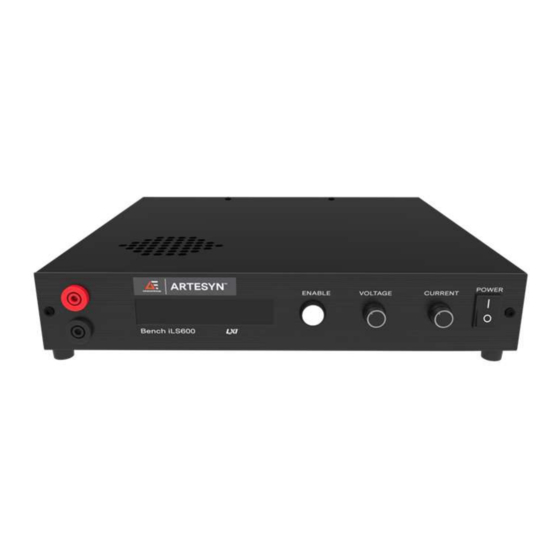
Advanced Energy's Artesyn iLS600, iLS600-R and iLS1500
series are programmable DC power supplies with a single
output that offers output power to 600 and 1500 watts. With
12-bit D/A & A/D converters embedded, the power supplies
come with the capability of reporting voltage and current very
accurately. The iLS600, iLS600-R and iLS1500 series provide
convenient digital rotary controls for voltage and current
adjustment and the power supplies also come with rear ports
that allow remote control via USB, Ethernet, and analog
control inputs. The iLS600, iLS600-R and iLS1500 series are
LXI certified.
AT A GLANCE
Total Power
600 and 1500 Watts
# of Outputs
Single
©2021 Advanced Energy Industries, Inc.
Advertisement
Table of Contents

Related Manuals for Advanced Energy iLS600 Series

Summary of Contents for Advanced Energy iLS600 Series
- Page 1 Series Intelligent Laboratory Power 600W/1500W Programming Manual Advanced Energy’s Artesyn iLS600, iLS600-R and iLS1500 AT A GLANCE series are programmable DC power supplies with a single output that offers output power to 600 and 1500 watts. With 12-bit D/A &...
-
Page 2: Table Of Contents
iLS600, iLS600-R and iLS1500 Series TABLE OF CONTENTS SECTION DESCRIPTION PAGE OPERTATING MODES Bench iLS Operating Modes 1.0.1 Local 1.0.2 Remote 1.0.3 Remote with Lock 1.0.4 Analog Voltage Control 1.0.5 Analog Current Control 1.0.6 Analog Dual Control 1.0.7 Parallel Mode 1.0.8 Series Mode 1.0.9... - Page 3 iLS600, iLS600-R and iLS1500 Series TABLE OF CONTENTS SECTION DESCRIPTION PAGE 1.5.4 Remote Queries 1.5.5 Additional SCPI Commands 1.5.6 Additional Capabilities Analog Dual Control Mode 1.6.1 Voltage Setpoint 1.6.2 Current Setpoint 1.6.3 Activating/Deactivating the Output 1.6.4 Remote Queries 1.6.5 Additional SCPI Commands 1.6.6 Additional Capabilities REMOTE SENSE CONFIGURATION...
- Page 4 iLS600, iLS600-R and iLS1500 Series TABLE OF CONTENTS SECTION DESCRIPTION PAGE 6.0.8 SCPI Access 6.0.9 Questionable Status Fan-Out Registers 6.0.10 Temperature Status Register 6.0.11 Hardware Status Register 6.0.12 Operation Status Register 6.0.13 Standard Event Status Register 6.0.14 Error/Event Queue 6.0.15 Error Condition Register 6.0.16 Status Byte Register and Service Request Enable Register...
-
Page 5: Opertating Modes
iLS600, iLS600-R and iLS1500 Series SECTION 1 OPERATING MODES 1.0 Bench iLS Operating Modes 1.0.1 Local In Local mode, the user controls BENCH iLS via the front panel. While in Local mode the user can achieve nearly full capability via the SCPI command interface, EXCEPT for setting operational voltage and current setpoints and activating the output. -
Page 6: Analog Dual Control
iLS600, iLS600-R and iLS1500 Series SECTION 1 OPERATING MODES 1.0.6 Analog Dual Control In Analog Dual Control mode, the output current setpoint is provided by the Analog Current input to the Interface board and the output voltage setpoint is provided by the Analog Voltage input to the Interface board. -
Page 7: Mode Transitions Commanded Via Remote Scpi Command
iLS600, iLS600-R and iLS1500 Series SECTION 1 OPERATING MODES Selecting the No option will not cancel the selection – it will just not store the selection to non-volatile memory. To discard the new selection, the user must return to the Control Source option and re-select the original mode. -
Page 8: Local Mode
iLS600, iLS600-R and iLS1500 Series SECTION 1 OPERATING MODES 1.1 Local Mode In Local Mode, you will control BENCH iLS primarily using the front panel controls. However, many SCPI commands are still available – only setting of setpoints and activating the output are disallowed. -
Page 9: Remote Mode
iLS600, iLS600-R and iLS1500 Series SECTION 1 OPERATING MODES 1.2 Remote Mode In Remote Mode, you will control BENCH iLS using SCPI commands. You will also have limited control available via the front panel 1.2.1 SCPI Commands In the following list of available SCPI commands, OUTPut <ON|OFF>... -
Page 10: Additional Capabilities
iLS600, iLS600-R and iLS1500 Series SECTION 1 OPERATING MODES 1.2.3 Additional Capabilities When the output is OFF, you can switch operating modes, as described in Section 1.0. When the output is OFF, you can configure Remote Sense, as described in Section 2.0. When the output is OFF, you can execute unit Calibration, as described in Section 3.0. -
Page 11: Current Setpoint
iLS600, iLS600-R and iLS1500 Series SECTION 1 OPERATING MODES 1.4.2 Current Setpoint The Current Setpoint is the last current value set when in Local Mode, and once in Analog Voltage Control Mode, cannot be changed either from the front panel or by a SCPI command. -
Page 12: Analog Current Control Mode
iLS600, iLS600-R and iLS1500 Series SECTION 1 OPERATING MODES 1.5 Analog Current Control Mode 1.5.1 Current Setpoint When the unit is in Analog Current Control Mode, the Analog Current channel supplies the Current Setpoint. Scaling: You can select 3 volt, 5 volt, or 10 volt scaling for the analog current input. This is the value which represents the maximum model-specific current. -
Page 13: Additional Scpi Commands
iLS600, iLS600-R and iLS1500 Series SECTION 1 OPERATING MODES VOLTage? Query voltage setpoint (volts) CURRent? Query current setpoint (amps) POWer? Query power setpoint (watts) Voltage is returned in volts, current in amperes, and power in watts. The output state is either ON or OFF. -
Page 14: Current Setpoint
iLS600, iLS600-R and iLS1500 Series SECTION 1 OPERATING MODES 1.6.2 Current Setpoint When the unit is in Analog Dual Control Mode, the Analog Current channel supplies the Current Setpoint. Analog Input Scaling: You can select 3 volt, 5 volt, or 10 volt scaling for the analog current input. This is the value which represents the maximum model-specific current. -
Page 15: Additional Scpi Commands
iLS600, iLS600-R and iLS1500 Series SECTION 1 OPERATING MODES 1.6.5 Additional SCPI Commands Regardless of the output state, you can query Status and Error registers, as described in Section 6.0. 1.6.6 Additional Capabilities When the output is OFF, you can switch operating modes, as described in Section 1.0. When the output is ON, you will be able to execute only those commands which activate and deactivate the output and measure the output voltage and current. -
Page 16: Remote Sense Configuration
iLS600, iLS600-R and iLS1500 Series SECTION 2 REMOTE SENSE CONFIGURATION 2.0 Enable/Disable BENCH iLS Remote Sense You can enable or disable the BENCH iLS Remote Sense capability and set the lead resistance with the following SCPI commands. RSENSE Enable/disable Remote Sense RSENSE? Return Remote Sense state RSENSE:RESistance... -
Page 17: Calibration
iLS600, iLS600-R and iLS1500 Series SECTION 3 CALIBRATION You can calibrate BENCH iLS over the SCPI command interface. To do so you must execute a series of steps while opening and shorting the output. These steps may be performed via the front panel or via SCPI commands. - Page 18 iLS600, iLS600-R and iLS1500 Series SECTION 3 CALIBRATION 10)Command BENCH iLS to perform the current calibration based on the recorded values: CALibration:CALCulate:CURRent <low current setpoint>,<low current measured>,<high current setpoint>,<high current measured> All current must be in Amperes. advancedenergy.com Rev. 05.20.21_#1.0...
-
Page 19: Self-Test
iLS600, iLS600-R and iLS1500 Series SECTION 4 SELF-TEST BENCH iLS executes Self-Test as part of its power-up sequence. In addition, you may exercise a number of Self-Test options with the following SCPI commands: *TST? Execute Self-Test and return the results. TEST:SELFtest[:EXECute] Same as above TEST:QUERy? -
Page 20: Miscellaneous Commands
iLS600, iLS600-R and iLS1500 Series SECTION 5 MISCELLANEOUS COMMANDS BENCH iLS recognizes a number of miscellaneous SCPI commands. 5.0 *CLS *CLS clears the Event registers of the Questionable Status, Operation Status, Temperature Status, and Hardware Status Register structures, in addition to the Error/Event Queue. 5.1 *IDN? *IDN? returns the identification string for this unit. -
Page 21: Status And Errors
iLS600, iLS600-R and iLS1500 Series SECTION 6 STATUS AND ERRORS 6.0 Architecture Figure 1 shows the Overall Status Architecture. Each section will then be discussed in greater detail. Figure 1: Overall Status Architecture advancedenergy.com Rev. 05.20.21_#1.0... -
Page 22: Over-Voltage Error
iLS600, iLS600-R and iLS1500 Series SECTION 6 STATUS AND ERRORS Figure 2 shows the Questionable Status Register Figure 2: Questionable Status Register The Questionable Status Register takes the standard SCPI structure. The seven individual condition inputs are: 6.0.1 Over-Voltage Error When activated, the unit has exceeded the Over-Voltage Protection limit. -
Page 23: Watchdog Error
iLS600, iLS600-R and iLS1500 Series SECTION 6 STATUS AND ERRORS 6.0.5 Watchdog Error A watchdog timeout has occurred and the processor has restarted itself. 6.0.6 Self-Test Error A self-test error has occurred. Self-test is run automatically at power-up and can additionally be commanded remotely. -
Page 24: Temperature Status Register
iLS600, iLS600-R and iLS1500 Series SECTION 6 STATUS AND ERRORS 6.0.10 Temperature Status Register Figure 3 shows the Temperature Status Register. It also takes the standard SCPI structure. Figure 3: Temperature Status Register Output Board Over-Temperature The output board temperature surpasses its allowed operating limit. Primary Board Over-Temperature The primary board temperature surpasses its allowed operating limit. -
Page 25: Hardware Status Register
iLS600, iLS600-R and iLS1500 Series SECTION 6 STATUS AND ERRORS 6.0.11 Hardware Status Register Figure 4 shows the Temperature Status Register. It also takes the standard SCPI structure. Figure 4: Temperature Status Register The Hardware Status Register four individual condition inputs are: 12V Bias Error The internal 12V bias is either too low or too high for valid operation. -
Page 26: Operation Status Register
iLS600, iLS600-R and iLS1500 Series SECTION 6 STATUS AND ERRORS SCPI Access Access to the Temperature Status Register is via the following commands: STATus:QUEStionable:HARDware[:EVENt]? Rtn Event register STATus:QUEStionable:HARDware:CONDition? Rtn Condition register STATus:QUEStionable:HARDware:ENABle <value> Set Enable register STATus:QUEStionable:HARDware:ENABle? Rtn Enable register 6.0.12 Operation Status Register Figure 5 shows the Operation Status Register. - Page 27 iLS600, iLS600-R and iLS1500 Series SECTION 6 STATUS AND ERRORS Output Activated This is the indication that the output is currently activated. Constant Voltage The output is in its constant voltage mode, where voltage is held constant at a specified setpoint and current will vary dependent on load.
-
Page 28: Standard Event Status Register
iLS600, iLS600-R and iLS1500 Series SECTION 6 STATUS AND ERRORS 6.0.13 Standard Event Status Register Figure 6 shows the Standard Event Status Register. Figure 6: Standard Event Status Register The Standard Event Status Register takes the standard SCPI structure. The eight individual condition inputs are: Operation Complete This bit is not used by BENCH iLS. -
Page 29: Error/Event Queue
iLS600, iLS600-R and iLS1500 Series SECTION 6 STATUS AND ERRORS Command Error This bit is not used by BENCH iLS. User Request This bit is not used by BENCH iLS. Power On This bit is not used by BENCH iLS. SCPI Access Access to the Standard Event Status Register is via the following commands: *ESR? - Page 30 iLS600, iLS600-R and iLS1500 Series SECTION 6 STATUS AND ERRORS –131 “Invalid suffix” –134 “Suffix too long” –200 “Execution error” –201 “Invalid while in local” –221 “Settings conflict” –222 “Data out of range” –234 “Insufficient data” –350 “Queue overflow” “Over current” “Over voltage”...
-
Page 31: Error Condition Register
iLS600, iLS600-R and iLS1500 Series SECTION 6 STATUS AND ERRORS SCPI Access Access to the Error/Event Queue is via the following commands: SYSTem:ERRor[:NEXT]? Return the next queue entry SYSTem:ERRor:COUNt? Return the present number of queue entries SYSTem:ERRor:CLEar Clear the queue 6.0.15 Error Condition Register Associated with the Error/Event Queue is a 16-bit Error Condition Register. -
Page 32: Status Byte Register And Service Request Enable Register
iLS600, iLS600-R and iLS1500 Series SECTION 6 STATUS AND ERRORS SCPI Access To view the Error Condition Register, use the SCPI command: SYSTem:ERRor:CONDition? Return the error condition register 6.0.16 Status Byte Register and Service Request Enable Register Figure 7 shows the Status Byte Register and the Service Request Enable Register. Figure 7: Status Byte Register The six individual condition inputs of the Status Byte Register are: Error/Event Queue... - Page 33 iLS600, iLS600-R and iLS1500 Series SECTION 6 STATUS AND ERRORS Message Available (MAV) As BENCH iLS does not initiate any message, this bit is not used. Standard Event Status If a Standard Event has occurred and is enabled to feed the Status Byte Register, this bit will be set.
-
Page 34: Drivers
iLS600, iLS600-R and iLS1500 Series SECTION 7 DRIVERS Installation of either a USB then a Labview or an IVI driver is the first step towards using the power supply with Labview. If the user plans on only using Labview the Labview driver will suffice. - Page 35 iLS600, iLS600-R and iLS1500 Series SECTION 7 DRIVERS 2) On the Driver tab select Update Driver. 3) Select Browse my computer for driver software. advancedenergy.com Rev. 05.20.21_#1.0...
- Page 36 iLS600, iLS600-R and iLS1500 Series SECTION 7 DRIVERS 4) Select Browse. On the Browse for screen locate where the Bench USB Driver was extracted to and click next. 5) On Windows Security select Install. advancedenergy.com Rev. 05.20.21_#1.0...
- Page 37 iLS600, iLS600-R and iLS1500 Series SECTION 7 DRIVERS 6) Once the driver has been successfully installed windows will verify the installation and the Bench can now be accessed through USB communication. 7) Device manager will show the unit as follows. advancedenergy.com Rev.
-
Page 38: Ivi Drivers
iLS600, iLS600-R and iLS1500 Series SECTION 7 DRIVERS 7.1 IVI Drivers To improve users' experience when they combine drivers and other software from various vendors, it is important to have some key software components common to all implementations. In order to accomplish this, the IVI Foundation provides a standard set of shared components that must be used by all compliant drivers and ancillary software. -
Page 39: Labview Drivers
iLS600, iLS600-R and iLS1500 Series SECTION 7 DRIVERS After installing the Artesyn Power drivers additional documentation may be found in your local drive in the folder: C:\ProgramData\Microsoft\Windows\Start Menu\Programs\Artesyn Power\ArtesynPowerDC. 7.2 LabView Drivers Prior to installing the LabView drivers LabView itself must be installed on your machine. Once LabView is installed, to install the Artesyn Power LabView Drivers download them from: https://artesynpower.com/drivers/ (or the National Instruments website) then unzip the files and copy to your local directory: C:\Program Files (x86)\National... -
Page 40: Appendix
iLS600, iLS600-R and iLS1500 Series APPENDIX SCPI Commands *CLS — This command clears the following registers: • The Standard Event Status Register • The Event register of the Questionable Status Register structure. • The Event register of the Operation Status Register structure. •... - Page 41 iLS600, iLS600-R and iLS1500 Series APPENDIX • Temperature Error Output Board Over-Temperature Primary Board Over-Temperature Fan stall • Watchdog Error Execution Error (not used) Command Error (not used) User Request (not used) Power On (not used) The command *ESE 0 clears this register. *ESE? —...
- Page 42 iLS600, iLS600-R and iLS1500 Series APPENDIX *OPC? — This command responds with an indication of whether the current operation is complete. Because this unit does not support concurrent command execution, this command will always return the value 1. *RST — This command executes a soft reset of the system. The output is deactivated, all error Conditions are cleared (however, error Events are not), and the unit is returned to its Output Off state.
- Page 43 iLS600, iLS600-R and iLS1500 Series APPENDIX Summary Bit (RQS) Operation Status *TST? — This command processes the Self-Test command, executing the unit selftest and returning the results. This command is identical to the command “TEST:SELFtest[:EXECUT]” The returned results are: No self-test error Output Voltage/Current ADC failed *WAI —...
- Page 44 iLS600, iLS600-R and iLS1500 Series APPENDIX OUTPut:AUTOstart? — This command returns the present configuration auto-start flag. The returned value will be either ON or OFF. OUTPut[:STATe] <ON|OFF> — This command activates (ON) or deactivates (OFF) the unit output. OUTPut[:STATe]? — This command returns the present output activation state, ON or OFF. RSENse <ON|OFF>...
- Page 45 iLS600, iLS600-R and iLS1500 Series APPENDIX [SOURce:]CURRent[:LEVel][:IMMediate][:AMPLitude] <MIN|MAX| value> — This command sets the Current setpoint as specified. The setpoint can be set to MIN (0.0 amperes), MAX (model-specific maximum current), or a specified value, in amperes. DEF is accepted but ignored. [SOURce:]CURRent[:LEVel][:IMMediate][:AMPLitude]? —...
- Page 46 iLS600, iLS600-R and iLS1500 Series APPENDIX [SOURce:]VOLTage[:LEVel][:IMMediate][:AMPLitude]? — This command returns the present Voltage setpoint, in volts. [SOURce:]VOLTage:PROTectection[:LEVel] <value> — This command sets the over- voltage protection threshold to value, which is specified in volts. Note: If storage of this threshold to non-volatile memory is desired, SYSTem:CONFiguration:SAVE must also be executed.
- Page 47 iLS600, iLS600-R and iLS1500 Series APPENDIX STATus:OPERation:ENABle <value> — This command sets the Operation Status Enable Register to the specified value. The value is specified in decimal form described in the description of “STATus:OPERation:CONDition?”. A value 0 clears all Enables. STATus:OPERation:ENABle? —...
- Page 48 iLS600, iLS600-R and iLS1500 Series APPENDIX 4096 Output Error 8192 Instrument Summary Bit (not used) 16384 Command Warning (not used) STATus:QUEStionable:ENABle <value> — This command sets the Questionable Status Enable Register to the specified value. The value is specified in decimal form described in the description of “STATus:QUEStionable:CONDition?”.
- Page 49 iLS600, iLS600-R and iLS1500 Series APPENDIX STATus:QUEStionable:HARDware:ENABle? — This command returns the Questionable Status Hardware Enable Register contents. The returned value is in decimal form described in the description of “STATus:QUEStionable:HARDware:CONDition?”. If multiple bits are set, the result is the sum of the set bit values. STATus:QUEStionable:HARDware[:EVENt]? —...
- Page 50 iLS600, iLS600-R and iLS1500 Series APPENDIX SYSTem:AOUTput:MODE <DISabled|PARallel|SERies> — This command controls the function of the analog output of the power supply to facilitate series or parallel operation. In parallel mode the analog output is proportional to the output current of the power supply, in series mode the analog output is proportional to the output voltage of the power supply.
- Page 51 iLS600, iLS600-R and iLS1500 Series APPENDIX • Remote sense lead resistance • Master mode • Unit serial number • LAN configuration This command can be executed from any of the six operating modes (Local, Remote, Remote with Lock, Analog Voltage Control, Analog Current Control, or Analog Dual Control), but only when the output is deactivated.
- Page 52 iLS600, iLS600-R and iLS1500 Series APPENDIX SYSTem:MODe:ASCale? — This command returns the presently selected scaling level of the specified analog channel (voltage or current). SYSTem:ERRor:CLEar — This command clears the Error/Event Queue. SYSTem:ERRor:CONDition? — This command returns the present Error Conditions state. Contents consist of: Over-Current Error Over-Voltage Error...
- Page 53 iLS600, iLS600-R and iLS1500 Series APPENDIX SYSTem:PROMpt <ON|OFF> — This command enables (ON) or disables (OFF) the SCPI prompt. The prompt is a newline (0x0A) character. SYSTem:VERSion? — This command returns the version of the SCPI specification which is supported. For BENCH iLS, the string 1999.0 is returned. TEST:SELFtest:CLE —...
- Page 54 For international contact information, visit advancedenergy.com. Specifications are subject to change without notice. Not responsible for errors or omissions. ©2020 Advanced Energy Industries, Inc. All rights powersales@aei.com (Sales Support) reserved. Advanced Energy®, and AE® are U.S. trademarks productsupport.ep@aei.com (Technical Support) of Advanced Energy Industries, Inc.
Need help?
Do you have a question about the iLS600 Series and is the answer not in the manual?
Questions and answers