Table of Contents
Advertisement
Quick Links
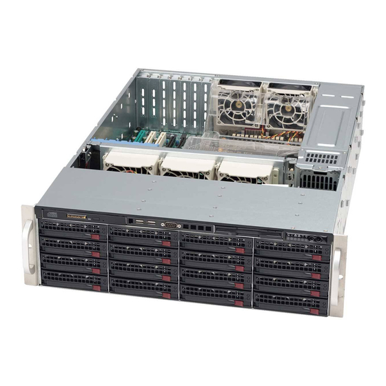
SC836 Chassis Series
SC836BE1C-R1K03B
SC836BHA-R1K28B
SC836BHE26-R1K28B
SC836BE26-R1K28B
SC836BE16-R920B
SC836BA-R920B
SC836E16-R500B
SC836E26-R1200B
SC836BE1C-R1K23B
SC836TQ-R800V / SC836TQ-R800B
USER'S MANUAL
SC836BE2C-R1K03B
SC836BHE16-R1K28B
SC836BE16-R1K28B
SC836BA-R1K28B
SC836BE26-R920B
SC836TQ-R500B
SC836E16-R1200B
SC836A-R1200B
SC836TQ-R710B
Revision 2.2
Advertisement
Table of Contents


Need help?
Do you have a question about the SC836BE1C-R1K23B and is the answer not in the manual?
Questions and answers