Table of Contents
Advertisement
Quick Links
Advertisement
Chapters
Table of Contents

Subscribe to Our Youtube Channel
Related Manuals for Supermicro SC818


Summary of Contents for Supermicro SC818
- Page 1 ® UPER The SC818 Chassis Series User Guide Rev. 1.0...
- Page 2 Clara County in the State of California, USA. The State of California, County of Santa Clara shall be the exclusive venue for the resolution of any such disputes. Supermicro's total liability for all claims will not exceed the price paid for the hardware product.
-
Page 3: Table Of Contents
Chapter 2: Installation Procedures ..........2-1 Section 1: Installing components into the SC818 Chassis ... 2-1 A. Removing the Top Cover of the SC818 Chassis ......... 2-1 B. Removing the Riser Card Bracket from the Chassis ......... 2-2 C. Installing the Motherboard into the Chassis ..........2-3 D. -
Page 4: Chapter I: Introduction
SC818 Chassis User's Guide Chapter 1- Introduction A. Safety Guidelines A-1 Electricity Safety General Electrical Safety Guidelines • Use the exact type of power cords as required. • Be sure to use power cord(s) that came with safety certifi ca- tions. - Page 5 4. Be sure to lock to the chassis or the system to prevent unauthorized access. 5. Please follow the procedures listed in Chapter 2 to install or remove components to or from the SC818. A-5. An Important Note to the User: All images and graphics shown in this manual were based upon the latest chas- sis Revision available at the time of publishing.
-
Page 6: Packing Lists
SC818 Chassis User's Guide B. Packing Lists B-1. The SC818+-1000 Chassis Packaging List: The SC818+-1000 Chassis Packing List Item Name Part Number Q'ty Notes Chassis body CSE-818TS+-1000 *Power supply PWS-1K01-1R 1 1000W *Cooling fan (Chassis fan) FAN-0086 6 40x56 (Nidec) Dual blade 3 pin... - Page 7 Chapter 1: Introduction B-3. The SC818-1000 Chassis Packaging List: The SC818 1000 Chassis Packing List Item Name Part Number Q'ty Notes Chassis body CSE-818 1000 *Power supply PWS-1K01-1R 1 1000W *Cooling fan (Chassis fan) FAN-0086 6 40x56 (Nidec) Dual blade 3 pin...
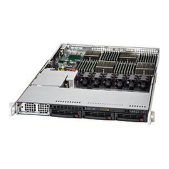
- Page 8 SC818 Chassis User's Guide C. The SC818 Chassis Front Panel Top View C-1. Major Chassis Components 1. Front Control Panel (*See C-2 below) 2. Power Module 6. Chipset 3. Power Back Plane 7. DDR Memory Modules (8) 4. Fan Modules (6) 5.
- Page 9 Chapter 1: Introduction C-3. Front Panel LED Indicators 1. Power Button 2. Reset Button 3. Power-on LED 4. Hard Drive Activity LED 5. LAN Port1 LED 6. LAN Port2 LED 7. Overheat/Fan Fail LED C-4. Front Panel LED Descriptions LED Button Color Condition Description...
-
Page 10: The Sc818 Chassis Specifi Cations
SC818 Chassis User's Guide D. The SC818 Chassis Specifi cations D-1. The SC818+-1000 Chassis Specifi cations Model SC818S+-1000 SC818TQ+-1000 1U Rackmount 1U Rackmount Form Factor AMD Quad Opteron AMD Quad Opteron CPU Support Processors Processors ATX 13” x 16” ATX 13” x 16”... -
Page 11: The Sc818 Chassis Power Supply Specifi Cations
Chapter 1: Introduction E. The SC818 Chassis Power Supply Specifi cations Power Supply Spec SC818 Mfr. Model # PWS-1K01-1R Mfr. Part # PWS-1K01-1R Rated AC Input Voltage 100-240 VAC Rated Input Frequency 50-60 Hz Rated Input Current 15A (115V) 10A (230V) - Page 12 SC818 Chassis User's Guide Notes 1-12...
-
Page 13: Chapter 2: Installation Procedures
Chapter 2: Installation Procedures Chapter 2: Installation Procedures Section 1: Installing Components into the SC818 A. Removing the Top Cover from the Chassis Before installing any components, replacing chassis fans or accessing the mother- board, you will fi rst need to remove the top cove from the chassis. -
Page 14: Removing The Riser Card Bracket From The Chassis
SC818 Chassis User's Guide B. Removing the Riser Card Bracket from the Chassis Before installing the motherboard, you will need to remove the riser card bracket from the chassis. Procedures 1. After the top cover is removed from the chassis, using a Philips screw driver to remove the two screws on the riser card bracket as shown below: 2. -
Page 15: Installing The Motherboard Into The Chassis
Chapter 2: Installation Procedures C. Installing the Motherboard into the Chassis After you've removed the chassis cover and the riser card bracket from the chassis, you are ready to install the motherboard into the chassis. Procedures 1. Locate the mounting holes on the motherboard and the mounting holes on the chassis. - Page 16 SC818 Chassis User's Guide 4. Connect power cables to the power connectors on the motherboard as shown below. 5. Connect fan cables to the fan headers on the motherboard as shown in the picture below.) Fan Headers Power Connectors...
-
Page 17: Installing The Chipset Air Shroud Into The Chassis
Chapter 2: Installation Procedures D. Installing the Chipset Air Shroud into the Chassis After the MB is securely installed into the chassis, you will need to install the chipset air shroud to prevent the chipset from overheat. Procedures 1. Align the chipset air shroud with the chipset. 2. -
Page 18: Installing The Cpu Air Shroud Into The Chassis
SC818 Chassis User's Guide E. Installing the CPU Air Shroud into the Chassis After you have installed the CPU and the CPU Heatsink into the chassis, you will need to install the CPU air shroud to prevent the processors from overheat. -
Page 19: Accessing The Hard Disk Drive Tray And Installing A Hard Drive
Chapter 2: Installation Procedures F. Accessing the Hard Disk Drive Tray and Installing a Hard Drive To install a hard disk drive into the chassis, you need to fi rst remove the HDD tray from the chassis so that the HDD can be installed in. Procedures 1. -
Page 20: Rail Installation
SC818 Chassis User's Guide G. Rail Installation Rail Packaging includes: *One pair of inner slides to be installed on the chassis *One pair of outer slides to be installed in the rack *One pair of long brackets to be used on the rear side of the outer slides *Two pairs of short brackets to be used on the front side of the outer slides (Note: One pair of short brackets include screw threads, and the other pair does not. - Page 21 Chapter 2: Installation Procedures G-3 Installing the Slide Assemblies to the Rack Procedures 1. After you have installed the short and long brackets to the outer slides, you are ready to install the whole slide assemblies (-outer slides with short and long brackets attached) to the rack.
-
Page 22: Installing The Chassis Into The Rack
SC818 Chassis User's Guide H. Installing the Chassis into the Rack Procedures 1. Push the inner slides, which are attached to the chassis, into the grooves of the outer slide assemblies that are installed in the rack as shown below: 2. -
Page 23: Section 2: Scsi (Super) Gem Driver Installation Instructions For The Windows Operating System
6) Click “Next” 2 times, uncheck both “Floppy disk drives” and “CD-ROM drives”. Then, select the item- “Specify a location,” and choose “Next”. 7) Click on “Browse” and choose D drive or wherever Supermicro Setup CD is 8) Choose “Qlogic” folder and click on “Open”. - Page 24 SC818 Chassis User's Guide Notes 2-12...
- Page 25 Aappendix UPER ® SCA818S Backplane USER'S GUIDE Rev. 1.0...
- Page 26 SCA818S Backplane User’s Guide Table of Contents Safety Information and Technical Specifi cations ......... A-3 1. Safety Guidelines ..................A-3 2. Introduction to the SCA818S Backplane ..........A-4 3. Jumper Settings and Pin Defi nitions .............A-5 A. Front Connectors and Jumpers ............A-5 A-1.
-
Page 27: Safety Information And Technical Specifi Cations
Safety Information and Technical Specifi cations Safety Information and Technical Specifi cations 1. Safety Guidelines To avoid personal injury and property damage, please carefully follow all the safety steps listed below when accessing your system or handling the components: ESD Safety Guidelines Electric Static Discharge (ESD) can damage electronic com ponents. -
Page 28: Jumper Settings And Pin Defi Nitions
SCA818S Backplane User’s Guide 2. Jumper Settings and Pin Defi nitions A. Front Jumpers and Connectors Front Jumper/Connector Locations JP17 JP18 SCA818S UPER JP19 +12V JP22 +12V JP20 JP21 JP23 Front View (*See below for front connector/jumper descriptions.) A-2. Front Panel Connectors A. - Page 29 Safety Information and Technical Specifi cations B: Ultra 320 SCSI Connector (LVD1) SCSI Connector Pin Defi nitions Ultra320 SCSI Drive Connector Pin Defi nitions (J28) There is a Ultra 320 Pin# Defi nition Pin # Defi nition SCSI connector, marked +DB (12) -DB (12) "B"...
- Page 30 SCA818S Backplane User’s Guide D: GEM 318 (SAF-TE: SCSI Accessed Fault-Tolerant Enclosures) This chip allows the system to use a set of pre-defi ned SCSI commands to monitor the status of disk drives and provide disk drive information to the user through LED indicators and buzzers.
- Page 31 Safety Information and Technical Specifi cations A-2. Backplane Front Jumpers Front Jumper Descriptions and Pin Defi nitions Jumper Description Definition JP17 On (*Default) Buzzer Enable Buzzer Disable JP18 Delay Start-SCA#0 Enable Off (*Default) Delay Start-SCA#0 Disable JP20 Remote Start-SCA#0 Enable Off (*Default) Remote Start-SCA#0 Disable JP22...
-
Page 32: Rear Connectors And Led Indicators
SCA818S Backplane User’s Guide B. Rear Connectors and LED Indicators B-1 Rear Connector/LED Indicator Locations Rear View SCA2 SCA4 SCA1 SCA#0 SCA#1 SCA#2 (*See below for rear connector/LED descriptions.) B-2 Connector/LED Indicator Descriptions B-2.1 Backplane Rear Connectors Rear Specification Connector SCA1 (Rear) SCSI HDD#0 (SCA#0) SCA4 (Rear)
Need help?
Do you have a question about the SC818 and is the answer not in the manual?
Questions and answers