Table of Contents
Advertisement
Quick Links
SC825 CHASSIS Series
SC825TQC-R740WB
SC825TQ-R740WB
SC825TQ-R740LPB
SC825TQ-R720LPB
SC825TQ-R720UB
SC825TQ-R700U(V)(B)
SC825TQ-600LPB
SC835TQ-600WB
SC825TQ-560LP(V)(B)
SC825TQ-R500WB
USER'S MANUAL
SC825TQC-R1K03WB
2.0c
SC825TQC-R1K03LPB
SC825TQC-R740LPB
SC825TQ-R740UB
SC825TQ-710LP
SC825TQ-R700LP(V)(B)
SC825TQC-600LPB
SC825TQC-600WB
SC825TQ-563UB
SC825TQ-563LPB
SC825TQ-560U(V)(B)
Advertisement
Table of Contents

Related Manuals for Supermicro SC825TQ-R700B


Summary of Contents for Supermicro SC825TQ-R700B
- Page 1 SC825 CHASSIS Series SC825TQC-R1K03WB SC825TQC-R740WB SC825TQC-R1K03LPB SC825TQ-R740WB SC825TQC-R740LPB SC825TQ-R740LPB SC825TQ-R740UB SC825TQ-R720LPB SC825TQ-710LP SC825TQ-R720UB SC825TQ-R700LP(V)(B) SC825TQ-R700U(V)(B) SC825TQC-600LPB SC825TQ-600LPB SC825TQC-600WB SC835TQ-600WB SC825TQ-563UB SC825TQ-560LP(V)(B) SC825TQ-563LPB SC825TQ-R500WB SC825TQ-560U(V)(B) USER’S MANUAL 2.0c...
- Page 2 This product, including software and documentation, is the property of Supermicro and/or its licensors, and is supplied only under a license. Any use or reproduction of this product is not allowed, except as expressly permitted by the terms of said license.
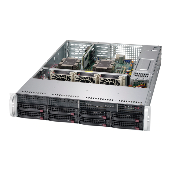
- Page 3 SC825 2U chassis. Installa- tion and maintenance should be performed by experienced technicians only. Supermicro’s SC825 2U chassis features a unique and highly optimized design. The chassis is equipped with a 560W (single), 563W (single) 600W (single), 700W (redundant) 710W (single), 720W (redundant), 740W (redundant) or 1000W (redun- dant) high-efficiency power supply for superb power savings.
- Page 4 SC825 Chassis Manual Manual Organization Chapter 1 Introduction The first chapter provides a checklist of the main components included with this chassis and describes the main features of the SC825 chassis. This chapter also includes contact information. Chapter 2 Standardized Warning Statements for AC Systems This chapter lists warnings, precautions, and system safety.
-
Page 5: Table Of Contents
Hard Drives ..................... 1-3 PCI Expansion slots ..................1-3 Peripheral Drives ..................... 1-3 Other Features ....................1-3 Contacting Supermicro ..................1-4 Returning Merchandise for Service..............1-5 Chapter 2 Standardized Warning Statements for AC Systems About Standardized Warning Statements ............2-1 Warning Definition ................... - Page 6 SC825 Chassis Manual Chapter 4 System Interface Overview ......................4-1 Control Panel Buttons ..................4-2 Control Panel LEDs ..................4-2 Drive Carrier LEDs ..................4-4 SAS/SATA Drives .................... 4-4 Chapter 5 Chassis Setup and Maintenance Overview ......................5-1 Installation and General Maintnenance ............5-1 Installation .......................
- Page 7 Preface Rack Mounting Considerations ............... 6-3 Ambient Operating Temperature ..............6-3 Reduced Airflow ..................6-3 Mechanical Loading ................... 6-3 Circuit Overloading ..................6-3 Reliable Ground ..................6-3 Rack Mounting Instructions ................6-4 Separating the Sections of the Rack Rails ............. 6-4 Installing the Inner Rail Extension ..............
- Page 8 SC825 Chassis Manual Notes viii...
-
Page 9: Chapter 1 Introduction
Chapter 1 Introduction Overview Supermicro’s SC825 2U chassis features a unique and highly-optimized design. The chassis is equipped with high efficiency power supply. Shipping List Please visit the following link for the latest shipping lists and part numbers for your particular chassis model www.supermicro.com... - Page 10 SC825 Chassis Manual SC825 Chassis SC825TQ-R700LPV/ 8x SAS/SATA 7x LP 700W (Redundant) SC825TQ-R700LPB SC825TQC-600LPB 8x SAS3/SATA 7x LP 600W (Platinum Level) SC825TQC-600WB 8x SAS3/SATA 4x FH + 3x LP 600W (Platinum Level) SC825TQ-600WB 8x SAS/SATA 4x FH + 3x LP 600W (Platinum Level) SC825TQ-600LPB 8x SAS/SATA...
-
Page 11: Chassis Features
Chapter 1: Introduction Chassis Features The SC825 2U, high-performance chassis includes the following features: Hard Drives The SC825 chassis features eight slots for SAS3 and SAS/SATA drives. These drives are hot-swappable. Once set up correctly, these drives can be removed with- out powering down the server. -
Page 12: Contacting Supermicro
Super Micro Computer, Inc. 980 Rock Ave. San Jose, CA 95131 U.S.A. Tel: +1 (408) 503-8000 Fax: +1 (408) 503-8008 Email: marketing@supermicro.com (General Information) support@supermicro.com (Technical Support) Website: www.supermicro.com Europe Address: Super Micro Computer B.V. Het Sterrenbeeld 28, 5215 ML... -
Page 13: Returning Merchandise For Service
For faster service, RMA authorizations may be requested online (http://www. supermicro.com/support/rma/). Whenever possible, repack the chassis in the original Supermicro carton, using the original packaging material. If these are no longer available, be sure to pack the chassis securely, using packaging material to surround the chassis so that it does not shift within the carton and become damaged during shipping. - Page 14 SC825 Chassis Manual Notes...
-
Page 15: Chapter 2 Standardized Warning Statements For Ac Systems
The following statements are industry standard warnings, provided to warn the user of situations which have the potential for bodily injury. Should you have questions or experience difficulty, contact Supermicro's Technical Support department for assistance. Only certified technicians should attempt to install or configure components. - Page 16 SC825 Chassis Manual Warnung WICHTIGE SICHERHEITSHINWEISE Dieses Warnsymbol bedeutet Gefahr. Sie befinden sich in einer Situation, die zu Verletzungen führen kann. Machen Sie sich vor der Arbeit mit Geräten mit den Gefahren elektrischer Schaltungen und den üblichen Verfahren zur Vorbeugung vor Unfällen vertraut.
- Page 17 Warning Statements for AC Systems جسذٌة اصابة ًتتسبب ف حالة ٌوكي أى ًاًك ف خطز ًٌٌع هذا الزهز !تحذٌز الذوائز بالوخاطز الٌاجوة عي ي على علن ، ك هعذات تعول على أي قبل أى الكهزبائٍة حىادث أي وقىع وٌع ل الىقائٍة...
-
Page 18: Installation Instructions
SC825 Chassis Manual Installation Instructions Warning! Read the installation instructions before connecting the system to the power source. 設置手順書 システムを電源に接続する前に、 設置手順書をお読み下さい。 警告 将此系统连接电源前,请先阅读安装说明。 警告 將系統與電源連接前,請先閱讀安裝說明。 Warnung Vor dem Anschließen des Systems an die Stromquelle die Installationsanweisungen lesen. ¡Advertencia! Lea las instrucciones de instalación antes de conectar el sistema a la red de alimentación. -
Page 19: Circuit Breaker
Chapter 2: Warning Statements for AC Systems Circuit Breaker Warning! This product relies on the building's installation for short-circuit (overcurrent) protection. Ensure that the protective device is rated not greater than: 250 V, 20 A. サーキッ ト ・ ブレーカー この製品は、 短絡 (過電流) 保護装置がある建物での設置を前提としています。 保護装置の定格が250 V、... -
Page 20: Power Disconnection Warning
SC825 Chassis Manual 경고! 이 제품은 전원의 단락(과전류)방지에 대해서 전적으로 건물의 관련 설비에 의존합니다. 보호장치의 정격이 반드시 250V(볼트), 20A(암페어)를 초과하지 않도록 해야 합니다. Waarschuwing Dit product is afhankelijk van de kortsluitbeveiliging (overspanning) van uw electrische installatie. Controleer of het beveiligde aparaat niet groter gedimensioneerd is dan 220V, 20A. - Page 21 Chapter 2: Warning Statements for AC Systems ¡Advertencia! El sistema debe ser disconnected de todas las fuentes de energía y del cable eléctrico quitado de los módulos de fuente de alimentación antes de tener acceso el interior del chasis para instalar o para quitar componentes de sistema. Attention Le système doit être débranché...
-
Page 22: Equipment Installation
SC825 Chassis Manual Equipment Installation Warning! Only trained and qualified personnel should be allowed to install, replace, or service this equipment. 機器の設置 トレーニングを受け認定された人だけがこの装置の設置、 交換、 またはサービスを許可 されています。 警告 只有经过培训且具有资格的人员才能进行此设备的安装、更换和维修。 警告 只有經過受訓且具資格人員才可安裝、更換與維修此設備。 Warnung Das Installieren, Ersetzen oder Bedienen dieser Ausrüstung sollte nur geschultem, qualifiziertem Personal gestattet werden. -
Page 23: Restricted Area
Chapter 2: Warning Statements for AC Systems Waarschuwing Deze apparatuur mag alleen worden geïnstalleerd, vervangen of hersteld door geschoold en gekwalificeerd personeel. Restricted Area Warning! This unit is intended for installation in restricted access areas. A restricted access area can be accessed only through the use of a special tool, lock and key, or other means of security. -
Page 24: Battery Handling
SC825 Chassis Manual אזור עם גישה מוגבלת !אזהרה יש להתקין את היחידה באזורים שיש בהם הגבלת גישה. הגישה ניתנת בעזרת .)'כלי אבטחה בלבד (מפתח, מנעול וכד محظورة مناطق ٍنتركُبها ف هذه انىحذة تخصيص تم ،أداة خاصت من خالل استخذاو فقط محظورة... - Page 25 Chapter 2: Warning Statements for AC Systems Warnung Bei Einsetzen einer falschen Batterie besteht Explosionsgefahr. Ersetzen Sie die Batterie nur durch den gleichen oder vom Hersteller empfohlenen Batterietyp. Entsorgen Sie die benutzten Batterien nach den Anweisungen des Herstellers. Attention Danger d'explosion si la pile n'est pas remplacée correctement. Ne la remplacer que par une pile de type semblable ou équivalent, recommandée par le fabricant.
-
Page 26: Redundant Power Supplies
SC825 Chassis Manual Redundant Power Supplies Warning! This unit might have more than one power supply connection. All connections must be removed to de-energize the unit. 冗長電源装置 このユニッ トは複数の電源装置が接続されている場合があります。 ユニッ トの電源を切るためには、 すべての接続を取り外さなければなりません。 警告 此部件连接的电源可能不止一个,必须将所有电源断开才能停止给该部件供电。 警告 此裝置連接的電源可能不只一個,必須切斷所有電源才能停止對該裝置的供電。 Warnung Dieses Gerät kann mehr als eine Stromzufuhr haben. Um sicherzustellen, dass der Einheit kein trom zugeführt wird, müssen alle Verbindungen entfernt werden. -
Page 27: Backplane Voltage
Chapter 2: Warning Statements for AC Systems امداد الطاقة بوحدات عدة اتصاالت جهاز ال يكون لهذا قد الكهرباء عن وحدة ال لعسل كافة االتصاالت يجب إزالة 경고! 이 장치에는 한 개 이상의 전원 공급 단자가 연결되어 있을 수 있습니다. 이 장치에 전원을... -
Page 28: Comply With Local And National Electrical Codes
SC825 Chassis Manual מתח בפנל האחורי !הרה אז קיימת סכנת מתח בפנל האחורי בזמן תפעול המערכת. יש להיזהר במהלך .העבודה اللىحة أوالطاقة المىجىدة على التيار الكهزبائي مه خطز هناك هذا الجهاس خدمة كه حذرا عند يعمل النظام عندما يكىن 경고! 시스템이... -
Page 29: Product Disposal
Chapter 2: Warning Statements for AC Systems Attention L'équipement doit être installé conformément aux normes électriques nationales et locales. תיאום חוקי החשמל הארצי !אזהרה הציוד חייבת להיות תואמת לחוקי החשמל המקומיים והארציים התקנת المتعلقة المحلية والىطىية قىاويه يجب أن يمتثل لل الكهربائية... -
Page 30: Hot Swap Fan Warning
SC825 Chassis Manual Attention La mise au rebut ou le recyclage de ce produit sont généralement soumis à des lois et/ou directives de respect de l'environnement. Renseignez-vous auprès de l'organisme compétent. סילוק המוצר !אזהרה .חוקי המדינה סילוק סופי של מוצר זה חייב להיות בהתאם להנחיות ו القىانين... - Page 31 Chapter 2: Warning Statements for AC Systems Warnung Gefährlich Bewegende Teile. Von den bewegenden Lüfterblätter fern halten. Die Lüfter drehen sich u. U. noch, wenn die Lüfterbaugruppe aus dem Chassis genommen wird. Halten Sie Finger, Schraubendreher und andere Gegenstände von den Öffnungen des Lüftergehäuses entfernt. ¡Advertencia! Riesgo de piezas móviles.
-
Page 32: Power Cable And Ac Adapter
Verbindungskabeln, Stromkabeln und/oder Adapater, die Ihre örtlichen Sicherheitsstandards einhalten. Der Gebrauch von anderen Kabeln und Adapter können Fehlfunktionen oder Feuer verursachen. Die Richtlinien untersagen das Nutzen von UL oder CAS zertifizierten Kabeln (mit UL/CSA gekennzeichnet), an Geräten oder Produkten die nicht mit Supermicro gekennzeichnet sind. 2-18... - Page 33 םילבכב שמתשהל רוסיא םייק ,תוחיטבה יקוחו למשחה ירישכמב שומישה יקוחל םאתהב -ב םיכמסומהUL -ב ואCSA (( לש דוק םהילע עיפומ רשאכUL/CSA ילמשח רצומ לכ רובע י"ע םאתוה רשא רצומב קר אלא ,רחאSupermicro .דבלב تالباكلا ءارشب مق وأ ةددحملا وأ ةرفوتملا تاليصوتلا مادختساب مق ،جتنملا بيكرت دنع...
- Page 34 Het gebruik van niet geschikte Kabels en/of Adapters kan een storing of brand veroorzaken. Wetgeving voor Elektrische apparatuur en Materiaalveiligheid verbied het gebruik van UL of CSA -gecertificeerde Kabels (met UL/CSA in de code) voor elke andere toepassing dan de door Supermicro hiervoor beoogde Producten. 2-20...
-
Page 35: Chapter 3 Chassis Components
Each SC825 chassis comes with a 2U SAS/SATA backplane. For more information regarding compatible backplanes, view the appendices found at the end of this man- ual. In addition, visit our website for the latest information at www.supermicro.com. Fans The SC825 chassis supports three system fans. System fans for SC825 chassis are powered from the motherboard. -
Page 36: Power Supply
Supermicro Authorized Distributors/ System Integrators/Resellers. A list of Supermicro Authorized Distributors/System Integra- tors/Reseller can be found at: www.supermicro.com. Click the Where to Buy link. -
Page 37: Chapter 4 System Interface
Chapter 4: System Interface Chapter 4 System Interface Overview There are LEDs on the control panel and the drive carriers to keep you constantly informed of the over-all status of the system, as well as the activity and health of specific components. -
Page 38: Control Panel Buttons
SC825 Chassis Manual Control Panel Buttons There are two push-buttons located on the front of the chassis. These are (in order from left to right) a reset button and a power on/off button. • Reset: The reset button is used to reboot the system. •... - Page 39 Chapter 4: System Interface Information LED Status Description Continously on and red An overheat ocondition has occurred. (This may be caused by cable congestion.) Blinking red (1 Hz) Fan failure: check for an inoperative fan. Blinking red (0.25 Hz) Power failure: check for an inoperative power supply. Solid blue Local UID has been activated.
-
Page 40: Drive Carrier Leds
SC825 Chassis Manual Drive Carrier LEDs Your chassis uses SAS/SATA drives. SAS/SATA Drives Each SAS/SATA drive carrier has two LEDs. Green: Each Serial ATA drive carrier has a green LED. When illuminated, this green LED (on the front of the SATA drive carrier) indicates drive activity. A con- nection to the SATA backplane enables this LED to blink on and off when that particular drive is being accessed. -
Page 41: Chapter 5 Chassis Setup And Maintenance
Chapter 5: Chassis Setup and Maintenance Chapter 5 Chassis Setup and Maintenance Overview This chapter covers the steps required to install components and perform mainte- nance on the chassis. The only tool you will need to install components and perform maintenance is a Phillips screwdriver. -
Page 42: Removing The Chassis Cover
SC825 Chassis Manual Removing the Chassis Cover Remove Screw Remove Screw Release Tab Figure 5-1. Removing the Chassis Cover Removing the Chassis Cover 1. Power down the system and remove the power cords from the rear of the power supply. 2. -
Page 43: Installing Hard Drives
Chapter 5: Chassis Setup and Maintenance Installing Hard Drives Figure 5-2. Removing Hard Drive The SC825 features hot-swappable hard drives which can be removed without powering down the system. Removing Hard Drive Trays from the Chassis 1. Press the release button on the drive carrier. This extends the drive carrier handle. - Page 44 SC825 Chassis Manual Dummy Drive Drive Carrier Figure 5-3. Chassis Drive Carrier The drives are mounted in drive carriers to simplify their installation and removal from the chassis. These carriers also help promote proper airflow for the drive bays. Figure 5-4. Removing Dummy Drive from Carrier Installing a Hard Drive to the Hard Drive Carrier 1.
- Page 45 5. Replace the drive carrier into the chassis bay, making sure that the drive car- rier handle is completely closed. Figure 5-6. Installing the Hard Drive Warning! Enterprise level hard disk drives are recommended for use in Supermicro chassis and servers.
-
Page 46: Installing An Optional Fixed Hard Drive
SC825 Chassis Manual Installing an Optional Fixed Hard Drive The SC825 chassis models include two open slots for optional hard disk drives. To utilize these slots, the dummy drive and the slot cover must be removed. Removing the Dummy Drive or Hard Disk Drive 1. -
Page 47: Dvd-Rom Replacement Or Installation
Chapter 5: Chassis Setup and Maintenance DVD-ROM Replacement or Installation Most SC825 chassis models include a DVD-ROM which is usually pre-installed. Installing or Replacing a DVD-ROM Drive 1. Power down the system and remove the power cords from the rear of the power supply. -
Page 48: Installing The Motherboard
SC825 Chassis Manual Installing the Motherboard I/O Shield Figure 5-9. I/O Shield Placement I/O Shield The I/O shield holds the motherboard ports in place. Install the I/O shield before you install the motherboard. Installing the I/O Shield Installing the I/O Shield 1. -
Page 49: Permanent And Optional Standoffs
Chapter 5: Chassis Setup and Maintenance Permanent and Optional Standoffs Standoffs prevent short circuits by securing space between the motherboard and the chassis surface. The SC825 chassis includes permanent standoffs in locations used by most motherboards. These standoffs accept the rounded Phillips head screws included in the SC825 accessories packaging. - Page 50 SC825 Chassis Manual Installing the Motherboard 1. Review the documentation that came with your motherboard. Become familiar with component placement, requirements, precautions, and cable connec- tions. 2. Power down the system and remove the power cords from the rear of the power supply.
-
Page 51: Expansion Card Pci Slot Setup
Chapter 5: Chassis Setup and Maintenance Expansion Card PCI Slot Setup SC825: The chassis includes PCI slots for expansion cards. The number of cards you can use depends on your chassis model. SC825 LP: Provides seven low-profile PCI slots. SC825U and SC825W: Provides three full-height/full-length and three low-profile PCI slots through a user defined universal expansion card. -
Page 52: Pci Slot Setup For Sc825U (Universal Output) And Sc825W
SC825 Chassis Manual PCI Slot Setup for SC825U (Universal Output) and SC825W SC825U and SC825W chassis accepts a slightly smaller "L" shaped motherboard to allow for a universal expansion card. This universal output card allows the systems to accept SAS, SCSI, IB, Ethernet, and other types of connections. SC825U/SC825W chassis are setup similar to 825RC chassis with two differences: A. -
Page 53: Installing The Air Shroud
Note that if a 16 DIMM (13.68" x 13") motherboard is used, it is necessary to use the optional MCP-310-82502-0N air shroud. For ordering information, visit the Supermicro website at www.supermicro.com and click on the Where to Buy link. 5-13... -
Page 54: Checking The Server's Airflow
SC825 Chassis Manual Figure 5-13. Air Shroud in Place in the SC825LP Chassis Checking the Server's Airflow Checking the Airflow 1. Make sure there are no objects to obstruct airflow in and out of the server. In addition, if you are using a front bezel, make sure the bezel's filter is replaced periodically. -
Page 55: System Fans
Chapter 5: Chassis Setup and Maintenance System Fans Three heavy duty fans provide cooling for the chassis. These fans circulate air through the chassis as a means of lowering the chassis internal temperature. Release Tab Figure 5-14. System Fan Replacing a System Fan 1. - Page 56 SC825 Chassis Manual Figure 5-15. Placing a System Fan 5-16...
-
Page 57: 5-10 Power Supply
SC825 chassis models which include a redundant power supply, will allow for the power supply to be replaced without powering down the system. Replacement units can be ordered directly from Supermicro (see the contact infor- mation in the Preface). 5-17... - Page 58 SC825 Chassis Manual Release Tab Figure 5-16. Removing the Power Supply Replacing the Power Supply 1. If your chassis includes a redundant power supply (at least two power mod- ules), you can leave the server running and remove only one power supply. If your server has only one power supply, you must power-down the server and unplug the power cord before replacing the power supply.
-
Page 59: Replacing The Power Distributor
Chapter 5: Chassis Setup and Maintenance Figure 5-17. Replacing the Power Distributor Replacing the Power Distributor Redundant server chassis that are 2U or greater require a power distributor. The power distributor provides failover and power supply redundancy. In the unlikely event you must replace the power distributor, do following 1. -
Page 60: Replacing Or Installing The Front Port Panel
SC825 Chassis Manual Replacing or Installing the Front Port Panel Replace or Install the Front Port Panel 1. Power down and unplug the power cord from the rear of the power supply. 2. Remove the chassis cover. 3. Disconnect the power and data cables from the front port panel to other chassis components including the motherboard and backplane. -
Page 61: 5-11 Optional Front Bezel
The SC825 chassis supports an optional full-face locking front bezel for added se- curity. The front bezel is not included with the SC825 chassis, but can be ordered seperately by visiting the Supermicro website at www.supermicro.com, clicking on the Where to Buy link and referencing part number MCP-210-82503-0B. - Page 62 SC825 Chassis Manual Notes 5-22...
-
Page 63: Chapter 6 Rack Installation
Chapter 6: Rack Installation Chapter 6 Rack Installation Overview This chapter provides a quick setup checklist to get your chassis up and running. Following these steps in the order given should enable you to have the system operational within a minimum amount of time. Unpacking the System You should inspect the box the chassis was shipped in and note if it was damaged in any way. -
Page 64: Rack Precautions
SC825 Chassis Manual Rack Precautions • Ensure that the leveling jacks on the bottom of the rack are fully extended to the floor with the full weight of the rack resting on them. • In single rack installation, stabilizers should be attached to the rack. •... -
Page 65: Rack Mounting Considerations
Chapter 6: Rack Installation Rack Mounting Considerations Ambient Operating Temperature If installed in a closed or multi-unit rack assembly, the ambient operating tempera- ture of the rack environment may be greater than the ambient temperature of the room. Therefore, consideration should be given to installing the equipment in an environment compatible with the manufacturer’s maximum rated ambient tempera- ture (Tmra). -
Page 66: Rack Mounting Instructions
SC825 Chassis Manual Rack Mounting Instructions This section provides information on installing the SC825 chassis into a rack unit with the quick-release rails provided. There are a variety of rack units on the market, which may mean the assembly procedure will differ slightly. You should also refer to the installation instructions that came with the rack unit you are using. -
Page 67: Installing The Inner Rail Extension
Chapter 6: Rack Installation Figure 6-2. Installing the Inner Rail Extensions Installing the Inner Rail Extension The SC825 chassis includes a set of inner rails in two sections: inner rails and inner rail extensions. The inner rails are pre-attached to the chassis, and do not interfere with normal use of the chassis if you decide not to use a server rack. -
Page 68: Outer Rack Rails
SC825 Chassis Manual SCREW screw the handles the outer rails for secure purpose if necessary Figure 6-3. Assembling the Outer Rails Outer Rack Rails Outer rails attach to the rack and hold the chassis in place. The outer rails for the SC825 chassis extend between 30 inches and 33 inches. - Page 69 Chapter 6: Rack Installation SCREW Figure 6-4. Installing the Chassis into the Rack Note: figures are for illustrative purposes only. Always install servers into racks from the bottom up. Installing the Chassis into a Rack 1. Extend the outer rails as illustrated above. 2.
- Page 70 SC825 Chassis Manual Notes...
-
Page 71: Appendix A Sc825 Power Supply Specifications
Appendix A: Power Supply Specifications Appendix A SC825 Power Supply Specifications This appendix lists power supply specifications for your chassis system. SC825 Series R700W 500W 560W 600W (Redundant) PWS-501P- MFR Part # PWS-561-1H20 PWS-605P-1H PWS-702A-IR 100 - 240V 100 - 240V Rated AC 50 - 60Hz 60-50Hz... - Page 72 SC825 Chassis Manual SC825 Series 710W R720W 1000W DC-DC Power 740W (Redundant) Redundant Supply MFR Part # PWS-711-1R PWS-721P-1R PWS-741P-1R PWS-1K03A-1R 100-240 V, Rated AC 50-60 Hz Voltage 9-3.5 Amp 100-127Vac / 100-240 V, 9-7.5A / 50-60Hz AC Input 50-60 Hz, 4-9 200-240Vac / 6-5A / 50-60Hz Voltage...
-
Page 73: Appendix B Bpn-Sas-825Tq Backplane Specifications
Appendix C: BPN-SAS-825TQ Backplane Specifications Appendix B BPN-SAS-825TQ Backplane Specifications To avoid personal injury and property damage, carefully follow all the safety steps listed below when accessing your system or handling the components. B-1 ESD Safety Guidelines Electrostatic Discharge (ESD) can damage electronic com ponents. To prevent dam- age to your system, it is important to handle it very carefully. - Page 74 The BPN-SAS-825TQ backplane has been designed to utilize the most up-to-date technology available, providing your system with reliable, high-quality performance. This manual reflects BPN-SAS-825TQ Revision 2.0, the most current release avail- able at the time of publication. Always refer to the Supermicro website at www.su- permicro.com...
- Page 75 Appendix B: BPN-SAS-825TQ Backplane Specifications B-5 Front Connectors and SAS Ports ACT_IN ACT_IN SIDEBAND #2 SIDEBAND #2 +12V +12V +12V +12V SAS825TQ SAS825TQ REV 2.0 REV 2.0 BAR CODE BAR CODE JP29:9072 RESET JP29:9072 RESET SIDEBAND #1 SIDEBAND #1 Figure B-1. Front Connectors Front Connectors SAS Ports 1.
- Page 76 SC825 Chassis Manual B-6 Front Connector and Pin Definitions #1 and #2 Backplane Main Power Connec- Backplane tors Main Power 4-Pin Connector The 4-pin connectors, designated JP10, and Pin# Definition JP13 provide power to the backplane. See +12V the table on the right for pin definitions. 2 and 3 Ground #3 and #4 CD-ROM/Floppy Pin Connectors...
- Page 77 Appendix B: BPN-SAS-825TQ Backplane Specifications #8 and #9 Sideband Headers Sideband Headers The sideband headers are designated JP51 Pin # Definition Pin # Definition and JP52. For SES-2 to work properly, you SGPIO: Controller must connect an 8-pin sideband cable. See SDIN;...
- Page 78 SC825 Chassis Manual B-7 Front Jumper Locations and Pin Definitions JP43 ACT_IN ACT_IN SIDEBAND #2 SIDEBAND #2 +12V +12V +12V +12V JP36 JP29 SAS825TQ SAS825TQ JP18 REV 2.0 REV 2.0 BAR CODE BAR CODE JP50 JP38 JP37 JP33 JP34 JP29:9072 RESET JP29:9072 RESET SIDEBAND #1 SIDEBAND #1...
- Page 79 Appendix B: BPN-SAS-825TQ Backplane Specifications SGPIO and I C Modes and Jumper Settings This backplane can utilize SGPIO or I C, which is the default mode and can be used without making changes to your jumpers. The following information describes which jumper must be configured to use SGPIO mode.
- Page 80 SC825 Chassis Manual C Settings (Default) Jumper Jumper Setting Notes JP33 Pins 2-3 Controller ID #1 Backplane ID #1 JP34 Pins 1-2 1-2: ID#0 2-3: ID#1 JP36 Pins 2-3 Controller ID #2 Backplane ID #2 JP37 Pins 2-3 1-2: ID#0 2-3: ID#1 JP38 Closed (Jumper on the pins)
- Page 81 Appendix B: BPN-SAS-825TQ Backplane Specifications SAS Port Connections in I C and SGPIO Settings Use the following chart when connecting this backplane. If the SAS ports are con- nected out of order, it is not easy to identify drives using the LED function. SAS Port Connections in I C and SGPIO Settings Port #...
- Page 82 SC825 Chassis Manual B-8 Rear Connectors and LED Indicators SAS #5 SAS #4 SAS #6 SAS #7 SAS #1 SAS #3 SAS #2 SAS #0 Figure B-5. Rear Connectors and LEDs Rear SAS/SATA Connectors Rear SAS Drive Rear SAS Drive Connector Number Connector...
-
Page 83: Appendix C Bpn-Sas3-825Tq Backplane Specifications
Appendix C: BPN-SAS3-825TQ Backplane Specifications Appendix C BPN-SAS3-825TQ Backplane Specifications This chapter offers guidelines for personal and equipment safety, and notes about the BPN-SAS3-825TQ version documented in this manual. C-1 ESD Safety Guidelines Electrostatic Discharge (ESD) can damage electronic com ponents. To prevent damage to your system, it is important to handle it very carefully. - Page 84 This manual reflects PCB Revision 2.00a, the most current release available at the time of publication. Refer to the Supermicro Web site at www.supermicro.com for the latest updates, compatible parts and supported configurations.
- Page 85 Appendix C: BPN-SAS3-825TQ Backplane Specifications C-4 Rear Connector Locations The following connectors are on the side of the backplane that faces the rear of the chassis. They are marked by silkscreen labels. ACT_IN ACT_IN SIDEBAND #2 SIDEBAND #2 +12V +12V +12V +12V SAS825TQ...
- Page 86 SC825 Chassis Manual C-5 Rear Connector Definitions 1. Backplane Main Power Connectors Main Power 4-Pin Connector The 4-pin connectors, designated JP10, Pin# Definition and JP13 provide power to the backplane. +12V 2 and 3 Ground 2. CD/Floppy Drive Pin Connectors CD/FDD Power 4-Pin Connector Pin connectors designated J17 and J18,...
- Page 87 Appendix C: BPN-SAS3-825TQ Backplane Specifications 6, 7. Sideband Headers Sideband Headers The sideband headers are designated JP51 Pin # Definition Pin # Definition and JP52. For SES-2 to work properly, you SGPIO: Controller must connect an 8-pin sideband cable. SDIN; ID (SB6) Backplane Addressing...
- Page 88 SC825 Chassis Manual C-6 Rear Jumpers JP43 ACT_IN ACT_IN SIDEBAND #2 SIDEBAND #2 +12V +12V +12V +12V JP36 JP29 SAS825TQ SAS825TQ JP18 REV 2.0 REV 2.0 BAR CODE BAR CODE JP50 JP38 JP37 JP33 JP34 JP29:9072 RESET JP29:9072 RESET SIDEBAND #1 SIDEBAND #1 JP41 JP42...
- Page 89 Appendix C: BPN-SAS3-825TQ Backplane Specifications SGPIO and I C Modes and Jumper Settings This backplane can utilize SGPIO or I C. SGPIO is the default mode and can be used without making changes to your jumpers. The following tables describe jumper settings for each mode.
- Page 90 SC825 Chassis Manual C-7 Rear LED Indicators ACT_IN ACT_IN SIDEBAND #2 SIDEBAND #2 +12V +12V +12V +12V SAS825TQ SAS825TQ REV 2.0 REV 2.0 BAR CODE BAR CODE JP29:9072 RESET JP29:9072 RESET SIDEBAND #1 SIDEBAND #1 Figure C-4. Front LED LEDs State Specification Red light flashing...
- Page 91 Appendix C: BPN-SAS3-825TQ Backplane Specifications C-8 Front Connectors and LED Indicators The side of the backplane facing the front of the chassis provides connectors for eight SAS3 drives, and LEDs showing activity or failure.. ACT6 ACT4 ACT5 ACT7 FAIL6 FAIL4 FAIL5 FAIL7 SAS#4...
- Page 92 Notes Disclaimer (cont.) The products sold by Supermicro are not intended for and will not be used in life support systems, medical equipment, nuclear facilities or systems, aircraft, aircraft devices, aircraft/emergency communication devices or other critical systems whose failure to perform be reasonably expected to result in significant injury or loss of life or catastrophic property damage.
Need help?
Do you have a question about the SC825TQ-R700B and is the answer not in the manual?
Questions and answers