
Subscribe to Our Youtube Channel
Related Manuals for VESDA VESDA-E VES-A00-P


Summary of Contents for VESDA VESDA-E VES-A00-P
- Page 1 VESDA-E VES-A00-P Product Guide VES-A00-P (4 Pipes) August 2019 Document: 33830_02 Part Number: 30916...
- Page 3 VESDA-E VES-A00-P Product Guide Intellectual Property and Copyright This document includes registered and unregistered trademarks. All trademarks displayed are the trademarks of their respective owners. Your use of this document does not constitute or create a licence or any other right to use the name and/or trademark and/or label.
- Page 4 You will also find instructions on installing, cabling and powering up the detector. This guide is for anyone involved with the design, maintenance and purchasing of a VESDA-E system. It is assumed that anyone using this product has the knowledge and appropriate certification from local fire and electrical authorities.
- Page 5 VESDA-E VES-A00-P Product Guide Codes and Standards Information for Air Sampling Smoke Detection We strongly recommend that this document is read in conjunction with the appropriate local codes and standards for smoke detection and electrical connections. This document contains generic product information and some sections may not comply with all local codes and standards.
- Page 6 VESDA-E VES-A00-P Product Guide Regional Regulatory Requirements and Notices UL and ULC For open area, open area high velocity and duct protection the fire alarm threshold (setting) that initiates an evacuation signal must be set such that the sensitivity of each sampling hole is more sensitive than 10%/m (3.2%/ft) as determined by the ASPIRE software.
-
Page 7: Table Of Contents
VESDA-E VES-A00-P Product Guide Table of Contents Introduction Features Product Information Detector Components How the VES-A00-P works Front Panel Internal Buttons Communication Ports VESDAnet Specifications Dimensions Pipe Network Design and Installation Design Considerations Installation Considerations Pipe Inlets Managing the Exhaust Air... - Page 8 VESDA-E VES-A00-P Product Guide VES-A00-P Detector Commissioning Configuration ASPIRE Data Smoke Test Air Sampling Test Results Glossary Index www.xtralis.com...
-
Page 9: Introduction
VESDA-E VES-A00-P Product Guide Introduction The VESDA-E VES-A00-P is a scanning aspirating smoke detector (ASD) that provides very early warning of fire conditions by drawing air samples through an air sampling pipe network. The VESDA-E VES-A00-P can monitor and individually report on four sectors in the protected area. - Page 10 VESDA-E VES-A00-P Product Guide This page is intentionally left blank. www.xtralis.com...
-
Page 11: Product Information
VESDA-E VES-A00-P Product Guide Product Information Detector Components The VES-A00-P detector contains field-replaceable Filter, Aspirator and Chamber Assembly components. These are shown below in Figure 2-1. Legend A Fascia B Filter C Chamber Assembly D Aspirator Sampling Module Base G Ultrasonics Flow... -
Page 12: Front Panel
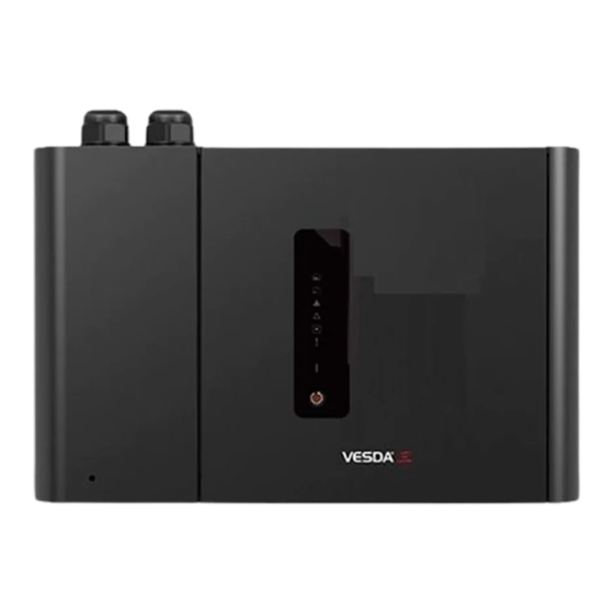
Status LEDs: Alert, Action, Fire 1, Fire 2, Disabled, Fault and Power. Controls: Reset and Disable button. 2.3.1 Status LEDS The VESDA-E VES-A00-P detector features a range of LED Indicators which illuminate when their respective activation conditions are met. Table 2-1: LED Indicators Symbol... -
Page 13: Internal Buttons
VESDA-E VES-A00-P Product Guide 2.3.2 RESET / DISABLE / ACKNOWLEDGE Button Figure 2-2: Reset / Disable / Acknowledge Button If there is an alarm or fault condition pressing the button the first time will acknowledge the condition. Subsequent presses will reset or disable the detector. -
Page 14: Vesdanet
VESDA-E VES-A00-P Product Guide Connection Usage? Initial Monitoring and Configuration Configuration Updates Use WiFi Use USB or Ethernet Figure 2-3: Connection Method The physical communication ports are located on the main board inside the detector. It is necessary to open the front door in order to access these ports. Refer to Section 7.2 for information on opening the front door. -
Page 15: Specifications
VESDA-E VES-A00-P Product Guide Specifications Table 2-2: VES-A00-P Detector Specifications Specification Value Supply Voltage 18 to 30 VDC (24 VDC Nominal) Power Consumption @24 VDC Aspirator Setting 1 Setting 5 Setting 10 Power (Quiescent) 7.9 W 9.7 W 14.8 W Power (In Alarm) 8.5 W... - Page 16 Two Fault Warning Levels Maintenance and Major Fault Maintenance Aids Filter and flow monitoring Event reporting via VESDAnet and event log Table 2-4: Ordering Information VESDA-E VES-A00-P Detector VES-A00-P Exhaust Adaptor US VSP-961 Note: Refer to Table 7-2 for the spare parts list.
-
Page 17: Dimensions
VESDA-E VES-A00-P Product Guide Dimensions inch 28.5 1.12 35.0 1.38 45.0 1.77 134.0 5.28 34.0 1.34 34.0 1.34 34.0 1.34 34.0 1.34 26.5 1.04 J 350.05 13.78 224.0 8.82 230.2 9.06 M 135.48 N 132.28 5.21 28.5 1.12 35.0 1.38 45.0 1.77... - Page 18 VESDA-E VES-A00-P Product Guide inch 17.5 0.69 315.0 12.4 17.5 0.69 D 144.99 5.71 77.2 3.04 Figure 2-5: Rear dimensions with Mounting Bracket www.xtralis.com...
- Page 19 VESDA-E VES-A00-P Product Guide inch 224.0 8.82 112.0 4.41 40.9 1.61 D 268.39 10.57 40.71 20.25 183.5 7.22 20.25 Figure 2-6: Rear Dimensions with hole locations for direct mounting www.xtralis.com...
- Page 20 VESDA-E VES-A00-P Product Guide This page is intentionally left blank. www.xtralis.com...
-
Page 21: Pipe Network Design And Installation
In this case the exhaust pipe needs to go back to the sampled area. Refer to Section 3.4. for further information. Refer to the VESDA Pipe Network Design Guide for best design practices. Installation Considerations The following points should be considered when installing sampling pipe: Minimize flexing in sampling pipes by supporting the pipe every 1.5m (5ft) or less, or at a distance... -
Page 22: Managing The Exhaust Air
VESDA-E VES-A00-P Product Guide screwdriver in the large slot and twist, or use a small screwdriver in the side slots to lever the plug out. Insert the pipes into the pipe inlet(s) ensuring a firm fit. Note: DO NOT glue the inlet pipes to the pipe inlet manifold. -
Page 23: Installation
VESDA-E VES-A00-P Product Guide Installation The VES-A00-P detector is shipped with the following components: 1 VESDA-E VES-A00-P detector Installation Sheet Mounting bracket Mounting template for directly mounting the detector to the mounting surface Exhaust Adaptor (US only) 1 End of Line resistor for the monitored GPI Check all components for damage and refer any concerns to your authorized representative. -
Page 24: Mounting
VESDA-E VES-A00-P Product Guide Mounting The VES-A00-P detector can be mounted in an upright or inverted position. Do not mount the detector with a sideways orientation as shown in Figure 4-3 below. Figure 4-3: Sideways orientation Ensure the mounting surface is flat as this allows an air tight seal to be achieved between the sampling pipe and the tapered air inlet pipes on the detector. - Page 25 VESDA-E VES-A00-P Product Guide 4.2.1 Inverting the Detector If the pipe network design requires that the sampling pipes enter the detector at the bottom, it is possible to achieve this by inverting the detector. In this case the fascia must be inverted on the detector so that the user interface has the correct orientation.
- Page 26 VESDA-E VES-A00-P Product Guide Legend A Top cover retaining tabs B Bottom cover retaining tabs Figure 4-6: Tabs used to remove top and bottom cover 4. Detach the tethers, Figure 4-7 and Figure 4-8. (You can leave the cables from the detector to the fascia connected.)
- Page 27 VESDA-E VES-A00-P Product Guide Figure 4-8: Detector with tethers detached 5. Detach the front door from the fascia by removing pin A from the hinge (Figure 4-9, Figure 4-10). Leave pin B in place – do not remove it. www.xtralis.com...
- Page 28 VESDA-E VES-A00-P Product Guide Figure 4-9: Removing door hinge pin A Figure 4-10: Detaching door www.xtralis.com...
- Page 29 VESDA-E VES-A00-P Product Guide 6. Change from setup A in Figure 4-11 to setup B by doing the following: a. Leave the fascia upright. b. Rotate the detector 180 degrees. c. Rotate the door 180 degrees and place it next to the right side of the fascia.
- Page 30 VESDA-E VES-A00-P Product Guide Figure 4-12: Replacing the door hinge pin - showing correct positioning of door and pin www.xtralis.com...
- Page 31 VESDA-E VES-A00-P Product Guide Figure 4-13: Replacing the door hinge pin Figure 4-14: Correct positioning of door hinge pin when fully in place 8. Re-attach the tethers. Attach at the slots circled in Figure 4-15. Position the tethers in the slots and pull up as shown in Figure 4-16.
- Page 32 VESDA-E VES-A00-P Product Guide Figure 4-16: Position the tethers and pull up to attach 9. Re attach the top and bottom covers. 10. Re-attach the fascia. Re-attach to the front of the detector by tightening the two retaining screws as shown in Figure 7-8.
- Page 33 VESDA-E VES-A00-P Product Guide 4.2.2 Mounting the Detector with the Mounting Bracket 1. Position the mounting bracket (A) to allow sampling pipes (B) and electrical conduit (C) to line up horizontally with the alignment marks (D) and vertically with the appropriate pipe depth line (Figure 4-17).
- Page 34 VESDA-E VES-A00-P Product Guide 5. Insert the remaining three mounting screws (B) and tighten them (Figure 4-20). Legend A Mounting bracket B Mounting screws Figure 4-20: Mounting Bracket 6. Align the mounting studs (A) on the rear of the detector with the mounting stud slots on the mounting bracket, and slide the detector down until the top of the detector is flush with the top of the mounting bracket (Figure 4-21).
- Page 35 VESDA-E VES-A00-P Product Guide 4.2.3 Mounting the Detector using the Mounting Template 1. Position the mounting template to allow sampling pipes (A) to horizontally line up with the alignment marks (B) and vertically align with the appropriate pipe depth line (Figure 4-23): 3/4 inch IPS pipe (1.05 inch OD) should vertically align with the top depth line (C).
- Page 36 VESDA-E VES-A00-P Product Guide Inverted Detector 3/4 ” IPS 25 mm tec to r of De Ed ge 25 mm 3/4 ” IPS Upright Detector Figure 4-25: Position conduit and pipes 8. Remove the mounting template. 9. In order to allow the detector to be positioned, retract the inlet and exhaust pipes and electrical conduit.
- Page 37 VESDA-E VES-A00-P Product Guide Upright Inverted Detector Detector Figure 4-28: Slide detector to the left Rotate the detector clockwise to position the large end of the detector’s top-left, or top-right for an inverted detector, keyhole over the head of screw B. Push the detector to the wall (Figure 4-29).
- Page 38 VESDA-E VES-A00-P Product Guide Upright Detector Inverted Detector Figure 4-31: Locking screw 13. Tighten the top and bottom screws. 14. Insert the pipes and electrical conduit. www.xtralis.com...
-
Page 39: Wiring
A00-P. 4.3.1 Cabling Inlets The VESDA-E VES-A00-P contains four inlets for power, relay and network cabling, located on the upper and lower sides of the detector base. The holes have a diameter of 26 mm (1.02 inch). Note: To maintain the specified IP rating, cable glands or conduit must be used. - Page 40 VESDA-E VES-A00-P Product Guide 4.3.2 Socket Locations Legend Power A Power Out B Power In VESDAnet C VESDAnet B D VESDAnet A Relays E 3 – Urgent Fault 1 – Disable G 2 – Minor Fault H 4 – Alert 5 – Action 7 –...
- Page 41 à la page 9. Power to Multiple Detectors Up to three VESDA-E VES detectors may be daisy chained to the same power supply by connecting the PWR OUT power passthrough socket to the PWR IN socket on each subsequent detector.
- Page 42 Figure 4-35: Example closed loop VESDAnet network The VESDA-E VES-A00-P detector is shipped with the VESDAnet A and B terminals looped. Remove the A and B links prior to connecting the detector to the VESDAnet. If the detector is not to be networked with other devices, then do not remove the A and B links.
- Page 43 VESDA-E VES-A00-P Product Guide 4.3.6 Relays The relays, located on the main processor card, interface to the Fire Alarm Control Panel (FACP) to communicate faults, alarms and disabled states. The relays can be programmed using Xtralis VSC. Relays 3 and 6 are permanently set for Urgent Fault and Fire 1 respectively. Table 4-22 below illustrates the default assignments of functions (conditions) to relays and summarizes the default behavior of each relay.
- Page 44 VESDA-E VES-A00-P Product Guide Table 4-2: Default Relay Assignments (continued...) Relay # Default Default to Description for default configuration Configurability Assignment Normally Energized Action Energizes when the Action alarm is Fully initiated. configurable Fire 1 Energizes when the Fire 1 alarm is initiated. Fire 1 cannot be removed.
- Page 45 VESDA-E VES-A00-P Product Guide 4.3.9 Typical Wiring to Fire Alarm Control Panel (FACP) The diagram below shows the correct way to wire VESDA-E detectors to a conventional fire alarm control panel (FACP). To next detector or End of Line resistor (EOL)
- Page 46 VESDA-E VES-A00-P Product Guide 4.3.11 Typical Wiring for Monitored GPI for PSU Monitoring The diagram below shows the correct way to configure power supply monitoring. It also shows where an End Of Line (EOL) resistor is correctly installed. Refer to Section 4.3.8 on page 38 for further information.
-
Page 47: Powering Up
VESDA-E VES-A00-P Product Guide Powering Up After installing the detector it is necessary to power up the system. The power up sequence lasts approximately 15 seconds. The VES-A00-P detector does not have a power switch i.e it is an "always on" device which is activated by applying powered cabling to the power input terminal on the main board (Figure 4-33). -
Page 48: Installation Checklist
VESDA-E VES-A00-P Product Guide Installation Checklist Site Name Address Detector Serial Number(s) and Date of Manufacture Name of Installer Signature Date Perform the following checks listed below to ensure that all the necessary items are completed before handing over to a commissioning engineer. -
Page 49: Preliminary System Check
VESDA-E VES-A00-P Product Guide Preliminary System Check A preliminary system check is required after installing the VES-A00-P detector, before it is commissioned for use. To perform the preliminary system check: Power up the detector by connecting the power supply to the Power In terminal. - Page 50 VESDA-E VES-A00-P Product Guide This page is intentionally left blank. www.xtralis.com...
-
Page 51: Configuration
A connection profile would need to be defined for the temporary USB connection, and then for the permanent connection using VESDAnet, Ethernet or WiFi. Note: Refer to the VESDA Communications Guide for further information. 5.1.1 Defining Connection Profiles in Xtralis VSC There are multiple ways to connect to a VES-A00-P detector. - Page 52 VESDA-E VES-A00-P Product Guide Figure 5-1: Connection Manager 2. Select Add. The Add Connection dialog is displayed (Figure 5-2). Figure 5-2: Add Connection 3. Select the VESDAnet connection option, then select Next. Adding a USB Connection 1. Select USB, then select Next (Figure 5-3). Figure 5-3: Select USB...
- Page 53 VESDA-E VES-A00-P Product Guide 2. Enter a unique name for the Connection or accept the pre-generated name, then select Finish (Figure 5-4). Figure 5-4: Enter a Connection Name Adding an Ethernet or WiFi connection 1. Select Ethernet / WiFi, then select Next (Figure 5-5).
- Page 54 VESDA-E VES-A00-P Product Guide Figure 5-6: Enter IP Address 3. Enter a unique name for the Connection or accept the pre-generated name, then select Finish (Figure 5-7). Figure 5-7: Enter a Connection Name www.xtralis.com...
-
Page 55: Connecting To The Detector
VESDA-E VES-A00-P Product Guide Connecting to the Detector Once a Connection Profile has been defined, it is possible to connect to the VES-A00-P detector using the following methods: 5.2.1 Connecting to a detector via USB Direct connection between the detector and the PC installed with Xtralis VSC can be made using a Type A to Type B USB interface lead. - Page 56 VESDA-E VES-A00-P Product Guide detector status screen. For static IP addresses, set Automatically obtain IP Address to off and set the IP Address, Subnet Mask and Default Gateway to a valid address in the building network. Set the detector authentication password. Refer to Section 5.3.1 on page 52 for further information.
- Page 57 5.2.4 Connection to a detector via VESDAnet A VES-A00-P that is part of a VESDAnet network can be accessed via another VESDA-E device acting as a gateway: the VES-A00-P must be physically connected to the VESDAnet, as described in Section 4.3.5.
-
Page 58: Authentication
VESDA-E VES-A00-P Product Guide Authentication The VES-A00-P has two levels of protection against unauthorized access. For connection via Ethernet or WiFi, a password of at least 8 characters must be used. After connection, a four digit PIN is used to control the access level. -
Page 59: Commands
VESDA-E VES-A00-P Product Guide Commands The following commands are able to be issued to the detector using buttons or the Xtralis VSC software. The following commands are able to be issued to the detector. As indicated below in Table 5-2, a small number of basic commands can be executed from the detector via buttons, while the full range of commands can be executed using the Xtralis VSC software. - Page 60 VESDA-E VES-A00-P Product Guide Table 5-2: Detector Commands (continued...) Command Description Execute From A button Xtralis VSC on the Software Detector Start AutoLearn Flow Starts the AutoLearn Flow process for the detector. The detector monitors the environment and determines appropriate airflow fault thresholds. The user is prompted to enter the monitoring period.
- Page 61 VESDA-E VES-A00-P Product Guide Table 5-2: Detector Commands (continued...) Command Description Execute From A button Xtralis VSC on the Software Detector Rebuild Zone List Re-learns the list of display modules that are assigned to the detector on the VESDAnet. Start Major Fault Test Generates a major fault on the detector and de- energizes the fault relay for 2 minutes.
-
Page 62: Configuration Options
Serial Number: The serial number of the device. This is factory set and cannot be changed. VESDA Zone: The unique zone number used to link this detector and remote display/relay devices or remote relay which output alarm and trouble status for this detector to the Fire Alarm Control Panel. - Page 63 VESDA-E VES-A00-P Product Guide 5.5.2 VESDAnet Options The VESDAnet options provide the ability to control network data transmission behaviour for VESDAnet connections. Note: Refer to Section 5.6 for the default settings. Figure 5-13: VESDAnet Communications Options The Communications configuration options are as follows: Preferred Port: The preferred VESDAnet port to be used to transmit network data from this device.
- Page 64 VESDA-E VES-A00-P Product Guide 5.5.3 Ethernet Options The Ethernet options provide the ability to configure the detector to join an existing wired Ethernet network using the normal building network connection process or be directly connected to a PC or laptop. Figure 5-14: Ethernet Options The Ethernet configuration options are as follows: Ethernet Enabled: Tick to enable Ethernet for use.
- Page 65 VESDA-E VES-A00-P Product Guide 5.5.4 WiFi Options The WiFi options provide the ability to configure the detector to join an existing WiFi network using the normal building network connection process. After the WiFi parameters have been entered and the user selects Apply or OK, the detector will connect to the access point and remain connected while the access point is available.
- Page 66 VESDA-E VES-A00-P Product Guide Static IP Address Configuration IP Address: IPV4 static address Subnet Mask: Subnet mask for static address Default Gateway: Gateway for static address 5.5.5 Security Options The Security options page allows you to define the number of WiFi/Ethernet connections and the USB, WiFi and Ethernet connection idle timeouts.
- Page 67 VESDA-E VES-A00-P Product Guide 5.5.6 Smoke Threshold Options The Smoke Threshold options provide the mechanism to set the smoke obscuration trigger point for each alarm level, and the ability to assign day or night thresholds to cater for different levels of activity in the protected area during these times.
- Page 68 VESDA-E VES-A00-P Product Guide Holidays: The settings used to define a holiday period. Use the dropdown calendars to choose the start and end times of the holiday (or break) period. Night time thresholds are used during the holiday period. 5.5.7 Airflow Options...
- Page 69 VESDA-E VES-A00-P Product Guide 5.5.8 Filter Option The Filter option page allows you to define the time period after which a filter fault will be generated. Figure 5-19: Filter Options Service Interval (days): The time period after a new filter is installed at which non urgent fault "Filter smoke- dust limit nearly exceeded "...
- Page 70 VESDA-E VES-A00-P Product Guide 5.5.9 Sector Names The Sector Names page allows the user to set the names of the sectors being monitored. Figure 5-20: Filter Options Sector Name – Sector Number 1 through 4: A description of the sector being monitored. This name will appear on Xtralis VSC and on the LCD display of the A10 model detector.
- Page 71 50% of the Fire 1 alarm threshold of the VES-A00-P. A single reference detector can be used by multiple VESDA detectors within the protected area. The percentage of reference smoke level subtracted can be set differently for each detector monitoring the protected area.
- Page 72 VESDA-E VES-A00-P Product Guide 5.5.11 General Purpose Inputs Options The General Purpose Inputs options page provides the ability to control the behavior of the Unmonitored and Monitored General Purpose Inputs (GPIs). The GPIs can be configured to initiate a number of different actions.
- Page 73 VESDA-E VES-A00-P Product Guide Table 5-3: GPI Operation (continued...) Function State Change Fault 761 Mains OK Unmonitored GPI The detector reports “Power Supply AC Input Failure” (fault 761) when ≤ 2 VDC. The detector does not report “Power Supply AC Input Failure” (fault 761) when ≥...
- Page 74 VESDA-E VES-A00-P Product Guide Table 5-3: GPI Operation (continued...) Function State Change Use Night-time Unmonitored GPI Threshold The detector uses night-time Day or Night Night Day or Night thresholds while ≥ 5 VDC. Monitored GPI Closed The detector uses night-time thresholds while the contact is...
- Page 75 VESDA-E VES-A00-P Product Guide 5.5.12 Relay Options The Relay options page provides the ability to determine which alarm or fault condition is assigned to each relay and whether each condition is latched. In addition, each relay can be configured Normally Energized or Normally De-Energized.
- Page 76 VESDA-E VES-A00-P Product Guide Normally Energized: The Normally Energized or Normally De-Energized setting of each relay can be configured using the checkbox in the Normally Energized row: If checked the relay is set Normally Energized. If unchecked the relay is set Normally De-energized.
-
Page 77: Factory Default Settings
VESDA-E VES-A00-P Product Guide Factory Default Settings Table 5-4: Default Settings Parameter Default Values Range Affected by Return to Factory Defaults Minimum Maximum command General Network name Blank Location Blank Address (VESDA zone) Detector Password None VESDAnet Preferred port Port A Port A... - Page 78 VESDA-E VES-A00-P Product Guide Table 5-4: Default Settings (continued...) Parameter Default Values Range Affected by Return to Factory Defaults Minimum Maximum command Ethernet /WiFi No timeout 15 minutes 24 hours connection idle timeout (hours) Smoke Thresholds (See recommendation for lowest Alert in Section 6.)
- Page 79 VESDA-E VES-A00-P Product Guide Table 5-4: Default Settings (continued...) Parameter Default Values Range Affected by Return to Factory Defaults Minimum Maximum command Air Flow - Valve Test Do every 7 day Do every day Do every 7 Pipes in Use All pipes in use...
- Page 80 VESDA-E VES-A00-P Product Guide This page is intentionally left blank. www.xtralis.com...
-
Page 81: Commissioning
VESDA-E VES-A00-P Product Guide Commissioning The VES-A00-P has been designed to simplify commissioning processes. The AutoLearn function allows the unit to assess its environment and setup appropriate alarm and flow thresholds. The detector is programmed using the Xtralis VSC software. Once the VES-A00-P detector has been commissioned, it will report alarms and faults according to the parameters defined during installation. -
Page 82: Autolearn Smoke
VESDA-E VES-A00-P Product Guide 0.08 %/ft = 0.04 %/ft Example 2: Fire 1 Pipe 1 0.3 %/m (0.1%/ft) Pipe 2 0.25%/m (0.08%/ft) Pipe 3 0.4%/m (0.12%/ft) Pipe 4 0.2%/m (0.06%/ft) Set the lowest alert threshold to no higher than lowest Fire 1/ #pipes in use. -
Page 83: Autolearn Flow
Results are logged and compared to subsequent tests to note variations of the system. Refer to the VESDA Commissioning Guide (document # 10195) for details of the commissioning smoke test. www.xtralis.com... - Page 84 VESDA-E VES-A00-P Product Guide This page is intentionally left blank. www.xtralis.com...
-
Page 85: Maintenance
VESDA-E VES-A00-P Product Guide Maintenance To maintain the VES-A00-P detector at its peak performance level, the recommended maintenance schedule shown in Table 7-1 below should be followed. Table 7-1: Recommended maintenance schedule for the VES-A00-P detector Maintenance Check Quarterly Six Monthly Annual Biennial Power Supply and Battery... -
Page 86: Open The Door
VESDA-E VES-A00-P Product Guide Open the Door Several maintenance functions require that front door be opened. Open the Front Door 1. Open the door by inserting a thin screwdriver into hole (B) and pushing firmly. Figure 7-1: Open the door www.xtralis.com... -
Page 87: Replacing The Filter
VESDA-E VES-A00-P Product Guide Replacing the Filter To maintain the operational integrity of the detector, it is recommended that the Filter be replaced every two years, or when a filter fault occurs. It may be necessary to replace the filter more often where the detector is installed in environments that experience high levels of contamination. - Page 88 VESDA-E VES-A00-P Product Guide 3. Tilt the filter towards the left-hand side of the detector (Figure 7-3). The filter has hinge pins at its base which allow it to be tilted on the chamber manifold. Figure 7-3: Tilt Filter towards the left-hand side of the detector 4.
- Page 89 VESDA-E VES-A00-P Product Guide Figure 7-5: Engage hinge pins 3. Tilt the filter to the right. 4. Firmly press, as shown in Figure 7-6, until the filter makes a distinct clicking sound and no additional movement is possible. Figure 7-6: Reinstall the Filter www.xtralis.com...
-
Page 90: Remove The Fascia
VESDA-E VES-A00-P Product Guide Remove the Fascia Several maintenance functions require that the fascia be removed from the VES-A00-P detector in order to perform them. Caution: Electrostatic discharge (ESD) precautions need to be taken prior to removing the fascia from the detector. A wrist strap must be connected to the case of the detector (Figure 7-7). - Page 91 VESDA-E VES-A00-P Product Guide Figure 7-8: Fascia removal - remove screws 3. Remove the fascia and allow it to hang by the two tether straps. Figure 7-9: Fascia hanging on two tethers www.xtralis.com...
-
Page 92: Replacing The Aspirator
VESDA-E VES-A00-P Product Guide Replacing the Aspirator Caution: Electrostatic discharge (ESD) precautions need to be taken prior to removing the fascia from the detector. A wrist strap must be connected to the case of the detector (Figure 7-7). Attention : Les precausions contre le decharge electrostatique dois etre respecter avant d’ouvrir le panneau du detecteur. - Page 93 VESDA-E VES-A00-P Product Guide Figure 7-12: Remove aspirator from the detector Reinstall the replacement Aspirator To replace the aspirator, follow the removal procedure in reverse. www.xtralis.com...
-
Page 94: Replacing The Smoke Detection Chamber
VESDA-E VES-A00-P Product Guide Replacing the Smoke Detection Chamber Caution: Electrostatic discharge (ESD) precautions need to be taken prior to removing the fascia from the detector. A wrist strap must be connected to the case of the detector (Figure 7-7). Attention : Les precausions contre le decharge electrostatique dois etre respecter avant d’ouvrir le panneau... - Page 95 VESDA-E VES-A00-P Product Guide Figure 7-13: Undo Chamber retaining screws 4. Disconnect the chamber loom from the connector labeled J3 (Figure 7-14). www.xtralis.com...
- Page 96 VESDA-E VES-A00-P Product Guide Figure 7-14: Disconnect Chamber Loom 5. Remove the chamber from the detector base (Figure 7-15). Figure 7-15: Remove the Chamber from the detector base www.xtralis.com...
- Page 97 VESDA-E VES-A00-P Product Guide Installing the replacement Smoke Detector Chamber 1. Position the two indicated looms as shown in Figure 7-16. Position the indicated loom sections beside the air flow sensing module, not on top of it. This will ensure that, when installing the chamber, the looms are not caught between the chamber and the air flow sensing module.
- Page 98 VESDA-E VES-A00-P Product Guide 3. Re-install the chamber as shown in Figure 7-18. Be careful to hold looms (A) and (B) in the position shown so that the looms are not caught between the chamber and other parts of the detector. Figure 7-18: Install the Chamber 4.
-
Page 99: Replacing The Sampling Module
VESDA-E VES-A00-P Product Guide Replacing the Sampling Module Caution: Electrostatic discharge (ESD) precautions need to be taken prior to removing the fascia from the detector. A wrist strap must be connected to the case of the detector (Figure 7-7). Attention : Les precausions contre le decharge electrostatique dois etre respecter avant d’ouvrir le panneau du detecteur. - Page 100 VESDA-E VES-A00-P Product Guide 4. Press on the lever on the connector to release the catch (Figure 7-20). Figure 7-20: Release the Sampling Module cable 5. Undo the three screws holding the Sampling Module (Figure 7-21). www.xtralis.com...
- Page 101 VESDA-E VES-A00-P Product Guide Figure 7-21: Undo Sampling Module screws www.xtralis.com...
- Page 102 VESDA-E VES-A00-P Product Guide 6. Remove the Sampling Module. Be sure to include the rubber seal on the base of the Sampling Module (Figure 7-22). Figure 7-22: Remove Sampling Module Installing a replacement Sampling Module 1. Firmly press the Sampling Module into the detector in the direction of the arrow shown so that the rubber seal on the Sampling Module is seated on the pipes in the detector (Figure 7-23).
- Page 103 VESDA-E VES-A00-P Product Guide Figure 7-23: Reinstall Sampling Module 2. Tighten the three screws and re-connect the Sampling Module cable (Figure 7-19). www.xtralis.com...
-
Page 104: Replacing The Ultrasonics Flow Sensing And Scanning Module
VESDA-E VES-A00-P Product Guide Replacing the Ultrasonics Flow Sensing and Scanning Module Caution: Electrostatic discharge (ESD) precautions need to be taken prior to removing the fascia from the detector. A wrist strap must be connected to the case of the detector (Figure 7-7). - Page 105 VESDA-E VES-A00-P Product Guide Figure 7-25: Remove the three screws holding the Ultrasonics Flow Sensing and Scanning Module 4. Remove the Ultrasonics Flow Sensing and Scanning Module from the detector base. (Figure 7-26) Figure 7-26: Remove the Ultrasonics Flow Sensing and Scanning Module Installing the replacement Ultrasonics Flow Sensing and Scanning Module 1.
- Page 106 VESDA-E VES-A00-P Product Guide www.xtralis.com...
-
Page 107: Spare Parts
VESDA-E Exhaust Adaptor US VSP-962 VESDA-E Filter VSP-962-20 VESDA-E Filter - 20 Pieces VSP-963 VESDA-E Aspirator VSP-964-03 VESDA-E Smoke Detection Chamber VSP-965 VESDA-E Sampling Module VSP-968 VESDA-E VES-A00-P Front Cover Plastic (LEDs) VSP-969-S VESDA-E VES-A10-P Front Cover Plastic (3.5” Display) www.xtralis.com... - Page 108 VESDA-E VES-A00-P Product Guide This page is intentionally left blank. www.xtralis.com...
-
Page 109: Troubleshooting
Fault Reporting through Relays VESDA-E devices are often interfaced with Fire Alarm Control Panels (FACPs) or building management systems (BMS) via relays. In such instances the fault relays signal a fault condition to the FACP or the BMS. - Page 110 VESDA-E VES-A00-P Product Guide This page is intentionally left blank. www.xtralis.com...
-
Page 111: Product Security Advice
IT infrastructure. VESDA devices including HLIs must not be accessible from the Internet. Any provision of remote access to VESDA devices must be subjected to a full cyber security risk assessment and regular review. WPA-2 encryption must be used whenever Wi-Fi is enabled. - Page 112 VESDA-E VES-A00-P Product Guide This page is intentionally left blank. www.xtralis.com...
-
Page 113: A Commissioning Forms
VESDA-E VES-A00-P Product Guide A Commissioning Forms This is the main commissioning form for each customer site. Table A-1: VESDA-E commissioning form Customer Name Site Address Installer (Name & Contact) Commissioner (Name & Contact) Commissioning Checks Done (Y/N) Notes Aspirator speed setting and pipes in use configured as per ASPIRE. - Page 114 VESDA-E VES-A00-P Product Guide Fire 2 Fire 1 Action Alert First Alarm Sector 2: Fire 2 Fire 1 Action Alert First Alarm Sector 3: Fire 2 Fire 1 Action Alert First Alarm Sector 4: Fire 2 Fire 1 Action Alert First Alarm Urgent Fault relay connection to fire panel tested (using the Xtralis VSC Urgent Fault Test command).
- Page 115 VESDA-E VES-A00-P Product Guide Commissioning checklist for the Remote Display/Relay – If used. Commissioning Checks Done (Y/N) Notes Zone number configured. Have checked that no faults are reported. The alarm and fault relay outputs are wired to the fire panel. Test the Remote Display/Relay’s Relay output connections to the fire panel using the Xtralis VSC Relay Test command.
- Page 116 VESDA-E VES-A00-P Product Guide Sector 4: Fire 2 Fire 1 Action Alert First Alarm Fire 1 relay connection from Remote Display/Relay to fire panel tested (using the Xtralis VSC Alarm Test Command for the detector). Urgent Fault relay connection from Remote Display/Relay to fire panel tested (using the Xtralis VSC Alarm Test Command for the detector).
- Page 117 VESDA-E VES-A00-P Product Guide VES-A00-P Detector Commissioning Configuration To record the detector's configuration you can print it using Xtralis VSC. To print the configuration select the detector on the Xtralis VSC tree view at left and choose the Print command on the File menu.
- Page 118 VESDA-E VES-A00-P Product Guide This page is intentionally left blank. www.xtralis.com...
- Page 119 H High Airflow Environment Where there are 10 or more air exchanges per hour. High Level Interface (HLI) A communications interface between a VESDA device and other pieces of equipment using another communications protocol. L Latching If the cause of a condition is removed (for example, smoke decreases below the threshold) and latching is enabled, the detector “remembers”...
- Page 120 This is the primary method used to signal alarms and faults. S Sampling Network The pipe network constructed to allow the VESDA-E detector to draw air for sampling. Sensitivity Sensitivity refers to sensitivity to smoke. A high sensitivity denotes response to a lower concentration of smoke than a low sensitivity.
- Page 121 VESDA-E VES-A00-P Product Guide Index reset return to factory defaults access level set system date and time 52, 71 standby 52, 71 start air flow fault test start alarm test accessories start AutoLearn flow display module 8, 37-38 start AutoLearn smoke...
- Page 122 VESDA-E VES-A00-P Product Guide event log 3, 10, 52, 61-62, 71, 113 exhaust 5, 9, 15-18, 29, 41-43 maintenance check pipe flow check pipe network FACP 37, 39, 103, 113 clean sampling point fault 3, 5-8, 10, 34, 37, 39, 41, 55, 62, 66,...
- Page 123 VESDA-E VES-A00-P Product Guide mounting 18, 27, 29 network 9, 15, 113 sampling module 5, 93, 101 network design 15-16 sensitivity 3, 9, 113 network testing settings size default pipe flow rate 15, 75 significant smoke change pipe length specifications pipe network...
- Page 124 VESDA-E VES-A00-P Product Guide zone 55-56, 79, 113 www.xtralis.com...
Need help?
Do you have a question about the VESDA-E VES-A00-P and is the answer not in the manual?
Questions and answers