Table of Contents
Advertisement
Advertisement
Table of Contents

Subscribe to Our Youtube Channel
Related Manuals for VESDA VLP


Summary of Contents for VESDA VLP
- Page 1 VESDA VLP Product Guide September 2014 Document: 10278_09 Part Number: 19145...
- Page 3 VESDA by Xtralis VESDA VLP Product Guide Intellectual Property and Copyright This document includes registered and unregistered trademarks. All trademarks displayed are the trademarks of their respective owners. Your use of this document does not constitute or create a licence or any other right to use the name and/or trademark and/or label.
- Page 4 You will also find instructions on installing, cabling and powering up the detector. This guide is for anyone involved with the design, maintenance and purchasing of the VESDA system. It is assumed that anyone using this manual has knowledge and the appropriate certification from the local fire and electrical authorities.
- Page 5 Relays used on the detector are marked “TX2-5V”, “G6S-2-5V” or “EC2-5NU”. VESDA detectors must not be connected or disconnected to a PC while the equipment is powered in an FM Division 2 hazardous (classified) location (defined by FM 3611).
- Page 6 Through validation testing, Underwriters Laboratories Inc. has verified that VESDA ECO gas detectors, when installed within the sample pipe network, present no significant effects on the smoke detection performance of VESDA. The use of the ASPIRE2 calculation software is required to verify system design performance with all devices included in the design.
-
Page 7: Table Of Contents
Mounting the VESDA VLP Securing the mounting bracket Mounting the VESDA VLP in Normal Orientation Mounting the VESDA VLP in the Inverted Orientation Mounting the VESDA VLP without a mounting bracket Recess mounting kit Connecting the VESDA VLP to the Pipe Network... - Page 8 VESDA VLP Product Guide VESDA by Xtralis This page is intentionally left blank. www.xtralis.com...
-
Page 9: Introduction
VESDA VLP Product Guide Introduction The VESDA VLP is an aspirating smoke detector providing very early warning of fire conditions by drawing air samples through an air sampling pipe network. The detector chamber can detect presence of smoke at very low concentrations. The embedded and PC software complimenting the VESDA VLP provides a wide range of user defined parameters and reporting capabilities. - Page 10 VESDA VLP Product Guide VESDA by Xtralis This page is intentionally left blank. www.xtralis.com...
-
Page 11: Operation
Operation An air sampling pipe network collects air samples from a protected area. The integrated aspirator draws air into the sampling pipes through a pipe inlet manifold. Up to four pipes can be connected to a VESDA VLP detector. Inside the VESDA VLP, a sample of air is passed into the laser detection chamber. Ultra-fine air filtration provides very clean air to protect the optical surfaces inside the detector from contamination. -
Page 12: Vesda Vlp Configurations
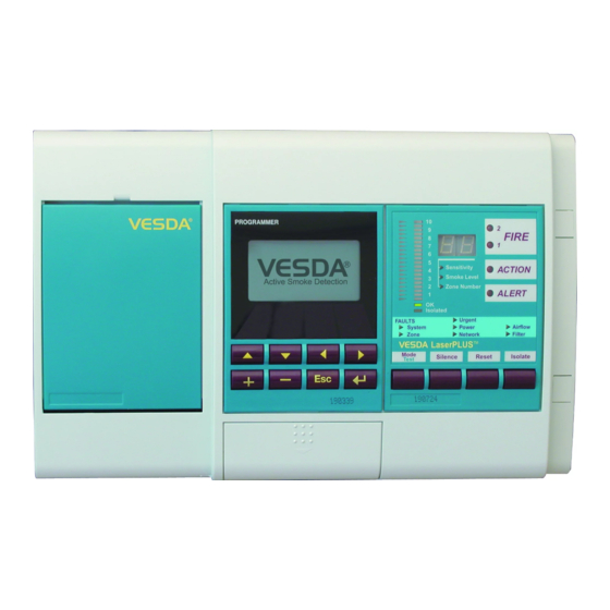
Display Module The VESDA VLP Display Module is mounted either on the detector front cover or at a remote location in a remote mounting box or a 19” subrack. It provides a visual representation of the smoke levels and the four alarm stages for the assigned detector. - Page 13 URGENT: A serious fault requiring immediate attention SYSTEM: A fault affecting the network to which the Display Module is connected ZONE: A fault in the VESDA Zone monitored by the Display Module POWER: A fault in the power supply if the GPI function is used...
- Page 14 Sensitivity: Shows the level of smoke that must be measured to illuminate the entire bar graph and always corresponds with the Fire 1 alarm level. Smoke Level: Indicates the current level of smoke in the relevant VESDA Zone and is represented as % obs/m or % obs/ft.
-
Page 15: Components
VESDA by Xtralis VESDA VLP Product Guide Components Legend A Front cover Pipe inlet manifold B Termination card Air filter C Blank card protecting processor card G Aspirator D Chassis with laser detector chamber H Mounting box/enclosure Figure 2-5: An exploded view of the detector... - Page 16 VESDA VLP Product Guide VESDA by Xtralis This page is intentionally left blank. www.xtralis.com...
-
Page 17: Product Information
4.0 kg (9 lbs) including Display and Programmer Modules Operating Conditions Temperature: To operate the VESDA VLP detector outside these Detector Ambient: 0°C–39°C (32°–103°F) parameters please contact your nearest VESDA Technical Sampled Air: -20° - 60°C (-4° - 140°F) Office. - Page 18 OFF the UL listing will be voided. Notes: For operating the VESDA VLP Detector outside the parameters mentioned above please contact VESDA Technical Support UL Mode: Factory Default = ON (Fire 2 set to 12% obs/m 4% obs/ft. to comply with UL268) Factory Default = OFF (Fire 2 Threshold can be set up to 20% obs/m 6.25%/ft)
-
Page 19: Dimensions
VESDA by Xtralis VESDA VLP Product Guide Dimensions Figure 3-1: Dimensions (rear view) Figure 3-2: Dimensions www.xtralis.com... -
Page 20: Default Settings
VESDA VLP Product Guide VESDA by Xtralis 3.2.1 Default Settings Table 3-2: Factory default settings and permissible thresholds Parameter Default Values Range Access Level Minimum Maximum Event Log - Events Smoke Level Enabled Alarms Enabled Faults Enabled User Action Enabled Fire 2 Threshold 2% obs/m 0.02% obs/m... - Page 21 VESDA by Xtralis VESDA VLP Product Guide Table 3-2: Factory default settings and permissible thresholds (continued...) Parameter Default Values Range Access Level Minimum Maximum Filter Service Interval 731 days (2 years) 1 Day 3655 days (10 years) Adm Reference detector: Reference Zone...
-
Page 22: Relays
VESDA VLP Product Guide VESDA by Xtralis Relays The relays on the head termination card interface to Fire Alarm Control Panels to communicate faults, alarms and isolate states. The relays can be programmed using PC based software or the LCD Programmer and can be assigned multiple assignments. - Page 23 The GPI can be configured to initiate a number of different actions - including, by default, a Remote Reset function. The GPI can be configured through the ‘Miscellaneous’ screen menu of the LCD programmer. Refer to the VESDA LCD Programmer Product Guide for details. Table 3-5: GPI Functions...
- Page 24 VESDA VLP Product Guide VESDA by Xtralis This page is intentionally left blank. www.xtralis.com...
-
Page 25: Mounting The Vesda Vlp
Mounting the VESDA VLP The VESDA VLP detector can be mounted onto the wall or on any suitable secure surface using the mounting bracket. It is strongly recommended that the detector is mounted on to the mounting bracket included with the packaging. -
Page 26: Mounting The Vesda Vlp In The Inverted Orientation
If the detector is fitted with a LCD Programmer and/or a Display Module, re-orient these to the upright position. Mount the detector in inverted orientation onto the mounting bracket. Figure 4-3: Mounting the VESDA VLP detector in inverted orientation onto the mounting bracket Mounting the VESDA VLP without a mounting bracket In the event the detector has to be mounted directly onto the mounting surface, remove the chassis from the mounting box. -
Page 27: Recess Mounting Kit
VESDA by Xtralis VESDA VLP Product Guide Recess mounting kit These kits are used to house a detector inside a wall cavity. Figure 4-4: Recess mounting kit www.xtralis.com... - Page 28 VESDA VLP Product Guide VESDA by Xtralis This page is intentionally left blank. www.xtralis.com...
-
Page 29: Connecting The Vesda Vlp To The Pipe Network
VESDA by Xtralis VESDA VLP Product Guide Connecting the VESDA VLP to the Pipe Network Inlet Pipes The inlets in the pipe inlet manifold are designed to receive a standard pipe of 25 mm (1 in) OD. A 25 mm to 1.050 inches adaptor to fit the pipe inlet manifold is included for all shipments to USA. -
Page 30: Managing The Exhaust Air
VESDA VLP Product Guide VESDA by Xtralis Managing the Exhaust Air To exhaust air from the detector, use the exhaust ports at the rear or at the bottom of the head mounting box. Remove the appropriate exhaust port plugs and if required, connect an outlet pipe to the exhaust manifold. In the event the side port is used as an exhaust port, press out the knockout hole. -
Page 31: Wiring Connections
RS 485 (Belden 9841 - 120 Ohm) twisted pair cables, or similar cables be used. The VESDA VLP detector is shipped with the VESDAnet A and B terminals looped. If the detector is not to be networked with other devices, then do not disturb this loop. Remove this loop to connect the detector to the VESDAnet. - Page 32 VESDA VLP Product Guide VESDA by Xtralis Shield Shield Shield Shield Shield Shield Module 1 Module 2 Module 3 Shield Shield Shield Shield Module 5 Module 4 Figure 6-3: An example of the wire connection for VESDAnet (closed loop for illustrative purposes only) 6.1.2...
- Page 33 Typical Wiring To Fire Alarm Control Panel (FACP) The diagram below shows the correct way to wire VESDA laser detectors to a conventional fire alarm control panel (FACP). It also shows where an End Of Line (EOL) resistor is correctly installed.
- Page 34 VESDA VLP Product Guide VESDA by Xtralis This page is intentionally left blank. www.xtralis.com...
-
Page 35: Power Source
For further information, refer to Section 3.1 on page 11. Caution: The VESDA VLP detector will not operate when the supply is reversed. Attention : Le détecteur VESDA VLP ne fonctionnera pas avec une alimentation inversée. - Page 36 VESDA VLP Product Guide VESDA by Xtralis This page is intentionally left blank. www.xtralis.com...
-
Page 37: Backup Battery
Backup Battery The power supply for the VESDA VLP detector is switched to a back up battery in the event of a mains power supply disruption. The size of the back up battery is determined by local standards and codes, the total power required by the system, back up time required, allowance for reduction in capacity with age and expected temperature variations. - Page 38 VESDA VLP Product Guide VESDA by Xtralis This page is intentionally left blank. www.xtralis.com...
-
Page 39: Powering Up
Powering Up A VESDA VLP detector must be powered up by VESDA accredited personnel only. After installing the VESDA VLP detector it is necessary to power up the system. The system takes approximately 15 seconds to power up. If the system fails to power up, check all power wires are secured to its terminals and the polarities of the power wires are correctly terminated. -
Page 40: Installation Checklist
VESDA VLP Product Guide VESDA by Xtralis Installation Checklist Site Name Address Detector Serial Number(s) and Date of Manufacture Name of Installer Signature Date Perform the following checks listed below to ensure that all the necessary items are completed before handing over to a commissioning engineer. -
Page 41: Preliminary Systems Check
VESDA VLP Product Guide 10 Preliminary Systems Check A preliminary systems check is required after installing the VESDA VLP detector, before it is commissioned for use. The check can be conducted by connecting the detector to a LCD Programmer or using Xtralis VSC PC based software. - Page 42 VESDA VLP Product Guide VESDA by Xtralis This page is intentionally left blank. www.xtralis.com...
-
Page 43: Maintenance
Maintenance can be conducted by the original installer, VESDA distributor, or a service contractor. To work effectively the VESDA VLP detector needs to be supported by a well designed pipe network. The VESDA Maintenance Guide contains a schedule for pipe network maintenance. - Page 44 VESDA VLP Product Guide VESDA by Xtralis Legend A Cover plate screws B Screw covers Figure 11-1: Removing front cover 5. Disconnect data cables connecting the chassis assembly to the termination card, front panel modules (if fitted) and manifold. Legend C Termination cable...
- Page 45 Separating the set and replacing it with components from another VESDA VLP will cause the detector to malfunction. This will require the chassis to be returned to the factory.
-
Page 46: Internal Wiring
VESDA VLP Product Guide VESDA by Xtralis 11.2 Internal Wiring The table below provides the cable loom interconnecting details inside the detector. Use the look up table in conjunction with the attached circuit diagram to assist with maintenance. Table 11-2: Interconnecting loom details... - Page 47 VESDA by Xtralis VESDA VLP Product Guide Legend A Detector Chamber B Programmer Module C Display Module D Termination Card Processor Card Aspirator G Flow Sensor Card Figure 11-5: Internal wiring diagram www.xtralis.com...
-
Page 48: Spare Parts
Blank Plate, non-EMC painted, with Logo VSP-001 LCD Programmer VSP-002 Display Module VSP-005 Filter Cartridge VSP-006 VESDA VLP Detector Chassis assembly complete with manifold VSP-011 Recess Mounting Kit for VESDA VLP VSP-013 Detector Cover Assembly complete with EMC Shields VSP-014... -
Page 49: Index
VESDA by Xtralis VESDA VLP Product Guide Index 19" subrack cable entry cables 11, 25, 37 calibration access level 14-15 capacity action 5, 7 alarm air inlets standby air sampling 3, 5, 34 total airflow 3, 5, 35 chamber 3, 5, 9, 20, 37, 40... - Page 50 VESDA VLP Product Guide VESDA by Xtralis filter cover filter service interval 14-15 mains ok filter switch card mains power filtering 5, 12 maintenance ii, 8, 12, 37 fire 3, 6-7 maintenance frequency Fire Panel 27, 37 maximum 14-15 fire1 minimum 14-15...
- Page 51 VESDA by Xtralis VESDA VLP Product Guide relay 16, 25 thresholds 3, 7, 11, 14-15, 17, 33 action action 14-15 alert alert 14-15 fire 1 fire 1 14-15 fire 2 fire 2 14-15 isolate minor fault UL version 14-15 urgent fault user action...
-
Page 52: Www.xtralis.com
VESDA VLP Product Guide VESDA by Xtralis This page is intentionally left blank. www.xtralis.com...
Need help?
Do you have a question about the VLP and is the answer not in the manual?
Questions and answers