VESDA lasercompact VLC-500 Product Manual
Hide thumbs
Also See for lasercompact VLC-500:
- Installation instructions (2 pages) ,
- Installation manual (32 pages)

Related Manuals for VESDA lasercompact VLC-500


Summary of Contents for VESDA lasercompact VLC-500
- Page 1 ® A LaserCOMPACT ™ PRODUCT MANUAL VLC-500 (Relays Only) Model VLC-505 (VESDAnet) Model March 2000 Version 1.0...
- Page 2 Publication history Release 1.0 February 2000 Copyright Information ©2000 Vision Systems – VESDA™. All Rights Reserved. VESDA is a registered trademark of Vision Products Pty Ltd. VESDA LaserPLUS, LaserSCANNER, LaserCOMPACT, AutoLearn, InfoWORKS, ASPIRE, VSM, VESDAnet and VESDAlink are trademarks of Vision Products Pty Ltd.
-
Page 3: Table Of Contents
Contents Overview ......................... 2 Product Description....................... 3 Front View of LaserCOMPACT..................3 Product Model, Approvals and Standards Label.............. 3 Operation ......................... 4 2.3.1 LED and Reset/Isolate Push Button Switch Functions ..........4 Factory Default Settings....................5 2.4.1 Factory Default User Levels ..................5 2.4.2 Factory Default PIN Numbers .................. -
Page 4: Overview
Modelling program results. VESDA products are only distributed through trained and accredited channels. It is understood that personnel installing this equipment are familiar with the VESDA technology and have a good understanding of local codes and standards regarding electrical cabling. -
Page 5: Product Description
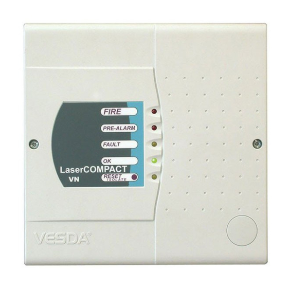
VESDA ® LaserCOMPACT Product Manual 2. Product Description 2.1 Front View of LaserCOMPACT Figure 1 Front View of LaserCOMPACT Model 2.2 Product Model, Approvals and Standards Label A label similar to that shown in Figure 2 is located at the bottom of the LaserCOMPACT enclosure and displays the detector model, approvals and standards. -
Page 6: Operation
VESDA ® LaserCOMPACT Product Manual 2.3 Operation 2.3.1 LED and Reset/Isolate Push Button Switch Functions Refer to Figure 5 for the location of the LED indicators. The functions of the LED indicators on the front panel from top to bottom and the push button Reset/Isolate switch are:- This RED LED lights up when the Fire alarm threshold is initiated. -
Page 7: Factory Default Settings
Up to 10 Users and 4 Administrators may be added. 2.4.2 Factory Default PIN Numbers The factory default Personal Identification Numbers (PIN) are distributed to authorised personnel attending accredited VESDA training courses and may be altered after gaining access into the system. 2.5 LaserCOMPACT Detector Models The LaserCOMPACT comes in two models and are as follows:- 2.5.1 Relays Only (RO) Model (Part No. -
Page 8: Detector Mounting
VESDA ® LaserCOMPACT Product Manual 2.6 Detector Mounting The LaserCOMPACT comes with a separate metal mounting bracket that is attached onto the mounting location. The detector can only be mounted with the supplied mounting bracket. The back of the detector is slotted over the four tabs on the mounting bracket and is locked in place with an anti-tamper screw located inside the enclosure. -
Page 9: Auxiliary Terminals
VESDA ® LaserCOMPACT Product Manual 2.8 Auxiliary Terminals The auxiliary terminals on the termination card are Bias, Reset and LED. Refer to Section 4.7 for wire connection details. These terminals have the following functions:- Bias terminals These output terminals provide 10VDC supply to power the Reset input terminals via a remote ON/OFF switch. -
Page 10: Assembly Description
VESDA ® LaserCOMPACT Product Manual 3. Assembly Description 3.1 Assembly Description The components of the LaserCOMPACT are housed inside a grey plastic enclosure with a decal fascia on the front cover and a metal back panel. The front cover is removable and is secured to the enclosure with two screws located on the left and right hand side of the cover. - Page 11 VESDA ® LaserCOMPACT Product Manual LED Indicators Reset/Isolate Push Button Switch Figure 5 Front View of LaserCOMPACT Air Inlet Port Cable Entry Ports Wire Terminal Strips Programming Socket 15 pin for VN model 9 pin for RO model Termination Card Anti Tamper Screw Fuse 1.5A...
-
Page 12: Front Cover And Leds
VESDA ® LaserCOMPACT Product Manual 3.2 Front Cover and LEDs The front cover has a self adhesive printed decal attached next to the LED display. On the rear of the cover is a card with LEDs and a Reset switch. This card connects to the termination card with a wire loom labelled LED CARD. -
Page 13: Aspirator
VESDA ® LaserCOMPACT Product Manual 3.7 Aspirator The aspirator is a proprietary high efficiency suction air pump that draws in air through a network of sampling air pipes and passes a small sample of the filtered air into the laser detection chamber. -
Page 14: Termination Card Details
VESDA ® LaserCOMPACT Product Manual 4. Termination Card Details 4.1 Wire Terminal Location for RO Model Pin 1 Terminal A Terminal B Pin 1 FIRE (NO) Bias (-) (GND) FIRE (C) Reset (-) PRE-ALARM (NO) Reset (+) PRE-ALARM (C) Bias (+) -
Page 15: Power Terminals
VESDA ® LaserCOMPACT Product Manual 4.3 Power Terminals There are four power terminals designated Power (+) and Power (-) on Terminal B for 24VDC power connection. The Power (+) terminal is for positive 24VDC supply and the Power (-) terminal is for DC Ground. The four power terminals enable power to be brought into the detector via a single wire pair and looped out to another device via another wire pair. -
Page 16: Relay Terminals
VESDA ® LaserCOMPACT Product Manual Detector 1 Detector 2 Detector 3 Terminal B Terminal B Terminal B Shield Shield Shield Shield Shield Shield Shield Shield Shield Shield Detector 5 Detector 4 Terminal B Terminal B Figure 10 Wire Connection Details (Closed Loop) for VESDAnet Terminals... -
Page 17: Programming Socket
Use a LCD Programmer and connect the programmer cable to the 15 pin VESDAnet programming socket. Use a PC with a VESDA PC-Link HLI device and the appropriate data cables to connect to the 15 pin VESDAnet programming socket. 4.7 Auxiliary Terminals... -
Page 18: Reset Terminals (General Purpose Input)
VESDA ® LaserCOMPACT Product Manual 4.7.2 Reset Terminals (General Purpose Input) This input terminal pair could be used for one of the three functions listed below. • Reset/Isolate Switch • Mains OK • Standby This input terminal requires a voltage supply between 5V to 33V DC to operate. Connect the RESET (+) to the positive output and the RESET (-) to the ground output of the external device or use the Bias outputs and wire up as per Figure 13. -
Page 19: Specifications
VESDA ® LaserCOMPACT Product Manual 5. Specifications Supply Voltage 18 to 30VDC Power Consumption 4.0W quiescent, 4.5W with alarm Current Consumption 170mA at 24VDC quiescent, 190mA with alarm Fuse Rating 1.5A Dimensions (WHD) 225mm x 225mm x 85mm (8 7/8in x 8 7/8in x 3 3/8in) Weight 1.9kg (4.2lbs) -
Page 20: Factory Default Settings
VESDA ® LaserCOMPACT Product Manual 6. Factory Default Settings Minimum Parameter Default Value Access Level Action Threshold 0.14% obs/m (0.044% obs/ft) Airflow…High Urgent 130% Airflow…High Minor 120% Airflow…Low Minor Airflow…Low Urgent Alarm Delays…Pre-Alarm 10 seconds Alarm Delays…Alert 10 seconds Alarm Delays…Fire... -
Page 21: Alarm Threshold Settings
VESDA ® LaserCOMPACT Product Manual Minimum Parameter Default Value Access Level Overlay Alert Not Selected Power Supply Zone Number Reference Detector…Delay 2 minutes Reference Detector…Detector 255 = No Reference Reference Detector…Dilution 100% Smoke Change…Change By 0.02% obs/m (0.0062% obs/ft) Smoke Change…Min Interval... -
Page 22: Physical Dimensions
VESDA ® LaserCOMPACT Product Manual 8. Physical Dimensions (8.07) Mounting Bracket (8.86) 112.5 (4.43) (3.74) 112.5 (4.43) (8.86) Figure 14 Dimensions in mm (inches) for LaserCOMPACT with mounting Bracket (Rear View) E=Cable Entry Point on Rear of Enclosure Version 1.0... - Page 23 VESDA ® LaserCOMPACT Product Manual 70.5 (2.78) Air Inlet Port 26 (1.02) Cable Entry (8.86) (3.35) 31 (1.22) 45 (1.77) (8.86) (1.10) Right Hand Side View Air Exhaust Port 60 (2.36) Bottom View (1.30) 17.8 E= Cable Entry Point (0.68) Figure 15 Dimensions in mm (inches) for LaserCOMPACT Version 1.0...
-
Page 24: Parts Replacement
VESDA ® LaserCOMPACT Product Manual 9. Parts Replacement A) Air Filter Cartridge B) Termination Card Screws (4) C) Termination Card D) Main Enclosure E) Aspirator F) Sample Air Hose G) Front Cover H) Aspirator Cable Loom J) Manifold Outlet Flange... -
Page 25: Opening The Detector
VESDA ® LaserCOMPACT Product Manual 9.1 Opening the Detector 1. Undo two Philips head screws on front cover (A). 2. Open front cover (B) and allow cover to hang by the attached plastic strap. 9.2 Closing the Detector 1. Replace the front cover over detector... -
Page 26: Replacing The Aspirator
VESDA ® LaserCOMPACT Product Manual 9.4 Replacing the Aspirator Interface Card Connector (C) Disassembly 1. Remove the four screws (A) securing the termination card. 2. Disconnect the aspirator cable loom from the connector on the aspirator. 3. Gently pull out termination card (B) from interface card (connected behind). - Page 27 Australia and Asia The Americas Europe and the Middle East Vision Systems – VESDA™ Vision Systems –VESDA™ Vision Systems – VESDA™ Private Bag 215 35 Pond Park Road Vision House, Focus 31 Mark Road 495 Blackburn Road Hingham, MA 02043, USA...
Need help?
Do you have a question about the lasercompact VLC-500 and is the answer not in the manual?
Questions and answers