
Subscribe to Our Youtube Channel
Related Manuals for VESDA LaserCOMPACT


Summary of Contents for VESDA LaserCOMPACT
- Page 1 LaserCOMPACT Product Guide August 8, 2007 Document Number: 10280_04 Part Number: 18938 FlameStop is a Distributor for VESDA ASD Products www.flamestop.co.nz...
- Page 2 VESDA LaserCOMPACT Product Guide ®...
- Page 3 VESDA ® LaserCOMPACT Product Guide Intellectual Property and Copyright This document includes registered and unregistered trademarks. All trademarks displayed are the trademarks of their respective owners. Your use of this document does not constitute or create a licence or any other right to use the name and/or trademark and/or label.
- Page 4 This VESDA product incorporates a laser device and is classified as a Class 1 laser product that complies with FDA regulations 21 CFR 1040.10. The laser is housed in a sealed detector chamber and contains no serviceable parts. The laser emits invisible light and can be hazardous if viewed with the naked eye.
- Page 5 VESDA ® LaserCOMPACT Product Guide FCC Class B EN 61000-6-3 EN 50130-4 Document: 10280_04...
- Page 6 VESDA LaserCOMPACT Product Guide ®...
-
Page 7: Table Of Contents
Contents Scope ............................... 1 Introduction to LaserCOMPACT ....................1 LaserCOMPACT configurations ..................... 1 Features of the LaserCOMPACT ................... 2 Operation of the LaserCOMPACT ....................2 LaserCOMPACT display ......................3 LED and Reset/Isolate button ..................... 4 Compact (VN) Remote Display Module ................5 LaserCOMPACT Remote Display Module ................ - Page 8 VESDA LaserCOMPACT Product Guide ® Replacing the aspirator ......................30 Assembly .......................... 30 Internal wiring for LaserCOMPACT ..................31 Spare Parts ............................ 31...
-
Page 9: Scope
You will also find instructions on installing, cabling and powering up the detector. This guide is for anyone involved with the design, maintenance and purchasing of a VESDA system. It is assumed that anyone using this guide has knowledge and the appropriate certification from the local fire and electrical authorities. -
Page 10: Features Of The Lasercompact
PC capable programming and monitoring 1.3 Operation of the LaserCOMPACT An air sampling pipe network collects air samples from a protected area. The VESDA integrated aspirator draws air into the sampling pipes through a pipe inlet manifold. For further information on air sampling pipe networks please see the Pipe Network Design and Installation Manuals. -
Page 11: Lasercompact Display
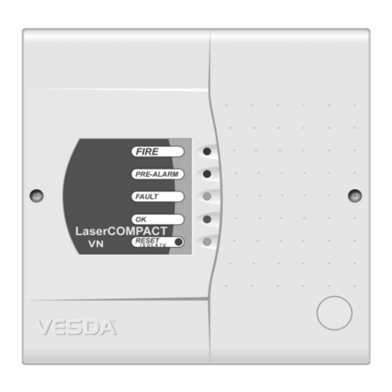
Figure 2 - Operation and internal air flow of LaserCOMPACT Detector LaserCOMPACT display The LaserCOMPACT has five LEDs to indicate Alarms, Faults, OK (normal working of the detector) and Reset/Isolate status. The LaserCOMPACT VN offers the option for a remotely mounted Display Module, see VRT-J00 Display Module mounted into a remote unit on page 5 for details. -
Page 12: Led And Reset/Isolate Button
LaserCOMPACT Product Guide ® LED and Reset/Isolate button The LED indicators and the Reset/Isolate button on the front cover of the LaserCOMPACT detector display alarms and faults. Fire This (RED) LED is lit when the Fire alarm threshold is reached. -
Page 13: Compact (Vn) Remote Display Module
LaserCOMPACT Product Guide Compact (VN) Remote Display Module The LaserCOMPACT (VN) model has the option of being connected to a Remote Display Module mounted into a Mounting Unit or a 19” Subrack. Unlike the LaserPLUS and the LaserSCANNER detectors, the display module cannot be mounted into the LaserCOMPACT. -
Page 14: Lasercompact Remote Display Module
Urgent - Indicates a serious fault requiring immediate attention System - Indicates a fault in the network Zone -Indicates a fault in the VESDA Zone monitored by the Display Module Power - Indicates a fault in the power supply (If the GPI Function is used) - Page 15 Sensitivity: Shows the level of smoke that must be measured to illuminate the entire bar graph and always corresponds with the fire alarm level. Smoke Level: Indicates the current level of smoke in the relevant VESDA address and is represented as % obs/m or % obs/ft.
-
Page 16: Lcd Programmer
LCD Programmer The VESDA LCD Programmer allows configuring, commissioning and maintenance of the VESDA system. For further information please see the LCD Programmer Product Guide. A hand-held programmer can be connected to the LaserCOMPACT VN Models (VLC-505). The VESDAnet socket and VESDAnet terminals can be found on the termination card and can be accessed by removing the front cover of the detector. -
Page 17: Product Configuration
VESDA ® LaserCOMPACT Product Guide Product Configuration Legend Reset/Isolate Button LED indicators Figure 5 - Front view of the LaserCOMPACT detector Legend Programming socket 15 Pin for VN model 9 Pin for RO model Termination card VESDAnet number Air filter cartridge... -
Page 18: Product Information
VESDA LaserCOMPACT Product Guide ® 1.4 Product Information Product Specification Supply Voltage 18 to 30 VDC Power Consumption 5.4 W during normal operation, 5.9 W with alarm on Current Consumption 225 mA at 24 VDC normal operation, 245 mA with alarm on Fuse Rating 1.6A... - Page 19 (Volatile Event Log) Smoke level, alarms and faults with time and date stamp AutoLearn: Minimum 15 minutes, maximum 15 days. (Recommended minimum period 14 days). During AutoLearn thresholds are NOT changed from pre-set values. Table 2 - LaserCOMPACT detector specifications...
-
Page 20: Product Dimensions
VESDA LaserCOMPACT Product Guide ® Product Dimensions Figure 7 - Dimensions in mm. (inches) for LaserCOMPACT... - Page 21 VESDA ® LaserCOMPACT Product Guide E = Cable Entry Port on rear of enclosure Figure 9 - LaserCOMPACT detector dimensions - rear view...
-
Page 22: Default Settings
Health Check 45 seconds 40 seconds 60 seconds Device ID Name/Location Faults Latched Latched Filter Service Interval 1825 days (5 1 day 1825 days years) (Dependent up (5 years) on environment) Table 3 - Default values for the LaserCOMPACT detector... -
Page 23: Relay Settings And Conditions To Change States
The Bias, Reset (GPI) and LED terminals are located on the termination card (Refer to Figure 14, “LaserCOMPACT termination card VN Model (VLC-505),” on page 19 and Figure 15, “LaserCOMPACT termination card RO Model (VLC-500),” on page 20. These terminals have the... -
Page 24: Mounting The Detector
≤ 2 VDC Detector Reset Table 5 - GPI functions 1.5 Mounting the Detector The VESDA LaserCOMPACT can be mounted onto the wall using the mounting bracket on any suitable secure surface. Note: The detector can only be mounted using the mounting bracket included with the... -
Page 25: Securing The Mounting Bracket
® LaserCOMPACT Product Guide Securing the mounting bracket The mounting bracket for the VESDA LaserCOMPACT is always mounted in the UP direction. The mounting bracket is clearly marked with the word “UP” and an upward pointing arrow. Legend This side to... -
Page 26: Recess Mounting Kit
VESDA LaserCOMPACT Product Guide ® Recess mounting kit These kits are used to house a detector inside a wall cavity. Figure 12 - Recess mounting kit 1.6 Connecting the VCL to the Pipe Network Inlet Pipes The air inlet port is designed to fit a standard pipe of 25 mm (1 in) OD. A 25 mm to 1.050 inches adaptor is included for all USA shipments to fit the Pipe Inlet. -
Page 27: Air Exhaust Pipe
Air Exhaust Pipe Unplug the air exhaust port at the bottom of the detector. If necessary pipe the exhaust back to the relevant VESDA Zone. The maximum suggested length for the exhaust pipe is 4 m (13 ft.) 1.7 Wiring Connections... - Page 28 FAULT (NC) Power (-) Power (+) Power (-) Power (+) NC = Normally Closed NO = Normally Open C = Common LEGEND Terminal A Relays VESDAlink Socket Terminal B 1.6 Amp Fuse Figure 15 - LaserCOMPACT termination card RO Model (VLC-500)
-
Page 29: Vesdanet Terminals (Vn Model Only)
It is recommended that RS 485 (BELDEN 9841 - 120 Ohm) twisted pair cables (or similar) be used. The LaserCOMPACT is shipped without the VESDAnet A and B channels looped. If the detector is not to be networked with other devices, then loop the A and B channels. -
Page 30: Programming Socket
The programming socket on the termination card has 15 pins. Use a LCD Programmer and connect the programmer cable to the 15 pin VESDAnet programming socket. • Use a PC with a VESDA PC-Link HLI and the appropriate data cables to connect to the 15 pin VESDAnet programming socket. • RO model: The programming socket on the termination card has 9 pins. -
Page 31: For Further Information See Auxiliary / Gpi Terminals
Typical Wiring To Fire Alarm Control Panel (FACP) The diagram below shows the correct way to wire VESDA laser detectors to a conventional fire alarm control panel (FACP). It also shows where an End Of Line (EOL) resistor is correctly installed. -
Page 32: Wiring To An Address Loop Module
® Wiring To an Address Loop Module. This wiring example is for wiring VESDA detectors to a typical Address Loop module 3 input 1 output. These are example drawings. Refer to the appropriate product manual for the exact wiring details of the third party equipment. -
Page 33: Battery Back Up
LaserCOMPACT Product Guide 1.9 Battery Back Up The power supply for the LaserCOMPACT detector may be switched to a back up battery in the event of the supply being disrupted. The size of the battery back up is determined by local standards and codes, the total power required by the system, back up time required, allowance for reduction in capacity with age and expected temperature variations. - Page 34 LaserCOMPACT Product Guide ® After installing the LaserCOMPACT detector it is necessary to power up the system. The system takes approximately 15 seconds to power up. If the system fails to power up, check all power wires are secured to its terminals and the polarities of the power wires are correctly terminated.
-
Page 35: Installation Checklist
VESDA ® LaserCOMPACT Product Guide Installation Checklist Site Name Address Detector Serial Number(s) and Date of Manufacture Interface Card Serial Number & Date of Manufacture Name of Installer Signature Date Perform the following checks listed below to ensure that all the necessary items are completed before handing over to a commissioning engineer. -
Page 36: Preliminary Systems Check
® 1.11 Preliminary Systems Check A preliminary systems check is required after installing the LaserCOMPACT detector, before it is commissioned for use. The check can be conducted by connecting the detector to a LCD Programmer or using VSC, or VSM4 PC based software. The preliminary systems check includes: •... -
Page 37: Opening And Closing The Detector
Open the front cover and allow cover to hang by the attached plastic strap Closing the detector Replace the front cover over detector enclosure ensuring the plastic strap and cable loom are not wedged between the cover and enclosure Tighten the two screw Figure 22 - Opening and closing a LaserCOMPACT detector... -
Page 38: Replacing The Aspirator
VESDA LaserCOMPACT Product Guide ® Replacing the aspirator Remove the 4 screws securing the termination card (A) Disconnect the wires on the aspirator (B) Gently pull out termination card (A) from the interface card (You can’t see the interface card, it is connected to the back of the termination card). -
Page 39: Internal Wiring For Lasercompact
ONE Spare Part Part No. Description Normal Mission Service Critical VSP-005 Filter Cartridge VSP-501 LaserCOMPACT Aspirator VSP-502 LaserCOMPACT VN Remote Display Module VSP-510 LaserCOMPACT RO Termination Card (CTC-RO) VSP-515 LaserCOMPACT VN Termination Card (CTC-VN) Table 10 - Recommended spare parts stock... - Page 40 VESDA LaserCOMPACT Product Guide ®...
- Page 41 ..........ii Contact Us ........... i Conventions ........... 18 Inlet Pipes ........31 Internal Wiring Introduction to LaserCOMPACT Detector LaserCOMPACT Remote Box Display Mod- ........14 Default Settings ........14 Delay Times ......... 3 Detection chamber ........7 Isolate button ........
- Page 42 ..... 28 Pipe Integrity Smoke Test VESDAnet model (VLC-505) ........28 Power Supply Configurations of VESDA LaserCOMPACT ........6 Pre-alarm light Detector - Introduction to LaserCOMPACT ........15 Pre-Alarm Relay ........... 1 Detector ......14 Pre-Alarm Threshold ..........22 VN model ....
Need help?
Do you have a question about the LaserCOMPACT and is the answer not in the manual?
Questions and answers