
Related Manuals for VESDA VLQ-100


Summary of Contents for VESDA VLQ-100
- Page 1 VESDA VLQ Product Guide VLQ-100 February 2014 Document: 26104_03 Part Number: 30320...
- Page 3 VESDA by Xtralis VESDA VLQ Product Guide Intellectual Property and Copyright This document includes registered and unregistered trademarks. All trademarks displayed are the trademarks of their respective owners. Your use of this document does not constitute or create a licence or any other right to use the name and/or trademark and/or label.
- Page 4 You will also find instructions on installing, cabling and powering up the detector. This guide is for anyone involved with the design, maintenance and purchasing of a VESDA VLQ system. It is assumed that anyone using this product has the knowledge and appropriate certification from local fire and electrical authorities.
- Page 5 VESDA by Xtralis VESDA VLQ Product Guide Codes and Standards Information for Air Sampling Smoke Detection We strongly recommend that this document is read in conjunction with the appropriate local codes and standards for smoke detection and electrical connections. This document contains generic product information and some sections may not comply with all local codes and standards.
- Page 6 VESDA VLQ Product Guide VESDA by Xtralis This page is intentionally left blank. www.xtralis.com...
-
Page 7: Table Of Contents
VESDA by Xtralis VESDA VLQ Product Guide Table of Contents Introduction Features Product Information How it Works Detector Overview Specifications Dimensions Air Sampling Pipe Network Installation Considerations Pipe Inlets Exhaust Air Air Sampling Configurations Installation Mounting Wiring Specify Backup Battery for Power Supply... - Page 8 VESDA VLQ Product Guide VESDA by Xtralis This page is intentionally left blank. www.xtralis.com...
-
Page 9: Introduction
VESDA VLQ Product Guide Introduction The VESDA VLQ is an Aspirating Smoke Detector (ASD) that provides very early warning of fire conditions by drawing air samples through sampling holes located in an air sampling pipe network. The VESDA VLQ detector is specifically designed to cater for small areas up to 100 m² (1000 ft²). VESDA... -
Page 10: Features
VESDA VLQ Product Guide VESDA by Xtralis Features The VESDA VLQ detector provides the following features: Laser-based absolute smoke detection Clean air barriers for optics protection Up to 100 m² (1000 ft²)coverage Up to 2 x 6m (2 x 20ft) pipes (straight), up to 2 x 9m (2 x 30ft) pipes (branched) -
Page 11: Product Information
Product Information How it Works The VESDA VLQ detector continually samples air from the protected environment via two pipe inlets for the sampling pipes on each side of the pipe inlets (A1, A2). Upon entering the detector, the air passes through respective inlet manifolds (B1, B2) and the aspirators (C1, C2). -
Page 12: Detector Overview
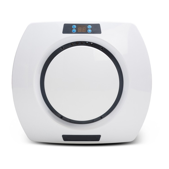
VESDA by Xtralis Detector Overview The VESDA VLQ detector is a lightweight unit designed to be ceiling or wall mounted and operates with a simple sampling pipe network. The detector unit features two sampling pipe inlets, unobtrusive exhaust vents, a simple control panel and display, and a buzzer to provide audio notifications. - Page 13 VESDA by Xtralis VESDA VLQ Product Guide Buttons The VESDA VLQ detector provides accessibility to a range of functions via a set of control buttons. Table 2-2: Control Buttons Button Description Reset / Silence Resetting the detector unlatches all latched alarms and faults, returns relays to their normal state and clears the active event list.
- Page 14 VESDA VLQ Product Guide VESDA by Xtralis Table 2-2: Control Buttons (continued...) Button Description Normalize Airflow / Airflow Normalization sets the reference point for airflow AutoLearn Smoke thresholds based on ambient operating conditions. AutoLearn Smoke sets the alarm thresholds based on the environmental conditions.
-
Page 15: Specifications
Weight 1.2 Kg (2.65 lbs) Operating Conditions Temperature: (To operate the VESDA VLQ detector outside Tested to: -10°C to 55°C (14°F to 131°F) * these parameters please contact your Recommended Ambient: 0°C to 39°C (32°F to 103°F) nearest Xtralis Office.) -
Page 16: Dimensions
VESDA VLQ Product Guide VESDA by Xtralis Table 2-4: Software Features (continued...) Specification Value AutoLearn Smoke Minimum: 15 minutes Maximum: 2 Hours (through Xtralis QSC) Recommended minimum period: 1 hour Thresholds are automatically changed from the previously set values to the updated values after the AutoLearn process has completed. -
Page 17: Air Sampling Pipe Network
Pipe Inlets The VESDA VLQ detector supports two sampling pipes. Both pipes must be connected for proper detector operation. The air inlet ports are tapered such that they accommodate both 25 mm (1 in) or IPS ¾ inch (1.05 in outer diameter) pipes. -
Page 18: Air Sampling Configurations
VESDA VLQ Product Guide VESDA by Xtralis Air Sampling Configurations Both inlets must be fitted with pipes with 1 or 2 holes and the configuration must comply to the rules in Table 3-1 below. Table 3-1: Pipe and Sampling Hole Rules Notes: Ensure that all sampling holes are from within a single space (not physically... - Page 19 VESDA by Xtralis VESDA VLQ Product Guide Table 3-2: Air Sampling Configurations Fire-Alarm Threshold Setting Upper Limit - %/m (%/ft) No. of NFPA76 NFPA76 NFPA76 Sampling Example Detector Configurations Description VEWFD / EWFD / SFD / Locations EN 54-20 EN 54-20 EN 54-20...
- Page 20 VESDA VLQ Product Guide VESDA by Xtralis This page is intentionally left blank. www.xtralis.com...
-
Page 21: Installation
VESDA by Xtralis VESDA VLQ Product Guide Installation The VESDA VLQ detector is shipped with the following components: VESDA VLQ detector, including base Flush Mount or Surface Mount bracket kits (ordered separately) Stub pipes and end caps (ordered separately) Check all components for damage and refer any concerns to your authorized representative. -
Page 22: Mounting
VESDA by Xtralis Mounting Depending on the type of surface, the VESDA VLQ detector can be installed in different ways to suit environmental, aesthetic and local code requirements. There are several mounting techniques described in this section to suit different mounting surfaces The detector base is used in all mounting techniques in conjunction with either the surface mount bracket or flush mount bracket to secure the detector to the mounting surface. - Page 23 VESDA by Xtralis VESDA VLQ Product Guide 1. Secure the Junction Box (A) to the hard surface with appropriate fasteners. 2. Connect wiring conduit (C) to Junction Box and pass the wires through. 3. Remove the detector base from the detector body by holding the detector body and rotating the base anti-clockwise.
- Page 24 VESDA VLQ Product Guide VESDA by Xtralis 4.1.2 Surface Mount on Suspended Ceiling Tile 4.1.2.1 Mounting with Junction Box The Surface Mount Bracket is used behind the ceiling tile to spread the detector fixing load across a weak surface. Legend Generic third party...
- Page 25 VESDA by Xtralis VESDA VLQ Product Guide 1. Remove the ceiling tile on which installation is required. 2. Remove the detector base from the detector body by holding the detector body and rotating the base anti-clockwise. 3. Use Surface Mount Bracket (A) to drill three mounting holes and two wiring holes into the ceiling tile, ensuring that the sampling pipe inlet arrows on the surface mount bracket are appropriately positioned.
- Page 26 VESDA VLQ Product Guide VESDA by Xtralis Legend Remove Shroud Remove pipe-inlet fascia G Remove snapoffs Snapoffs removed Figure 4-10: Remove shroud, pipe inlet fascia and snapoffs 4. Place the Flush Mount Bracket (B) from the top side of the tile and screw the Shroud (E), placed from the bottom side of the ceiling tile.
- Page 27 VESDA by Xtralis VESDA VLQ Product Guide 4.1.3.2 Mounting without Junction Box Legend Ceiling or Ceiling Tile Flush Mount Bracket Detector Base Holes Figure 4-11: Flush Mount on suspended Ceiling Tile with no Junction Box 1. Follow steps 1 to 5 from the previous section.
-
Page 28: Wiring
VESDA VLQ Product Guide VESDA by Xtralis Wiring The terminal block connectors located on the underside of the VESDA VLQ detector will accept 0.2 - 2.5 mm² or 30-12 AWG wire sizes. 4.2.1 Cabling Inlet There are two cabling inlet ports. The ports are fitted with rubber grommets. They are not intended for wiring conduit connections. - Page 29 Typical Wiring to a Fire Alarm Control Panel (FACP) The diagram below shows the correct way to wire VESDA detectors to a conventional fire alarm control panel (FACP). It also shows where an End Of Line (EOL) resistor is correctly installed.
- Page 30 4.2.7 Wiring to an Addressable Loop Module This wiring example is for wiring VESDA detectors to a typical Input/Output Loop module 3 inputs 1 output. Note: These are example drawings. Refer to the appropriate product manual for the exact wiring details of the third party equipment.
-
Page 31: Specify Backup Battery For Power Supply
VESDA by Xtralis VESDA VLQ Product Guide Specify Backup Battery for Power Supply In the event of a mains power supply disruption, the VLQ detector runs on a backup battery connected to the external power supply. The size of the battery is determined by:... -
Page 32: Installation Checklist
VESDA VLQ Product Guide VESDA by Xtralis Installation Checklist Site Name Address Detector Serial Number(s) and Date of Manufacture Name of Installer Signature Date Perform the following checks listed below to ensure that all the necessary items are completed before handing over to a commissioning engineer. -
Page 33: Powering Up
The VESDA VLQ detector does not have a power switch, i.e it is hard wired to a 24 VDC supply and it is assumed that the power supply has been installed as per manufacturers instructions in accordance with local electrical codes. - Page 34 VESDA VLQ Product Guide VESDA by Xtralis This page is intentionally left blank. www.xtralis.com...
-
Page 35: Configuration
VESDA VLQ Product Guide Configuration The VESDA VLQ detector is configured using the Xtralis QSC software or onboard DIP switches. Logging on using the Display Panel Prior to configuring or operating the detector using the display panel controls, it is necessary to log in to the detector. -
Page 36: Dip Switch Configuration
VESDA VLQ Product Guide VESDA by Xtralis DIP Switch Configuration The VESDA VLQ provides a range of configuration options using an on-board DIP Switch bank. Figure 5-1: DIP Switch Location Table 5-1: DIP Switch Configuration Switch Position Purpose Configuration Options Default Switch Settings SW1 SW2 SW3... -
Page 37: Commissioning
The detector is monitored during commissioning using Xtralis QSC. Once the VESDA VLQ detector has been commissioned, it will report alarms and faults according to the parameters defined during installation. - Page 38 VESDA VLQ Product Guide VESDA by Xtralis This page is intentionally left blank. www.xtralis.com...
-
Page 39: Xtralis Qsc Software
VESDA VLQ Product Guide Xtralis QSC Software Xtralis QSC is used for configuration and commissioning of the VESDA VLQ detector. Buttons are green and change to pink when active, and only when logged on to VESDA VLQ are all the buttons are visible. Installation 1. -
Page 40: Configuration
VESDA VLQ Product Guide VESDA by Xtralis Table 7-1: Xtralis QSC Commands (continued...) Button / Function Action Set Time Allows setting of the detector time, chose set to PC time for this version Get Event Log Allows to log up to last 1000 events and stores in a CSV file (do not change... -
Page 41: Device Information
VESDA by Xtralis VESDA VLQ Product Guide Device Information Table 7-3 below details information for the VLQ available in the Xtralis QSC software, under Device Information. Table 7-3: Device Information Item Description Model Displays model number Serial Number Displays serial number Hardware Version... - Page 42 VESDA VLQ Product Guide VESDA by Xtralis This page is intentionally left blank. www.xtralis.com...
-
Page 43: Maintenance
VESDA by Xtralis VESDA VLQ Product Guide Maintenance To maintain the VESDA VLQ detector at its peak performance level, the recommended maintenance schedule shown in Table 8-1 below should be followed. Table 8-1: Recommended maintenance schedule for the VESDA VLQ detector Maintenance Check... - Page 44 VESDA VLQ Product Guide VESDA by Xtralis Figure 8-2: Remove filter retaining bracket Where the filter is secured with retaining clips: Whilst holding the filter housing (B), loosen the screws C and D with a Philips head screwdriver.turn the clips (E and F) outwards, away from the magnets beneath them (Figure 8-3).
- Page 45 VESDA by Xtralis VESDA VLQ Product Guide Figure 8-4: Remove Filter Filter Insertion Procedure 1. With the filter removed from the detector, pressing Test and Disable button simultaneously displays filter use percentage value. When a new filter is used reset the filter use percentage value. To do this, press the Reset button on the front panel once, or use the Xtralis QSC software.
- Page 46 VESDA VLQ Product Guide VESDA by Xtralis This page is intentionally left blank. www.xtralis.com...
-
Page 47: Troubleshooting
VESDA by Xtralis VESDA VLQ Product Guide Troubleshooting Fault Codes Fault codes can be viewed on the LED display or by using the Xtralis QSC software. Faults 01 though to 18 are hardware faults which require that the detector be replaced. Faults 41 through to 50 are generally rectifiable with minimal user interaction. - Page 48 VESDA VLQ Product Guide VESDA by Xtralis Table 9-1: Fault Codes (continued...) Fault Code Fault Type Description Possible Resolution Autolearn Smoke Failed The detector has been unable to Re-activate when area is establish suitable alarm thresholds smoke-free, or set suitable during Autolearn Smoke.
- Page 49 VESDA by Xtralis VESDA VLQ Product Guide Table 9-1: Fault Codes (continued...) Fault Code Fault Type Description Possible Resolution External Device on GPI External device failure Check that the EOL resistor is fitted. Examine monitored device (if fitted). Refer to Section 4.2.5 on page 23 for further information.
- Page 50 VESDA VLQ Product Guide VESDA by Xtralis This page is intentionally left blank. www.xtralis.com...
Need help?
Do you have a question about the VLQ-100 and is the answer not in the manual?
Questions and answers