
Related Manuals for VESDA LaserSCANNER VLS-200


Summary of Contents for VESDA LaserSCANNER VLS-200
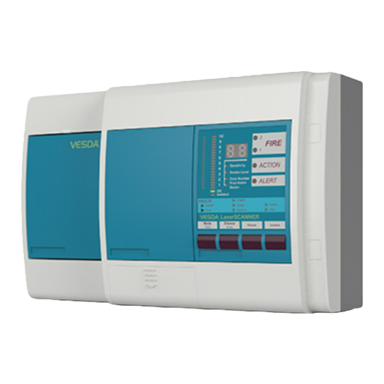
- Page 1 ® ® ™ LaserSCANNER INSTALLATION MANUAL VLS Models VLS-200 VLS-204 VLS-214 VLS-300 VLS-304 VLS-314 VLS-600 VLS-700 October 2005 Version 1.3...
- Page 2 Disclaimer The manufacturer reserves the right to change designs or specifications without obligation and without further notice. VESDA, LaserTEKNIC, LaserPLUS, LaserSCANNER, LaserCOMPACT, VESDAnet, VESDAlink, ASPIRE, AutoLearn, VSM, VConfig, InfoWORKS, PROACTIV and PRECISION are trademarks used under licence by the distributor.
-
Page 3: Table Of Contents
Power Up ........................19 7.1Power Up the System......................19 Preliminary System Checks ..................20 8.1Logging On to the System ....................20 8.2VESDAnet Communication Check ..................20 8.3Normalise the Air Flow and Clearing Air Flow Faults............21 8.4Basic Pass/Fail Smoke Test....................22 Installation Checklist ....................23 VESDA Product Warranty Conditions ..............24... -
Page 4: Introduction
This manual is intended for installation technicians to be able to install, perform basic power and preliminary device checks for the LaserSCANNER detector. It does not cover information for commissioning. All VESDA equipment is to be commissioned by personnel who have attended a VESDA accreditation course. -
Page 5: Cabling Requirements
VESDA ® LaserSCANNER Installation Manual 2. Cabling Requirements The terminals on the termination card in the LaserSCANNER will accept wire sizes up to 2.5sq mm (12 AWG). 2.1 Power Cables Use the power ratings for the detector and the modules to determine the required wire sizes. -
Page 6: Laserscanner Specifications
VESDA ® LaserSCANNER Installation Manual 3. LaserSCANNER Specifications Supply Voltage 18 to 30VDC Power Consumption See table 1, page 2 Dimensions (WHD) 350mm x 225mm x 125mm (13.8in x 8.9in x 4.9in) Weight 4.0kg (9lbs) including Display and Programmer module Operating Temperature Tested to:-10°... -
Page 7: Laserscanner Dimensions
VESDA ® LaserSCANNER Installation Manual 4. LaserSCANNER Dimensions 350 (13.8) 35.0 51.0 (2.0) (1.37) 21.0 (0.83) Bridge and Lance (7.87) (8.9) 77.5 (3.05) 28.5 (1.12) (12.56) 209 (8.24) 207 (8.15) Mounting Bracket 12.0 (0.47) CE = Cable Entry Ports (25.4mm, 1.0in ∅) - Page 8 VESDA ® LaserSCANNER Installation Manual 350(13.8) 34.0 45.0 (1.37) (1.33) (1.33) (1.33) (1.33) (1.77) 26.0(1.02) 26.0 (1.02) Inlet Air Ports TOP VIEW 26.0 125 (4.9) (1.02) (8.9) 28.5 (1.12) RIGHT HAND LEFT HAND FRONT VIEW SIDE VIEW SIDE VIEW BOTTOM VIEW 26.0...
-
Page 9: Battery Backup Calculations
5. Battery Backup Calculations The nominal supply voltage is 24 VDC. Use Table 2 to calculate and to determine the battery backup requirements for your VESDA system. Refer to Table 1, page 3 for power consumption details. NORMAL LOAD @ 24 V DC... -
Page 10: Installation
VESDA ® LaserSCANNER Installation Manual 6. Installation 6.1 Check Procedure Before Installation (a) Do not install your LaserSCANNER if there are any signs of shipping damage to the product. Inform your distributor if there is any damage. (b) Check the model of the LaserSCANNER is correct as per the design specifications for the site. -
Page 11: Removal Of
VESDA ® LaserSCANNER Installation Manual 6.2 Removal of Front Cover (a) Insert a 4mm x 1mm flat blade screwdriver (A) into notch. Refer to Figure 4. (b) Gently open the blank plate (B) with the screwdriver. (c) Lift out the two screw covers (C) with a flat blade screwdriver. -
Page 12: Component Location Inside Detector Enclosure
VESDA ® LaserSCANNER Installation Manual 6.3 Component Location inside Detector Enclosure CPU Card Wire Terminal Strips (Under Backing Sheet) Termination Card (7 Relays) or optional 12 Relays Card VESDAnet socket Aspirator FOK LED Connector VESDAnet Laser Detector Air Filter Cartridge... -
Page 13: Removal Of Metal Knockout Holes For Cable Entry
VESDA ® LaserSCANNER Installation Manual 6.5 Removal of Metal Knockout Holes for Cable Entry (a) Determine the cable entry holes to be used. Refer to Figure 7. (b) Using the ball end of a small hammer, gently tap onto the required knockout holes to break away the metal pieces. -
Page 14: Securing The Mounting Bracket
VESDA ® LaserSCANNER Installation Manual 6.7 Securing the Mounting Bracket Warning: Make sure that there are no electrical wires or plumbing behind the mounting position before drilling. Ensure the mounting position is flat. a) Remove the drilling template from the centre page of this manual. -
Page 15: Connecting The Air Sampling Pipe
VESDA ® LaserSCANNER Installation Manual 6.9 Connecting the Air Sampling Pipe The air inlet ports are designed to fit a standard pipe of 25mm (1in) OD. A tapering of the air inlet ports prevent the pipes from being inserted beyond 15mm (5/8in). -
Page 16: Termination Card Details
VESDA ® LaserSCANNER Installation Manual 6.11 Termination Card Details Terminal A Terminal B Terminal C Pin 1 Pin 1 Pin 1 Terminal A Terminal B Terminal C 1 VESDAnet A+ 1 Isolate (NO) 1 Fire 2 (NC) 2 VESDAnet A-... -
Page 17: Terminating The Power Wires To The Termination Card
VESDA ® LaserSCANNER Installation Manual (c) On the termination card, remove the plugs from its terminal sockets. (d) Insert the correct wires into the terminal plugs. (e) Tighten terminal plug screw. (f) Repeat steps (c) to (e) as required. (g) Insert plugs into the correct sockets on the termination card. -
Page 18: Terminating The Relay Wires To The Termination Card
VESDA ® LaserSCANNER Installation Manual Detector 1 Detector 2 Detector 3 ½ Terminal A ½ Terminal A ½ Terminal A Shield Shield Shield Shield Shield Shield Shield Shield Shield Shield Detector 5 Detector 4 ½ Terminal A ½ Terminal A Figure 12 Wire Connection Details for VESDAnet (Closed Loop) ½... - Page 19 VESDA ® LaserSCANNER Installation Manual Terminal B Terminal C Fire 2 Isolate (Relay 7) (Relay 1) Minor Fault Fire 1 (Relay 2) (Relay 6) Urgent Fault Action (Relay 3) (Relay 5) GPI- Alert GPI+ (Relay 4) Terminal Pins location for 7 Relays (Default Relay Assignments)
-
Page 20: Closing Up The Laserscanner
VESDA ® LaserSCANNER Installation Manual 6.16 Closing Up the LaserSCANNER a) Tie all wires together into neat looms using cable ties. b) If the front cover was removed do the following:- Reattach the plastic straps to the front cover. Re-connect the removed cable loom to the Term socket located on the rear of the display or programmer module. -
Page 21: Power Up
The aspirator starts up and air is felt flowing out of the exhaust port. If a Programmer module is fitted, the VESDA name will appear on the LCD screen. If a Display module is fitted, the following indicators are lit:- •... -
Page 22: Preliminary System Checks
VESDA ® LaserSCANNER Installation Manual 8. Preliminary System Checks Perform the following preliminary system Setup and checks before commissioning. (a) Logging onto the system with a PC or a LCD Programmer. See Section 8.1. (b) VESDAnet communication checks. See section 8.2 (c) Normalise the airflow. -
Page 23: Normalise The Air Flow And Clearing Air Flow Faults
VESDA ® LaserSCANNER Installation Manual 8.3 Normalise the Air Flow and Clearing Air Flow Faults Note: This procedure normalises the airflow for all pipes in use and takes approximately 11 minutes. It is important to correctly select the pipes in use before Normalising. Check the airflow is approximately 100% when completed. -
Page 24: Basic Pass/Fail Smoke Test
VESDA ® LaserSCANNER Installation Manual 8.4 Basic Pass/Fail Smoke Test Note: This test verifies the detector will sense smoke. It does not replace any appropriate commissioning test. Use the table below to perform this test by using one of the following devices. -
Page 25: Installation Checklist
VESDA ® LaserSCANNER Installation Manual 9. Installation Checklist Site Name: ……………………………………………………………………… Zone: …………………………………………………………………………….. Detector Serial Number/s: …………………………………………………… Perform the following checks listed below to ensure that all the necessary items are completed before handing over to a commissioning engineer. INSTALLATION CHECKS 1. -
Page 26: Vesda Product Warranty Conditions
LaserSCANNER Installation Manual 10. VESDA Product Warranty Conditions 1. Vision Systems warrants that new VESDA products (excluding consumable items) will conform to its published specifications and remain in good working order during the warranty period of 24 (twenty four) months from date of shipment from Vision Systems. - Page 27 Australia and Asia The Americas Europe and the Middle East Vision Fire & Security Vision Fire & Security Vision Fire & Security Private Bag 215 700 Longwater Drive Vision House, Focus 31 Mark Road 495 Blackburn Road Norwell, MA 02061, USA...
Need help?
Do you have a question about the LaserSCANNER VLS-200 and is the answer not in the manual?
Questions and answers