Table of Contents
Advertisement
Advertisement
Table of Contents

Related Manuals for 2N IP Series


Summary of Contents for 2N IP Series
- Page 1 Configuration manual for 2N IP intercoms v.2.43 www.2n.com...
-
Page 2: Table Of Contents
Configuration manual for 2N IP intercoms Content: • 1. Product Overview • 2. Express Wizard for Basic Settings • 3. Model Differences and Function Licensing • 3.1 Model Differences • 3.2 Function Licensing • 4. Signalling of Operational Statuses •... - Page 3 Configuration manual for 2N IP intercoms • 5.5.8 Digital Inputs • 5.5.9 Extenders • 5.5.10 Lift Control • 5.6 System • 5.6.1 Network • 5.6.2 Date and Time • 5.6.3 Features • 5.6.4 License • 5.6.5 Certificates • 5.6.6 Auto Provisioning •...
-
Page 4: Product Overview
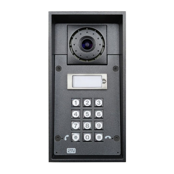
Some 2N IP intercom models are equipped with a numeric keypad, which can be used as a code lock or a standard push-button phone. The 2N IP intercoms help LAN users scan the area in front of the camera via video streaming. Thanks to the full ONVIF support, the intercoms can become part of the Video Surveillance System in your facility. - Page 5 Configuration manual for 2N IP intercoms The following symbols and pictograms are used in the manual: Safety • Always abide by this information to prevent persons from injury. Warning • Always abide by this information to prevent damage to the device.
-
Page 6: Express Wizard For Basic Settings
Chrome, Firefox or Internet Explorer 9+ versions 2N IP intercom is not fully compatible with earlier browser versions. Use the name admin and password 2n (i.e. default reset password) for your first login to the configuration interface. The intercom requires a password change upon the first login. Strong passwords are only accepted - eight characters at least including one capital letter, one small letter and one digit. ... - Page 7 Configuration manual for 2N IP intercoms Firmware Upload We also recommend you to update your intercom firmware upon the first login to the intercom. Refer to www.2n.cz for the latest firmware version. Press the Update Firmware button in the System / Maintenance menu to upload firmware. The intercom will get restarted upon upload and only then the updating process will be complete.
- Page 8 Configuration manual for 2N IP intercoms • Proxy address – set the SIP Proxy IP address or domain name. • Proxy port – set the SIP Proxy port (typically 5060). • Backup Proxy Address – set the SIP Proxy IP address or domain name to be used where the main proxy fails to respond to requests. The address is used where the main proxy fails to respond to requests. • Backup Proxy Port – set the backup SIP Proxy port (typically 5060). ...
- Page 9 Quick Dial Button Settings All the 2N IP intercom models are equipped with quick dial buttons. If you press a quick dial button, a call will be set up to the phone number assigned to the respective Users list position.
- Page 10 Configuration manual for 2N IP intercoms You can also use the 2N IP intercom with one or more IP phones without a SIP server. Use the Direct SIP Call. For outgoing calls and enter the called phone SIP address (sip:phone_number@phone_ip_address) instead of the phone number.
- Page 11 Configuration manual for 2N IP intercoms Enable the switch in the Switch Enabled parameter in the Hardware / Switches / Switch 1 tab, set the Controlled Output to the intercom output to which the electric door lock is connected. Now set one or more activation codes for the electric door lock switching. ...
-
Page 12: Model Differences And Function Licensing
Central and South America. 3.1 Model Differences This manual is valid for all members of the 2N IP intercom family and so some features described herein are only available in selected 2N IP intercom models or need to be activated with a valid license key. This section provides a short list of differences between the models and licenses which affect the configuration options. - Page 13 Configuration manual for 2N IP intercoms Property/ ® ® ® ® ® ® ® ® ® ® ® Model Style Verso Verso Solo Vario Forc Safet Audi Vide o Kit o Kit Part No. 9157 9155 9155 91553 9137 2...
- Page 14 Configuration manual for 2N IP intercoms Property/Model ® ® ® ® ® ® ® ® ® ® ® Style Verso Verso Video Vari Basic unit 1, 3 up to 16 button count external programm able buttons Button up to 145...
-
Page 15: Function Licensing
® Eye support Telephone mode Some of the 2N IP intercom functions are only available if the valid license key is entered (refer to the License subsection). 3.2 Function Licensing Feature Licensing A standard license included in the device is mostly sufficient for a common use of the 2N IP intercom. - Page 16 Configuration manual for 2N IP intercoms License Types Some 2N IP intercom functions are unavailable until a valid license key is entered (refer to the License subsection). The following types of licenses are available: • NFC (included in device) • Enhanced Audio (included in device) •...
- Page 17 Configuration manual for 2N IP intercoms Function Enhanc Enhanc Enhanc Enhanc Inform Licence ed aCast interco ms Lift Audio Video Integrat Securit module license User sounds • included in device Automatic audio • included test in device Noise detection •...
- Page 18 Configuration manual for 2N IP intercoms Function Enhanc Enhanc Enhanc Enhanc Inform Licence ed aCast interco ms Lift Audio Video Integrat Securit module license Motion detection • GOLD support Extended switch • GOLD setting options HTTP API (see • included...
- Page 19 Gold license, so the only possible upgrade is InformaCast. How do I get the license? Licenses are generated by 2N according to the particular serial number. After you decide which license you want, you need to get the serial number of your unit and contact your distributor for the license key.
- Page 20 Licenses can be downloaded automatically in the System / License menu. FAQ: License for 2N IP intercoms – How to get it Can I have a demo license? Yes, there is an option for an 800-hour trial Gold license period during which you can try the licensed features.
-
Page 21: Signalling Of Operational Statuses
Configuration manual for 2N IP intercoms 4. Signalling of Operational Statuses 2N IP intercom generates sounds to signal switching and changes of operational statuses. Each status change is assigned a different type of tone. See the table below for the list of signals. - Page 22 Installation Manual for details. Call end signalling 2N IP intercom enables the user to set a call end timeout to avoid call blocking. Press a key on your VoIP phone to extend the call time during this timeout. The purpose of the timeout setting is to avoid call blocking.
-
Page 23: Intercom Configuration
Configuration manual for 2N IP intercoms 5. Intercom Configuration Web Configuration Interface Login The device is configured via a web configuration interface. You need to know the device IP address and domain name to get access. Make sure that the device is connected to the local IP network and properly powered. - Page 24 The start screen is also the first menu level and quick navigation (click on a tile) to selected intercom configuration sections. Some tiles also display the state of selected services. Configuration Menu The 2N IP intercom configuration includes 5 main menus: State, Directory, Hardware, Services and System including submenus; see below. Status •...
- Page 25 Configuration manual for 2N IP intercoms • Services – information on active services and their states • License – current states of licenses and available intercom functions • Access Log – last 10 access logs • Call Logs – last 20 accomplished calls •...
- Page 26 Configuration manual for 2N IP intercoms • Backlight – backlight intensity setting • Display – basic display settings • Card Reader – card reader, Wiegand interface settings • Digital Inputs – digitial input settings ® • Extenders – 2N IP Verso extender settings • Lift Control – floor lift access settings System •...
- Page 27 / device in contradiction to the manufacturer’s instructions, guidelines or recommendations or in conjunction with unsuitable products / devices of other suppliers, the customer agrees that the 2N TELEKOMUNIKACE a.s. company shall not be held liable for any functionality limitation of such a product or any damage, loss or injury related to this potential functionality limitation.
-
Page 28: Status
Configuration manual for 2N IP intercoms 5.1 Status The Status menu provides clear status and other essential information on the intercom. The menu is divided into five tabs: Device, Services, Access Log, Call Log and Events. Device The Device tab displays basic information on the intercom model, its features, firmware and bootloader versions and so on. - Page 29 Configuration manual for 2N IP intercoms • Locate Device – optical and acoustic signaling of a device. Optical signaling is possible ® ® ® only if the device is equipped with control backlight (2N IP Style, 2N IP Verso, 2N IP ® ®...
- Page 30 Configuration manual for 2N IP intercoms 30 / 282...
- Page 31 Configuration manual for 2N IP intercoms Access Log The Access Log tab displays the last 10 records on applied cards. Each record includes the card tapping time, card ID and type and description details (validity, card owner, etc.). 31 / 282...
- Page 32 Configuration manual for 2N IP intercoms Call Log The call log provides a list of all accomplished calls. Each call includes the contact type, called/ calling user ID, call date and time, call duration and status (incoming, outgoing, missed, picked up elsewhere, doorbell button).
- Page 33 Configuration manual for 2N IP intercoms • – press the button to export all recorded events to a CSV file. Event Description AccessLimite Event generated after 5 unsuccessful user authentication atttempts (card, code, fingerprint). The access module gets blocked for 30 seconds even if the subsequent authetication is correct.
- Page 34 Configuration manual for 2N IP intercoms Event Description CallSessionSt Event describing the call direction/state, address, session number and call ateChanged sequence number. CallStateCha Indicates the call direction (incoming, outgoing) and opponent / SIP account nged identification at a call state change (ringing, connected, terminated).
- Page 35 Configuration manual for 2N IP intercoms Event Description LiftStatusCha Detection of Lift Control module connection/disconnection. nged LoginBlocked Event generated after 3 wrong logins to the web interface. Contains information about IP address. MobKeyEnter Bluetooth authorization. MotionDetect Generated after motion detection, settings can be made in Hardware / Camera / Internal Camera.
-
Page 36: Directory
Configuration manual for 2N IP intercoms Event Description UserAuthenti Signals user authentication and subsequent door opening. cated UserRejected User rejection. VirtualInput Virtual input change. VirtualOutput Virtual output change. CallSessionSt Informs of the current call phase (initialized, connecting, ringing, connected, ateChanged terminated). - Page 37 The Users list contains up to 10 000 users (variable in the 2N IP intercom models). Also includes the users that can be called via the quick dial buttons and the users that are assigned the RFID card, code, etc.
- Page 38 Warning ® • You are not advised to edit the device directory that is managed by 2N Access ® Commander via the device web interface. Due to synchronization with 2N Access Commander the directory changes made via the web interface will be lost.
- Page 39 Configuration manual for 2N IP intercoms The Search in directory function works as a fulltext search in user names, phone numbers and e- mail addresses. It searches for all matches in the list. Press the button above the table to add a User.
- Page 40 Configuration manual for 2N IP intercoms Caution • Special users such as those created by My2N or 2N Access Commander are not part of the directory export. • While editing the CSV file using Microsoft Excel, remember to save the file in the CSV UTF-8 format (with separators).
- Page 41 Configuration manual for 2N IP intercoms Caution • If the cropped image does not fill the whole crop window space, the resultant ® picture is centered on 2N IP Style. • E-mail – user e-mail address for sending missed call information. You can enter more e- mail addresses separated with commas.
- Page 42 Phone Number – enter the phone number of the station to which the call shall be routed. Enter the address sip:[user_id@]domain[:port] for Direct SIP calling, e.g.: sip:200@192.168.22.15 or sip:name@yourcompany. For local calls to the 2N IP intercoms and answering units enter device:device ID. Set the device name in the respective devices. For calls to Crestron enter RAVA:device_name. Enter /1 or /2 behind the phone...
- Page 43 Call Type – set the scheme in the called destination URI. If you choose Without scheme, the URI is completed with the data from the SIP account settings. Further settings include direct SIP calls (sip:), 2N local calls (device:), Crestron calls (rava:) or calls with video management systems, e.g. AXIS Camera Station (vms:).
- Page 44 When Enhanced Integration is not licensed on a device, it is possible to control the ® locks only when a call is in progress. If a call with user, who has 2N IP Eye address filled in, is in progress, no license is needed to control the locks.
- Page 45 Configuration manual for 2N IP intercoms • Entry Rules • Access Enabled – enable authentication via this access point. • Access Profiles – select one of the profiles pre-defined in Directory / Time profiles or set the time profile for this element manually.
- Page 46 Configuration manual for 2N IP intercoms • Valid to – set the end of the mode validity term. Leave empty so that the end is not restricted. Valid To must be after Valid From. • Access Exception – enable this user to bypass Access Blocking and Anti-Passback rules.
- Page 47 Virtual Card ID – set the user virtual card ID for user identification in the devices that are integrated with the 2N IP intercoms via a Wiegand interface. Each user can be assigned just one virtual card. The virtual card ID is a sequence of 6–32 characters: 0–9, A–F. After the user is validated via the Bluetooth/biometric reader, the identifier is sent to the device integrated with the 2N IP intercom via Wiegand.
- Page 48 Configuration manual for 2N IP intercoms Pairing via Bluetooth Module in Intercom To pair a mobile phone with the user: • Click at Auth ID to start pairing for the selected user account. • A dialogue window with the PIN code is displayed.
- Page 49 Refer to Subs. 5.2.1.1 User Fingerprint Setting Instructions for user fingerprint loading details. The 2N IP intercom helps you use the recognized license plates sent in the HTTP request by the AXIS cameras equipped with additional VaxALPR to api/lpr/licenseplate (refer to the HTTP API Manual for IP Intercoms for more...
- Page 50 Configuration manual for 2N IP intercoms • Floors – select the floors available to the user. • Time Profile – select one or more time profiles to be applied. Set the time profiles in the Directory / Time Profiles section. • mark the selection from predefined profiles or manual setting of a time profile for the given element.
-
Page 51: Call Connection Settings
Tlačítka. Make sure that Local calls is enabled on the called 2N device to make a successful call. Connection with Other Devices Click Add user above the table to create a new contact or open an existing contact detail. Click the pencil icon next to the Phone number to open phone number editing. -
Page 52: User Fingerprint Setting Instructions
Load via fingerprint reader module in Directory / Users/ User fingerprints. ® 1b) To load fingerprints via an external USB fingerprint scanner, use the 2N IP USB Driver and select Fingerprint reader in the Settings and press OK for confirmation. Click Load via fingerprint reader module in Directory / Users/ User fingerprints via the web interface at the... - Page 53 Configuration manual for 2N IP intercoms 53 / 282...
- Page 54 Configuration manual for 2N IP intercoms 2) Click to select a finger for fingerprint loading. Up to two fingerprints may be saved for each user. 3) Click SCAN FINGER to load a fingerprint. 54 / 282...
- Page 55 Configuration manual for 2N IP intercoms 4) Place the selected finger on an external USB reader. This process is repeated three times for greater precision. Repeat the process if any inconsistency occurs during fingerprint reading. 55 / 282...
- Page 56 Configuration manual for 2N IP intercoms 5) If fingerprint scanning is successful, click DONE to confirm the settings. To set the finger function, click the icon to display the list of available functions: • Open door • Silent Alarm; only if Open door is active •...
- Page 57 Configuration manual for 2N IP intercoms Click SAVE AND QUIT to confirm the fingerprint enrolment and selected functions. 6) You can check the current settings in the User tab. 57 / 282...
-
Page 58: Usb Rfid Card Reader
It is possible to read the card ID via an RFID card reader. Proceed as follows: • Go to the 2N USB Driver settings. • Set up the COM port for the connected reader. • Press the Read button via the 2N IP intercom web interface. 58 / 282... - Page 59 Configuration manual for 2N IP intercoms • Tap the card on the card reader. • The card ID is successfully read. Do not forget to save the configuration. 59 / 282...
-
Page 60: Time Profiles
Assign a time profile according to a week time sheet to define availability of the selected function. Just set from-to or days in the week on which the function shall be available. 2N IP intercom helps you create up to 20 time profiles (depending on the 2N IP intercom model) that can be assigned to the function;... - Page 61 Configuration manual for 2N IP intercoms List of Parameters • Profile name – enter a profile name. This parameter is optional and helps you find items in the time profile list and select profiles in the switch, card and phone number settings more easily.
- Page 62 Configuration manual for 2N IP intercoms If a day is marked as holiday (refer to Directory → Holidays), the last table row (Holiday) is applied regardless of the day in a week. Make sure that the real time settings are correct (refer to the Date and Time subsection) to make this function work properly. ...
-
Page 63: Holidays
Configuration manual for 2N IP intercoms 5.2.3 Holidays Here select the bank holidays (including Sundays). You can assign them different time intervals than to working days in their time profiles. You can set holidays for the coming 10 years (click the year number at the top of the screen to select a year). -
Page 64: Calling
• RTP (Real-Time Transport Protocol) – is a protocol defining the standard packet format for audio and video transmission in IP networks. 2N IP intercom uses the RTP for audio and video stream transmission during a call. The stream parameters (port numbers, protocols and codecs) are defined and negotiated via the SDP (Session Description Protocol). -
Page 65: General Settings
Control Protocol (TCP), which is less frequent, yet recommended unsecured signalling method • via the Transaction Layer Security (TLS) protocol, where SIP messages are secured ® against third party monitoring and modification (except models 2N IP Base, Uni) Here is what you can find in this section: • 5.3.1 General Settings •... - Page 66 Configuration manual for 2N IP intercoms • Automatic – the intercom picks up incoming calls automatically. You can set the call receiving mode for each SIP account separately. • Automatic (DTMF only) – the intercom picks up incoming calls automatically only if DTMF without connection to a microphone and speaker is received.
- Page 67 Configuration manual for 2N IP intercoms Connecting Time Limit – set the maximum outgoing call connection timeout after which the calls are automatically terminated. If the calls are routed to the GSM network via GSM gateways, you are advised to set a value higher than 20 s.
- Page 68 Configuration manual for 2N IP intercoms • Maximum Number of Dialed Digits – set the maximum count of digits for a phone number in the Telephone mode. When this limit is reached, the number is dialed automatically without pressing *. •...
- Page 69 Configuration manual for 2N IP intercoms Example 1 The algorithm first resolves the branches independently of each other. There are users Alice and Carol configured to one button in the example below (by pressing the button two parallel calls are initiated together). The Dial Cycles Limit is set to 2. Alice has two phone numbers (calling destinations), the other users have only one calling destination.
- Page 70 Configuration manual for 2N IP intercoms Example 2 Let’s take the previous example and change the deputy of Dave to Bob. This way the two branches are merged (only one call takes place from step 3 further on). You can also see that Alice is eventually called three times.
- Page 71 Configuration manual for 2N IP intercoms Example 3 Let’s take the configuration from Example 1 and consider a situation that Alice rejects the call from her first destination. The algorithm skips dialing this destination further on (since the user actively rejected the call and it makes no sense to call them again). The calling groups in individual steps are therefore dynamically modified when one or more users reject the call from various calling destinations.
- Page 72 Configuration manual for 2N IP intercoms Example 4 It is possible that two calling destinations of a single user are called at once. This can be achieved by configuring the scheme similarly to the example below but this situation may also arise from skipping of the destinations that rejected the call previously.
- Page 73 Configuration manual for 2N IP intercoms 5.3.2 Dialing Quick Dial Buttons Assign the Directory > Users users to the quick dial buttons. By default, all available intercom buttons are assigned to the listed users. A non-assigned button can be used for automation or ® ...
- Page 74 Configuration manual for 2N IP intercoms Info • Up to 16 users can be assigned to one speed dial button. • The maximum total count of numbers called in parallel is 16. This can occur in the case of group call and multiple called users assigned to one quick dial button.
- Page 75 Configuration manual for 2N IP intercoms The created folders and users are displayed to the left. Click to add a folder. Click remove a directory including users and groups. Click to rename a group. Click to move a user from the main tree to a folder.
- Page 76 5.3.3 SIP 1 / SIP 2 The 2N IP intercoms allow two independent SIP accounts to be configured. Thus, the intercom can be registered under two phone numbers, with two different SIP exchanges and so on. Both the SIP accounts process incoming calls equivalently.
- Page 77 Configuration manual for 2N IP intercoms • Display Name – set the name to be displayed as CLIP on the called party's phone. • Phone Number (ID) – set the intercom phone number (or another unique ID including characters and digits). Together with the domain, this number represents a unique intercom identification in calls and registration. ...
- Page 78 Configuration manual for 2N IP intercoms • Authentication ID – enter the alternative user ID for the device authentication. Phone Number (ID) will be used if this parameter is left empty. • Password – enter the password for authentication. The parameter is applied on if your PBX requires authentication.
- Page 79 Configuration manual for 2N IP intercoms • Registration Enabled – enable intercom registration with the set SIP Registrar. • Registrar Address – set the SIP Registrar IP address or domain name. • Registrar Port – set the SIP Registrar port. The device uses the default port according to the transport layer (5060 or 5061) or a port obtained from DNS in case the parameter is empty or set to 0.
- Page 80 Configuration manual for 2N IP intercoms • SIP Transport Protocol – set the SIP communication protocol: UDP (default), TCP or TLS. • Lowest Allowed TLS Version – define the lowest TLS version to be connected to the devices. • Verify Server Certificate – verify the SIP server public certificate against the CA certificates uploaded in the device.
- Page 81 Configuration manual for 2N IP intercoms • Send KeepAlive Packets – define whether the intercom shall, during a call, send periodical SIP OPTIONS requests to inquire about the state of the called station (to detect the station failure, e.g.). • IP Address Filter Enabled – enable the blocking of SIP packet receiving from addresses other than SIP Proxy and SIP Registrar.
- Page 82 Configuration manual for 2N IP intercoms Caution • To use the NAPTR / SRV DNS query, cancel the Proxy/Registrar port setting. Video • Enable/disable the use of video codecs for call setups and set their priorities. • Video Resolution – set the video resolution for phone calls.
- Page 83 Configuration manual for 2N IP intercoms If the PTZ mode is enabled, you can control the camera via your IP phone numerical keypad. Press the * key to enable/disable PTZ. The meanings of the IP phone keys in the PTZ mode are as follows:...
- Page 84 Configuration manual for 2N IP intercoms There can be different extended codec settings for different device types. • H.264 Baseline Profile, Packetization Mode 1 • H.264 Baseline Profile, Packetization Mode 0 • H.264 Main Profile, Packetization Mode 1 • H.264 Main Profile, Packetization Mode 0 •...
- Page 85 Audio • Enable/disable the use of audio codecs for call setups and set their priorities. Broadband codecs L16 and G.722 are available in selected intercom models only. Codec G.729 is available for all the 2N IP intercoms. 85 / 282...
- Page 86 Configuration manual for 2N IP intercoms The tab below helps you define how DTMF characters shall be sent from the intercom. Check the DTMF sending options and settings of the opponent to make the function work properly. • Sending Mode – define whether it is possible to send DTMF during a call by pressing 0 through 9, * and # on the intercom numeric keypad.
- Page 87 • Device ID – set the device ID to be displayed in the LAN device list in all the 2N devices in one and the same LAN. You can direct a call to this device by setting the user phone number as device:device_ID in these devices.
- Page 88 Configuration manual for 2N IP intercoms • Access Key 1–3 – set the access key to be shared by the intercom and 2N answering unit. If the access keys do not match in the intercom and2N answering unit, the intercom cannot call the 2N answering unit and the 2N answering unit cannot receive video from the...
- Page 89 Configuration manual for 2N IP intercoms • LAN Device Count– display the current count of local 2N answering units connected to the intercom, i.e. those registered with the intercom. • Number of Listening/Watching Devices – display the current count of 2N answering units watching video streams from the intercom.
- Page 90 Configuration manual for 2N IP intercoms • Enable Video Preview – enable video preview multicast transmission. • Multicast Group – set the multicast address to which the intercom video stream shall be sent. Select one of the 8 preset addresses or set the mode in which the intercom selects the address automatically. ...
- Page 91 Configuration manual for 2N IP intercoms IP phone key PTZ mode function Return to initial state • PTZ and Face Zooming – enable the PTZ (Pan-Tilt-Zoom) and Face Zooming functions, which allow you to select a cropped camera image display during a call. If Face Zooming is selected, the camera zooms in on the face of the user standing at the device.
- Page 92 Jitter Compensation – set the buffer capacity for jitter compensation in audio packet transmissions. A higher capacity improves the transmission resistance at the cost of a greater sound delay. 5.3.5 Crestron • Enable Crestron Network Discovery – enable 2N IP intercom identification within the Crestron network. 92 / 282...
-
Page 93: Services
Configuration manual for 2N IP intercoms • Crestron Device Name – select the device name. • Crestron Group List – select the group name list with comma as a separator. • Enable Video Multicast for Crestron panels – enable video multicast for Crestron panels, allowing for multiple Crestron devices to receive the same video stream without wasting the local network bandwidth. - Page 94 Configuration manual for 2N IP intercoms 5.4.2 Access Control Access Control helps you manage accesses and verify user authentications. Entry Rules • Access Enabled – enable access in a direction (entry, exit). If access is disabled, the door cannot be opened from the selected side.
- Page 95 Configuration manual for 2N IP intercoms • Authentication Mode – set the authentication mode for the time profile in this row including multiple authentication for enhanced security. Select Access denied to ban access. • Zonal Code – enable the zonal code for the time profile and authentication combination in this row.
- Page 96 Configuration manual for 2N IP intercoms Caution • In case the user authenticates itself and activates the silent alarm that is deactivated, the user access will be denied and the alarm will not be activated. • Limit Failed Access Attempts – enable the maximum count of unsuccessful authentication attempts.
- Page 97 Configuration manual for 2N IP intercoms in Allow Character Deviation. The device tolerates no deviation in the first license plate reading. If, however, the license plate fails to match an item in the directory, the device will tolerate one-character deviation as selected above in the next reading. If the license plate still fails to match, the device will tolerate a deviation of two characters.
- Page 98 Configuration manual for 2N IP intercoms Warning • The software factory reset or different configuration upload does not result in a change of the access blocking setting. It is only the hardware factory reset using the Reset button on the device that resets the default values.
- Page 99 Configuration manual for 2N IP intercoms • Hard – the user is not allowed to use the access card or another identifier to re-enter an area without leaving it before. A new UserAuthenticated record with apbBroken=true will be created in the Status / Events section.
- Page 100 Configuration manual for 2N IP intercoms Exit Rules • Access Enabled – enable access in a direction (entry, exit). If access is disabled, the door cannot be opened from the selected side. • Time Profile – choose one or more time profiles to be applied. Set the time profiles in Directory / Time profiles.
- Page 101 Configuration manual for 2N IP intercoms • Access Blocking – display the active Access Blocking setting: ON/OFF. • Zonal Code – enter the switch numeric zonal code consisting of two characters at least. However, four characters at least are recommended. •...
- Page 102 Configuration manual for 2N IP intercoms Caution • In case the user authenticates itself and activates the silent alarm that is deactivated, the user access will be denied and the alarm will not be activated. • Limit Failed Access Attempts – enable the maximum count of unsuccessful authentication attempts.
- Page 103 Configuration manual for 2N IP intercoms • Number of Deviating Characters – select whether a deviation of one or two characters shall be tolerated. The character deviation applies to the beginning and/ or end as set in Allow Character Deviation. The device tolerates no deviation in the first license plate reading.
- Page 104 PICard technology is used for encryption of access card login data. To read the login data, the 2N devices need access to the keys generated by the 2N PICard Commander application. The keys can subsequently be imported to 2N Access Commander for distribution to all of the supported 2N devices.
- Page 105 WaveKey The 2N IP intercoms equipped with the Bluetooth module allow for user authentication via the 2N Mobile Key application available to devices with iOS 12 and higher (iPhone 4s and higher phones) or Android 6.0 Marshmallow and higher (Bluetooth 4.0 Smart supporting phones). User Identification (Auth ID) The 2N Mobile Key application authenticates itself with a unique identifier on the intercom side: Auth ID (128-bit number) is generated randomly for every user and paired with the...
- Page 106 Secondary keys can be deleted any time. When a key is deleted, the 2N Mobile Key users that still use this key will not be able to authenticate themselves unless they have updated the encryption keys in their mobile devices before deletion.
- Page 107 Restore Primary Key – by generating a new primary encryption key you delete the oldest secondary key. Thus, the 2N Mobile Key users that still use this key will not be able to authenticate themselves unless they have updated the encryption keys in their mobile devices before deletion. The mobile device keys are updated at every use of the 2N Mobile...
- Page 108 Configuration manual for 2N IP intercoms • Pairing PIN Validity – set the authorization PIN validity for user mobile device pairing with the intercom. • In the case of loss of a mobile phone with access data proceed as follows: Delete the Mobile Key Auth ID value for the user to block the lost phone and avoid misuse.
- Page 109 The OSDP provides secure communication for sending such login data as access card IDs or PIN codes between the connected OSDP device (control panel, door controller) and a 2N IP intercom. The goal is to enable signaling on the 2N IP intercom based on the counterparty's response to the card signaling definition sent.
- Page 110 Make sure that the Door / Unused parameter is set for the card reader and keypad in Hardware / Extending modules to make the function work. The 2N IP intercom confirms the card reading by a beep and the device responds with an appropriate signaling after evaluation.
- Page 111 Compatibility Mode – support older card reading modes. This mode is not recommended in combination with the PICard cards. If this mode is off, the card numbers must be a perfect match for successful authorization. 5.4.2 Streaming The 2N IP intercoms provide several audio/video streaming methods; refer to the table below: 111 / 282...
- Page 112 HTTP to transmit static JPEG images or MJPEG streams via the HTTP Server Push. • IP Multicast – is a way of parallel sending of IP packets from one source to multiple stations via IP networks. 2N IP intercom uses IP multicast for sending and receiving audio streams. •...
- Page 113 List of Parameters ONVIF/RTSP The 2N IP intercoms integrate an RTSP server, which can be configured in this tab. The RTSP server allows for audio/video streaming. You can choose the data transmission method, video compression method/parameters and other parameters associated with transmission security and quality.
- Page 114 Configuration manual for 2N IP intercoms • Video Stream Enabled – enable offering of video stream while establishing connection with the RTSP server. If video streaming is disabled, video will not be transmitted via the fixed streaming profiles or local stream URL.
- Page 115 Configuration manual for 2N IP intercoms Be sure to set one user account at least and the proper access level (according to ONVIF specification and used VMS) to achieve full ONVIF functionality. Without this, the basic functionality is only available. •...
- Page 116 Configuration manual for 2N IP intercoms • UDP Unicast Enabled – enable audio/video stream sending via the RTP/UDP. If this mode is off, the audio/video stream data are sent via the RTP/RTSP only. • Maximum Video Packet Size – set the maximum size of the video packets to be sent via the RTP/UDP.
- Page 117 Configuration manual for 2N IP intercoms • FAQ: VLC Player – How to watch a video from 2N IP intercom RTSP server • FAQ: VLC Player – How to record video from 2N IP intercom Note • The ONVIF media 1 service does not support the H.265 profile.
- Page 118 Configuration manual for 2N IP intercoms • Video Bitrate – set the default video bit rate for RTSP streaming. • Video Quality– set the video compression level (for MJPEG only) ranging between 10 (low quality, lowest bitrate) and 99 (top quality, highest bitrate).
- Page 119 Configuration manual for 2N IP intercoms JPEG Here configure the simplest way of video streaming: JPEG/HTTP and MJPEG/HTTP. Send the following GET address query to download images from the intercom: • http://intercom_ip_address/api/camera/snapshot?width=W&height=H or (for MJPEG, HTTP Server Push): • http://intercom_ip_address/api/camera/snapshot?width=W&height=H&fps=N where W and H specify image resolution (supported resolutions: 160 x 120, 320 x 240, 640 x 480,...
- Page 120 Configuration manual for 2N IP intercoms Some IP phones (SNOM 820/870) do not support video calls but are able to download and display JGEG snapshots from the predefined IP address during a call. The 2N IP intercoms do support this function: set the parameters in this tab.
- Page 121 L16 broadband codecs are available in selected intercom models only. InformaCast The 2N IP intercoms support the audio streaming Informacast protocol, which helps you set up an audio stream (unicast/multicast RTP/UDP encoded with G.711 U-law) between the intercom and an Informacast server or any other Informacast client.
- Page 122 Configuration manual for 2N IP intercoms • Broadcast Command Allowed – enable the Broadcast command to set up an audio stream sent from the Informacast server to the intercom. • Capture Command Allowed – enable the Capture command to set up an audio stream sent from the intercom to the Informacast server.
- Page 123 Configuration manual for 2N IP intercoms • Username – set the FTP server username. The parameter is mandatory if the FTP server requires user authentication. • Password – set a password for the above mentioned FTP server user. • Passive mode – select the passive transmission mode (as web browser).
- Page 124 Configuration manual for 2N IP intercoms Click Apply & Test to save the current FTP server configuration, load the camera image and save the image to the FTP server. The window above displays the FTP server communication details during saving. 124 / 282...
- Page 125 Configuration manual for 2N IP intercoms 5.4.3 E-Mail To inform the intercom users of all missed and/or successfully completed calls, configure the 2N IP intercom to send an e-mail after every call to the called user. You can compile the e-mail subject and message text of your own.
- Page 126 Configuration manual for 2N IP intercoms • Server Address – set the SMTP server address to which e-mails shall be sent. • Server Port – specify the SMTP server port. Modify the value only if the SMTP server setting is substandard. The typical SMTP port value is 25.
- Page 127 Configuration manual for 2N IP intercoms • Deliver In – set the time limit for delivering an e-mail to an inaccessible SMTP server. Click Apply & Test to send a testing e-mail to the defined address with the aim to test the functionality of the current e-mail sending setting. Enter the destination e-mail address into the Test e-mail address field and press the button. The current e-mail sending state is continuously...
- Page 128 Configuration manual for 2N IP intercoms E-Mail on Call Set e-mail sending during outgoing calls on this tab. • Send E-Mail to User at – set e-mail sending in the event of an accomplished / missed outoging call. The e-mail is sent when the connection is terminated. The following options are available: •...
- Page 129 Configuration manual for 2N IP intercoms E-Mail Body <p>Hello <b>$User$</b> </p> <p>You had a call on: <b>$DateTime$</b> <br>The number dialed was: <b>$DialNumber$</b> </p> <p>This e-mail message is generated automatically by device: <b>$DeviceName$</b>. Do not reply to this message. </p> ...
- Page 130 Configuration manual for 2N IP intercoms • Accesses – an e-mail is sent at all (valid/invalid) access attempts. • Denied Accesses – an e-mail is only sent if the access is denied. • Subject – set the e-mail subject to be sent. •...
- Page 131 Configuration manual for 2N IP intercoms E-Mail Body <p>Hello, </p> <p>User <b>$User$</b> generated a access event on device <b>$DeviceName$</b> (IP: <b>$Ip4Address$</b>) </p> <ul> <li>Authentication Type: <b>$AuthIdType$</b> </li> <li>Authentication ID: <b>$AuthId$</b> </li> <li>Validity: <b>$AuthIdValid$</b> </li> <li>Reason: <b>$AuthIdReason$</b> </li> <li>Direction: <b>$AuthIdDirection$</b> </li>...
- Page 132 Configuration manual for 2N IP intercoms E-Mail on Event Set that an e-mail shall be sent whenever the SIP gets lost, the device is rebooted or the tamper switch is activated on the device. Send to E-Mail Address – set e-mail sending. The following options are available: •...
- Page 133 Configuration manual for 2N IP intercoms E-Mail Body <p>Hello, </p> <p>SIP account <b>$SipAccountNumber$</b> of device <b>$DeviceName$</b> (IP: <b>$Ip4Address$</b>) got unregistered on <b>$DateTime$</b> </p> <p>This e-mail message is generated automatically by device: <b>$DeviceName$</b>. Do not reply to this message. </p> ...
- Page 134 Configuration manual for 2N IP intercoms E-Mail Body <p>Hello, </p> <p>Device <b>$DeviceName$</b> (IP: <b>$Ip4Address$</b>) rebooted on <b>$DateTime$</b> </p> <ul> <li>Reason: <b>$RebootReason$</b> </li> <li>Uptime: <b>$UpTime$</b> </li> <li>Firmware version: <b>$SoftwareVersion$</b> </li> <li>Build date: <b>$BuildTime$</b> </li> </ul> <p>This e-mail message is generated automatically by device: <b>$DeviceName$</b>. Do...
- Page 135 Configuration manual for 2N IP intercoms Caution • If the placeholder value is not found in the string, the value is used directly. Tamper Activated Message – set the message to be sent to the specified e-mail address whenever the tamper switch is activated.
- Page 136 Configuration manual for 2N IP intercoms E-Mail Body <p>Hello, </p> <p>Tamper switch of device <b>$DeviceName$</b> (IP: <b>$Ip4Address$</b>) was activated on <b>$DateTime$</b> </p> <p>This e-mail message is generated automatically by device: <b>$DeviceName$</b>. Do not reply to this message. </p> Caution •...
- Page 137 Configuration manual for 2N IP intercoms Occurrence Placeholder Description $SipAccountNumber$ SIP account number $AuthId$ authentication ID $AuthIdDirection$ direction (entry/exit) $AuthIdType$ credential type $AuthIdValid$ in/valid $AuthIdReason$ reason of rejection List of Placeholderrs in Events Placeholder / E-Mail E-Mail E-mail on E-mail...
- Page 138 Configuration manual for 2N IP intercoms Placeholder / E-Mail E-Mail E-mail on E-mail E-mail on E-mail on Automatio Function Tamper Diagnostic Access Call Registrati Device Switch s Sending on Lost Reboote Activation $SipAccountNu mber$ $AuthId$ CardEnte red, CardHeld $AuthIdDirectio CardEnte...
- Page 139 Configuration manual for 2N IP intercoms 5.4.4 Automation The 2N IP intercom provides highly flexible setting options to satisfy variable user needs. There are situations in which the standard configuration settings (switch or call modes, e.g.) are insufficient and so 2N IP intercom offers Automation, a special programmable interface for applications that require complex interconnections with third party systems. ...
- Page 140 Configuration manual for 2N IP intercoms 5.4.5 HTTP API HTTP API is an application interface designed for control of selected 2N IP intercom functions via the HTTP. It enables 2N IP intercoms to be integrated easily with third party products, such as home automation, security and monitoring systems, etc. Services HTTP API provides the following services:...
- Page 141 Configuration manual for 2N IP intercoms • None – no authentication is required. In this case, this service is completely unsecure in the LAN. • Basic – Basic authentication is required according to RFC-2617. In this case, the service is protected with a password transmitted in an open format. Thus, we recommend you to combine this option with HTTPS where possible.
- Page 142 Configuration manual for 2N IP intercoms Account 1–5 The 2N IP intercom allows you to manage up to five user accounts for access to the HTTP API services. The user account includes the user name and password and a list of user privileges to HTTP API.
- Page 143 Configuration manual for 2N IP intercoms 5.4.6 Integration The Integration service provides interconnection of the device and third party equipment. • Enabled – enable calling to the Axis Camera Station (ACS). A special URI in the format vms:* is used for ACS calls.
- Page 144 6 digits and have to be confirmed with the confirmation key before sending. 5.4.7 User Sounds The 2N IP intercoms provide standard signaling of operational statuses by tone sequences; refer to the Signaling of Operational Statuses subsection. If you find the standard sound signaling inconvenient, modify the sounds for the following statuses:...
- Page 145 Configuration manual for 2N IP intercoms Invalid input Invalid user position Switch activation You can either completely mute the above-mentioned sounds, replace them with one of the ten predefined sounds, or simply record a sound file of your own into the intercom. The sound file must have the WAV format and use PCM encoding with 8/16 kHz sampling frequency and 8/16- bit sample resolution, and the file size may not exceed 256 kB.
- Page 146 Configuration manual for 2N IP intercoms Sound Mapping • Authentication Error – set the sound to be played when access is denied. • Busy Tone – set the sound to be played when the called user is busy. • Call End Signaling – set the sound to be played upon the call end.
- Page 147 Configuration manual for 2N IP intercoms You can record a sound file using your PC microphone. Press to start the record and press to stop the record. Press to play the sound record. Click Upload to save the sound into the intercom.
- Page 148 Configuration manual for 2N IP intercoms add sound playing. While adding, set the exact time, select the user sound and adjust the sound volume. The Announcement Scheduler tab is only available to the 2N SIP Audio products. • Scheduler Enabled – activate playing of preset user sounds as scheduled.
- Page 149 Configuration manual for 2N IP intercoms • Refer to https://wiki.2n.cz/hip/inte/latest/en/10-media-applications/audacity user sound creating details. Note • The sound recording function is unavailable in the browsers that do not support the WebRTC standard (Internet Explorer, e.g.). 149 / 282...
- Page 150 Configuration manual for 2N IP intercoms 5.4.8 Web Server You can configure your 2N IP intercom using a standard browser which accesses the integrated web server. Use the secured HTTPS protocol for communication between the browser and intercom. Having accessed the intercom, enter the login name and password. The default login name and password are admin and 2n respectively.
- Page 151 • Device name – set the device name to be displayed in the right upper corner of the web ® interface, login window and other applications if available (2N Network Scanner, etc). • Web interface language – set the default language for administration web server login.
- Page 152 Configuration manual for 2N IP intercoms • Original language – download the original file containing all the user interface texts in English. The file format is XML; see below. • User language – record, load and remove, if necessary, a user file containing your own user interface text translations.
- Page 153 Configuration manual for 2N IP intercoms 5.4.9 Audio Test The 2N IP intercoms allow you to perform periodical tests of the integrated speaker and microphone. For the test purpose, the integrated speaker generates one or more short beeps. The integrated microphone receives the generated tone and the test is successful if the tone is detected correctly.
- Page 154 Configuration manual for 2N IP intercoms List of Parameters • Audio test enabled – enable automatic execution of the audio test. • Test period – set the test period: daily or weekly. • Test start time – set the test starting time in the HH:MM format. We recommend you to set a time at which a low intercom traffic is expected.
- Page 155 Configuration manual for 2N IP intercoms 5.4.10 SNMP The 2N IP intercoms integrate a remote intercom supervision functionality via the SNMP. The integrated SNMP agent becomes available when the Enhanced Integration license key is added. The intercoms support the SNMP version 2c. List of Parameters •...
-
Page 156: Hardware
Trap IP address – IP address to which the SNMP traps are to be sent. Note • Traps are not supported at the present version. 2N IP intercom operates with request - response messages. • Download MIB file – download the current MIB definition from a device. -
Page 157: Digital Inputs
Configuration manual for 2N IP intercoms • 5.5.8 Digital Inputs • 5.5.9 Extenders • 5.5.10 Lift Control 157 / 282... - Page 158 5.5.1 Switches Switches provide a very flexible and efficient control of such intercom peripherals as electric door locks, lighting, additional ringing signalling, and so on. 2N IP intercoms allows you to configure up to 4 (depending on model types) independent all-purpose switches.
- Page 159 Configuration manual for 2N IP intercoms released. Switch locking and holding can be controlled by time profiles among others. It is not recommended that a time profile be used for the locking function (the time-profile based lock control is present in the device for legacy switch compatibility reasons) because this case results in switch unlocking at the end of the time profile despite manual switch locking.
- Page 160 Configuration manual for 2N IP intercoms Switch 1–4 • Switch Enabled – enable/disable the switch globally. When disabled, the switch cannot be activated by any of the available codes (including user switch codes), by a call or quick dial button. •...
- Page 161 Security • The 12V output is used for lock connection. If, however, the unit (2N IP Intercom, 2N Access Unit) is installed where unauthorized tampering may happen, we ® strongly recommend that the 2N Security Relay (Part No. 9159010) be used for enhanced installation security.
- Page 162 Configuration manual for 2N IP intercoms the switch can be activated by tapping a valid RFID card, making a call, entering a code or pressing a quick dial button. • Test the Switch – activate the switch manually to test its function, e.g. an electric lock or another device connected. ...
- Page 163 Configuration manual for 2N IP intercoms • Activation by Call – enable switch activation by an incoming or outgoing call, for example. During an outgoing call the switch is activated after SIP message 180 Ringing is received. The called party confirms ringing by this message. The switch is active during the whole call in the bistable mode and activated by the call beginning and deactivated after the predefined switch-on duration in the monostable mode.
- Page 164 Configuration manual for 2N IP intercoms • Switch-On Command – set the command to be sent to the external device (WEB relay, e.g.) upon switch activation. The command is sent via the HTTP (GET request) and must be as follows: http://ip_address/path. E.g.: http://192.168.1.50/relay1=on.
- Page 165 *. This setting does not apply to other switch codes listed and to numeric keypad code activation, those must be always confirmed by *. The Legacy switch code helps you keep back compatibility with earlier 2N intercom models. 165 / 282...
- Page 166 Configuration manual for 2N IP intercoms • Output 1 Maximum Power – set the maximum output 1 power value. 166 / 282...
- Page 167 Configuration manual for 2N IP intercoms 5.5.2 Audio All the 2N IP intercom models are equipped with a speaker or power amplifier output to which an external loudspeaker can be connected. Set the phone call and state signalling volume control in this configuration section. Set the Master volume to control the master volume of the device: volume of calls, signalling tones, etc.
- Page 168 Configuration manual for 2N IP intercoms Model Master Volume IP Base −8 dB .. +8 dB (2 W) Audio/Video Kit −10 dB .. +10 dB SIP Speaker −10 dB .. +10 dB SIP Speaker Horn −16 dB .. +16 dB List of Parameters •...
- Page 169 Configuration manual for 2N IP intercoms • Current adaptive gain – display the current adaptive gain of the master volume. The value is determined by the difference of the Current noise level and Sensitivity threshold and never exceeds the Maximum gain value.
- Page 170 Configuration manual for 2N IP intercoms • Default audio input – set the default audio input (microphone, line input or audio module input) to be used for phone calls and audio streaming. • Microphone input gain – set the microphone input gain. •...
- Page 171 Configuration manual for 2N IP intercoms • Noise Detection Enabled – switch on automatic detection of noise or microphone noise level threshold exceeding. Process the threshold exceeding alarm using Event.NoiseDetected and assign it to other user actions. • Noise Level Threshold – set the microphone noise level threshold for alarm setting.
- Page 172 Configuration manual for 2N IP intercoms 5.5.3 Camera This menu is only available in the 2N IP intercom models that are equipped with an internal camera or can be connected to an external camera. The camera signal can be streamed directly into the call via a videophone, sent by E-mail, streamed via ONVIF/RTSP to another device (a video surveillance device, e.g.), or simply HTTP downloaded from the intercom in the JPEG...
- Page 173 Exposure Level – set the image exposure level (higher values mean that a longer exposure time is preferred by the device). ® • Contrast – set the camera image contrast. The parameter is only available in the 2N Style model. • Color Saturation – set the camera image color saturation.
- Page 174 (typically, when multiple extenders are connected and PoE supply is used). • Live Preview – display a live preview from a 2N IP intercom camera. ® The Advanced Settings menu is available for the 2N IP Style intercom model.
- Page 175 Configuration manual for 2N IP intercoms Caution • Having changed the Custom image crop parameter for devices with the ARTPEC-7 chip set, check the limits of the motion detection and privacy masking areas, which will change spatially, see the picture.
- Page 176 Configuration manual for 2N IP intercoms • Sensitivity Threshold– set the lower and upper sensitivity and hysteresis limits for the motion detecting algorithm. • Detection Area – set the rectangular detection area in the image. • Activity Graph – display the activity history (image brightness changes) including the upper/lower sensitivity thresholds.
- Page 177 Configuration manual for 2N IP intercoms • Detection Area – set the rectangular detection area in the image. • Activity Graph – display the activity detection history on as time axis. Green means no motion, grey means motion detection that fails to meet the set criteria and red means motion detection that meets the criteria.
- Page 178 Configuration manual for 2N IP intercoms • Filter Swaying With Amplitude Less Than – set the minimum amplitude of swaying objects in relation to the whole camera image width/height that has to be exceeded for the object to be detected (the setting has no influence on non-swaying objects). The setting range is 3 to 20 %.
- Page 179 RTSP Stream Address – enter the IP camera RTSP stream address: rtsp:// camera_ip_address/parameters, refer to the parameter table below. The parameters are specific for the selected IP camera model. If you choose another 2N IP intercom for the external camera, enter http://ip_address/mjpeg_stream or http://ip_address/ h264_stream.
- Page 180 • FAQ: External camera – How to set it in 2N IP intercom The Camera Preview window displays the current image received from an external camera. If the external camera is disconnected or configured incorrectly, the N/A characters are displayed on a blue background.
- Page 181 The External IP Camera Log displays the RTSP communication with the selected external IP camera including failures and error states if any. 5.5.4 Keypad This configuration section helps you set the numeric keypad and quick dial button functions. 2N IP intercoms allows you to: •...
- Page 182 Configuration manual for 2N IP intercoms The buttons and their settings are arranged in a matrix of 4 columns x 4 rows; see the figure below. The figure below shows the default button settings. You can assign one function to each matrix position: numeric keypad keys 0 through 9, *, # or one of the quick dial buttons 1–16.
- Page 183 Configuration manual for 2N IP intercoms 5.5.5 Backlight This tab helps you control the backlight level of nametags, buttons and brightness of signaling LEDs. If equipped with an ambient light level sensor, the intercom automatically chooses the suitable backlight level within the set range of values. The selected intercoms allow you to control the backlight brightness of name tags (buttons) and signaling LEDs (illuminated pictograms).
- Page 184 Configuration manual for 2N IP intercoms The Backlight brightness settings are valid for the backlight intensity of the main unit, buttons and extending modules. ® The Signaling LEDs settings are valid for the signaling LEDs of the 2N IP Verso extending modules. •...
- Page 185 Configuration manual for 2N IP intercoms Note • The intensity brightness parameters affect the function, power consumption and general appearance of your device. A high nametag and button backlight value may, if the ambient light level is low, dazzle the persons standing in front of the intercom and, in general, increase the power consumption of the device.
- Page 186 Choose between screen touch and between touch or motion detection. Moreover, the device comes back from the low power mode at user authentication, incoming calls and other operational statuses. ® The Signaling LEDs settings are valid for the signaling LEDs (2N IP Style internal reader backlight). •...
- Page 187 IP Verso) can be equipped with a color LCD display. The device state is displayed (call progress, door opening, etc.) and the following modes are available: ® Display – enable the display and language settings for 2N IP Vario and basic and language ® settings for 2N IP Verso. ...
- Page 188 Configuration manual for 2N IP intercoms Phonebook mode is switched to the Name tag display if configured. Or, the 2N logo default window is displayed. • Hide Inactive Users – select this to automatically hide the user on the display whose active time profile disables contacting.
- Page 189 Configuration manual for 2N IP intercoms ® Display (for 2N IP Verso only) • Code Entering Keypad Button – turn on the keypad display for entering numeric codes. • Code Entering Keypad Mode – set the keypad mode on the display for entering numeric codes. The modes include normal keypad and keypad with scrambled keys for enhanced security.
- Page 190 Configuration manual for 2N IP intercoms timeout to disable the power saving mode. Any movement in front of the intercom camera or any display event (such as door lock activation or display touch) restores the full brightness of the display.
- Page 191 Configuration manual for 2N IP intercoms ® Slideshow for 2N IP Verso This tab helps you set the image and video list for the Slideshow mode. Up to 8 images and videos can be uploaded for the Slideshow to be switched with a predefined delay. ...
- Page 192 • Slideshow Transition Time – set the image transition time in a slideshow. ® Make sure that the image resolution is 320 x 240 pixels for 2N IP Vario. Other sizes will be adjusted to the display resolution automatically. Click the magnifier icon ...
- Page 193 Configuration manual for 2N IP intercoms Caution ® • 2N IP Vario only supports image display. 193 / 282...
- Page 194 Configuration manual for 2N IP intercoms 5.5.6.1 2N® IP Style Display ® The 2N IP Style IP intercom is equipped with a 10″ color LCD display with a resolution of 800 x 1280. The display shows the device state (e.g. call progress, door opening) and can work in several modes: •...
- Page 195 Configuration manual for 2N IP intercoms Display • Code Entering Keypad Button – turn on the keypad display for entering numeric codes. • Code Entering Keypad Mode – set the keypad mode on the display for entering numeric codes. The modes include normal keypad and keypad with scrambled keys for enhanced security.
- Page 196 Configuration manual for 2N IP intercoms • Language – set the language for the texts to be displayed. Choose one of the predefined languages: English, Czech, German, Italian, French, Spanish, Russian, Finnish, Danish, Polish, Dutch, Portuguese, Turkish, Norwegian, Swedish or a custom language.
- Page 197 Showcase mode. • Display Antibacterial Notification – enable displaying of information on the antibacterial layer applied to the display (2N® IP Style optional accessory) during the Showcase mode. • Bluetooth Authentication Button Mode – sets whether the Bluetooth authentication is activated by swipe or just tap.
- Page 198 Configuration manual for 2N IP intercoms Caution • The root folder display changes are not applied until you go to the search or dialing menu. • To apply the Bluetooth authentication button location / mode display change, disconnect all the available devices with Bluetooth authentication or move them ®...
- Page 199 ® The recommended resolution is 800 x 1280 px for images and 400 x 640 px for video files in 2N IP Style. The device automatically adjusts images with a different resolution value. Video files must have the maximum resolution of 400 x 640 px, maximum size of 7 MB and maximum framerate of 24 fps.
- Page 200 Configuration manual for 2N IP intercoms Logo This tab helps you upload a logo for the Showcase mode. Any image with a resolution higher than 800 x 1280 pixels will be reduced. Smaller files remain the same and will not cover the whole area.
- Page 201 Configuration manual for 2N IP intercoms • Number – enter the house number or any other identification used in the location. It is displayed in the Showcase mode if Address is selected. • Address – enter the building address/name shown in the Showcase mode if Address is selected.
- Page 202 Configuration manual for 2N IP intercoms Date and Time Helps you set the date, time and weather parameters. • Date Format – set the data format to be displayed. • Time Format – set the time format to be displayed.
- Page 203 Configuration manual for 2N IP intercoms Welcome Message Custom Image Text Message Here set a message to be displayed after successul authentication. • Welcome Screen Mode – select the type of the welcome message content. • Display Time – set the welcome message displaying time.
- Page 204 Configuration manual for 2N IP intercoms Info Caution No Entry Left Arrow Up Arrow Right Arrow Left Turn Arrow Down Arrow Right Turn Arrow • Message Heading – set the welcome text heading. • Message Body – set the welcome text body.
- Page 205 Configuration manual for 2N IP intercoms 5.5.7 Card Reader ® ® ® ® This menu is available in the 2N IP Base, 2N IP Vario and 2N IP Force models only. For 2N IP Verso only the option to limit unsuccessful access attempts is configured here. Other card reader options can be configured in the Extenders menu.
- Page 206 Configuration manual for 2N IP intercoms Basic Settings • Door – set the reader direction (Arrival, Departure) for the Attendance system purposes. • Associated Switch – set the number of the switch to be activated by tapping of a valid RFID card. The set value is not applied when a valid user card is tapped on the reader while the double authentication mode is enabled.
- Page 207 Configuration manual for 2N IP intercoms • Interface Mode – enable the Wiegand function and set Wiegand IN/OUT. The IDs of the cards tapped on the internal card reader are always resent to Wiegand OUT. • Door – set the reader direction (Arrival, Departure) for the Attendance system purposes.
- Page 208 Configuration manual for 2N IP intercoms 5.5.8 Digital Inputs In this configuration section set the parameters associated with digital inputs and their interconnections with other intercom functions. The digital inputs are available in selected intercom models or where appropriate equipment is installed (e.g. card readers).
- Page 209 Configuration manual for 2N IP intercoms • Assigned Input – define one (or none) of the logic inputs for open door detection. • Unauthorized Door Open Detection – detect if the door is open when switch has been locked. • Door Open Too Long Detection – door open too long detection.
- Page 210 Configuration manual for 2N IP intercoms Note • Secured state signalling is typically used with an access control controller connected to one of the intercom digital inputs. The wire leading from the PBX is connected to the intercom directly or via an extending module. The secured state LED location is variable depending on the intercom type: ®...
- Page 211 Configuration manual for 2N IP intercoms Triggers • User Actions Trigger 1, 2 • Assigned input – select a logic input that will fulfil the user action function. In case the function is activated, the UserActionActivated event with parameter state=in (function deactivation is indicated by state=out) is written into the device event log.
- Page 212 Configuration manual for 2N IP intercoms • I/O module • Wiegand module • OSDP module • Induction loop module • Display module • Fingerprint reader • Touch keypad • Touch keypad & RFID reader 125 kHz, 13.56 MHz • Bluetooth & RFID reader 125 kHz, 13.56 MHz •...
- Page 213 Configuration manual for 2N IP intercoms Note • The extending modules are displayed in the order corresponding to their interconnection. The modules connected further from the basic unit are listed below. If more modules of the same type are...
- Page 214 Configuration manual for 2N IP intercoms Caution • Module Name has to be unique. • Unnameable modules can be addressed via ext <module_position>. • Place the mouse cursor onto the module image to display the module's basic production and software information. ...
- Page 215 Configuration manual for 2N IP intercoms Main Unit Module Configuration • Locate Device – optical and acoustic signaling of a device. Note: Optical signaling is possible only if the device is equipped with control backlight (Verso, Base, Vario, Force, Safety and Uni). If a speaker is not integrated in the device, make sure than an external speaker is connected (Audio Kit and Video Kit) to use sound signaling.
- Page 216 Configuration manual for 2N IP intercoms Button Module Configuration • Button Function – assign user positions to the buttons. Keypad Module Configuration • Module Name – set the module name for logging events from the keypad. 216 / 282...
- Page 217 Configuration manual for 2N IP intercoms • Door – set the reader direction (Door Entry, Door Exit) for the Attendance system purposes. • Forward to Wiegand Output – set a group of Wiegand outputs to which all pressed keys are to be forwarded. •...
- Page 218 Configuration manual for 2N IP intercoms 125 kHz Card Reader Module Configuration • Module Name – set the module name for card reader logging purposes. • Door – set the reader direction (Door Entry, Door Exit) for the Attendance system purposes. • Associated Switch – set the switch to be activated after user authentication via this module.
- Page 219 Configuration manual for 2N IP intercoms 13.56 MHz Card Reader Module Configuration • Module Name – set the module name for card reader logging purposes. • Door – set the reader direction (Door Entry, Door Exit) for the Attendance system purposes. • Associated Switch – set the switch to be activated after user authentication via this module.
- Page 220 Configuration manual for 2N IP intercoms Bluetooth Module Configuration • Module Name – set the module name for logging events from the Bluetooth module. • Door – set the reader direction (Not specified, Arrival, Departure) for the Attendance system purposes. •...
- Page 221 Configuration manual for 2N IP intercoms I/O Module Configuration • Module Name – set the module name for input/output specification in the SetOutput, GetInput and InputChanged objects in Automation. 221 / 282...
- Page 222 Configuration manual for 2N IP intercoms Wiegand Module Configuration The Wiegand module is equipped with the input and output Wiegand interfaces, which are mutually independent, have separate settings and can receive and send codes at the same time. The Wiegand input helps you connect such equipment as RFID card readers, biometric readers and so on.
- Page 223 Change Facility Code – set the first code part via Wiegand. This applies to Wiegand OUT for 26-bit code format. Contact your security system supplier to know if the Facility Code is requested. • Facility Code – define the 2N IP device location in the security system. Enter a decimal value for the location (0–255). 223 / 282...
- Page 224 The OSDP module is equipped with an (input-output) OSDP (RS-485) interface. OSDP helps you connect the 2N IP intercom to, e.g., a building security system or Control Panel (to send the RFID card IDs read on the connected RFID reader or PIN codes).
- Page 225 Configuration manual for 2N IP intercoms Caution • When communication is made by the OSDP device in an unencrypted format after forced encryption is set, this communication will be rejected. Induction Loop Module Configuration • Module Name – set the module name.
- Page 226 Configuration manual for 2N IP intercoms Display Module Configuration • Module Name – set the module name for logging the display events. • Door – set the reader direction (Door Entry, Door Exit) for the Attendance system purposes. • Credentials Forward Group – set the group to which all the received user access codes will be resent.
- Page 227 Configuration manual for 2N IP intercoms Fingerprint Reader Module Configuration • Module Name – set the module name for logging events from the Fingerprint reader. • Door – set the reader direction (Arrival, Departure) for the Attendance system purposes. • Associated Switch – set the switch to be activated after user authentication via this module.
- Page 228 Configuration manual for 2N IP intercoms Touch Keypad Configuration • Module Name – set the module name for logging events from the touch keypad. • Door – set the reader direction (Door Entry, Door Exit) for the Attendance system purposes. • Blink at Keystroke –...
- Page 229 Configuration manual for 2N IP intercoms Touch Keypad & 125 kHz, 13.56 MHz RFID Reader Configuration 13.56 MHz (125 kHz) Card Reader (serial number) • Module Name – set the module name for card reader logging purposes. • Door – set the reader direction (Not specified, Arrival, Departure) for the Attendance system purposes.
- Page 230 Configuration manual for 2N IP intercoms • Associated Switch – set the switch to be activated after user authentication via this module. If you set Door Lock Switch, the authentication rules specified in Hardware / Door will be used. • Allowed Card Types – set the type of a card to be accepted by the card reader. The card reader supports just one card type at an instant.
- Page 231 Configuration manual for 2N IP intercoms Bluetooth & 125 kHz, 13.56 MHz RFID Reader Configuration / 2N IP Style 13.56 MHz (125 kHz) Card Reader (serial number) • Module Name – set the module name for card reader logging purposes. •...
- Page 232 Configuration manual for 2N IP intercoms • RFID Symbol Backlight (for IP Style only) – switch on/off the RFID symbol backlight on the device. • Samsung NFC Compatibility – enable NFC compatibility with the Samsung phones. • Forward to Wiegand Output – set a group of Wiegand outputs to which all the received RFID card IDs will be resent.
- Page 233 Configuration manual for 2N IP intercoms Touch Keypad & Bluetooth & 125 kHz, 13.56 MHz, NFC RFID Reader 233 / 282...
- Page 234 Configuration manual for 2N IP intercoms 13.56 MHz (125 kHz) Card Reader (serial number) • Module Name – set the module name for card reader logging purposes. • Door – set the reader direction (Not specified, Arrival, Departure) for the Attendance system purposes.
- Page 235 IP Style, 2N IP Verso, 2N IP Force, 2N IP Safety, 2N IP Vario). Up to 8 relay modules can be connected to one 2N IP intercom, each of which can control up to 8 floors, which makes a total of 64. 235 / 282...
- Page 236 Configuration manual for 2N IP intercoms Relay Modules • Switch-On Duration – set the relay module activation time (range of 1 – 600 s). • Enabled – display the activation/deactivation of the AXIS A9188 module used for lift control for up to 8 floors. •...
- Page 237 Configuration manual for 2N IP intercoms • Password – external device (WEB relay, etc.) authentication password. The parameter is only mandatory if the external device requests authentication. Caution • You just need one authentication username and password for all the modules.
-
Page 238: System
Go to System Options / Security / HTTPS. Select the certificate in a pop-up menu and press Save to save it. Move to the 2N IP intercom web interface, Hardware / Lift Control. Enter the login data and the relay module IP address. - Page 239 Configuration manual for 2N IP intercoms 5.6.1 Network As the 2N IP intercom is connected to the LAN, make sure that its IP address has been set correctly or obtained from the LAN DHCP server. Configure the IP address and DHCP in the Network subsection.
- Page 240 Configuration manual for 2N IP intercoms The Trace tab helps you launch capture of incoming and outgoing packets on the intercom network interface. The file with captured packets can be downloaded for Wireshark processing, e.g. (www.wireshark.org). 240 / 282...
- Page 241 Configuration manual for 2N IP intercoms List of Parameters Network Basic • Use DHCP Server – enable automatic obtaining of the IP address from the LAN DHCP server. If the DHCP server is unavailable or inaccessible in your LAN, use the manual network settings.
- Page 242 Configuration manual for 2N IP intercoms • Hostname – set the 2N IP intercom network identification. • Vendor Class Identifier – set the vendor class identifier as a string of characters for DHCP Option 60. • WS-Discovery Enabled – enable the WS-Discovery function, which allows the other ONVIF clients to search a compatible device in the LAN.
- Page 243 Configuration manual for 2N IP intercoms • Current Port State – current network interface port state (Half or Full Duplex – 10 mbps or 100 mbps). • Limited MTU – enable the shortened MTU (Maximum Transmission Unit) support to make the device work properly in the networks that only support shorter MTU.
- Page 244 Configuration manual for 2N IP intercoms • TLS Authentication Enabled – enable authentication of network devices via the 802.1x EAP-TLS protocol. Do not enable this function if your LAN does not support 802.1x. If you do so, the intercom will become inaccessible.
- Page 245 Configuration manual for 2N IP intercoms • Authentication Allowed – enable authentication of network devices via the 802.1x PEAP MSCHAPv2 protocol. Do not enable this function if your LAN does not support 802.1x. If you do so, the device will become inaccessible.
- Page 246 Configuration manual for 2N IP intercoms • Server Address – OpenVPN Server Address • Server Port – OpenVPN Server Port. • Trusted Certificate – specify a set of certificates issued by certification authorities to verify the OpenVPN server public certificate validity. Choose one of three certificate sets, see the Certificates subsection.
- Page 247 Most 2N IP intercom models are equipped with a back-up real-time clock to withstand up to several days' long power outages. If not equipped with this function, the intercom loses the real time data upon power outage (or restart).
- Page 248 Configuration manual for 2N IP intercoms List of Parameters • Use time from Internet – enable the NTP server use for device time synchronization. • Synchronize with Browser – push the button to synchronize the intercom time value with your PC time value. ...
- Page 249 Configuration manual for 2N IP intercoms • NTP Server Address – set the IP address/domain name of the NTP server used for your intercom time synchronization. The server IP address and domain name cannot be set if Use time from Internet is disabled.
- Page 250 Note • There is no warranty on the testing functions and 2N TELEKOMUNIKACE a.s. shall not be held liable for any functional limitations and damage incurred as a result of functional limitations of the beta functions. The beta functions are provided for testing purposes exclusively.
- Page 251 Configuration manual for 2N IP intercoms Beta Function Name Description Password-Protected Configuration This function helps you encrypt the configuration file File with a password during backup (refer to 5.5.7 Maintenance). To upload the configuration file to the device, you need to enter a security password. If the password fails to match, the configuration file will not be uploaded.
- Page 252 Configuration manual for 2N IP intercoms Some 2N IP intercom functions are available with a valid licence key only. Refer to the Model Differences and Function Licensing subsection for the list of intercom licensing options. List of Parameters • Serial Number – display the serial number of the device for which the licence is valid.
- Page 253 • Function Licensing • Automatic Update – enable automatic licence key update from the 2N Licence server. • Manual Update – manual licence availability check request. • Manual Update State – running, updated, unspecified., failed: license is not available.
- Page 254 Configuration manual for 2N IP intercoms Caution • The SW reset does not delete the license key and result in the device restart. If disabled before the SW reset, the automatic license update is enabled automatically and a query is sent to the license server. If the automatic license update is enabled, the query to the license server is sent as planned.
- Page 255 E-mail (SMTP) 802.1x (EAP-TLS) Sets of CA certificates can be uploaded to the 2N IP intercoms, which are used for identity verification of the device that the intercom is communicating with, and also of User certificates and private keys for communication encryption.
- Page 256 Configuration manual for 2N IP intercoms • RSA up to 2048bit user certificate keys; internally up to 4096bit keys (during connection – temporary and equivalence certificates) • Elliptic Curves Caution • The CA certificates must use the X.509 v3 format.
- Page 257 Configuration manual for 2N IP intercoms Press to upload a certificate saved on your PC. Complete the certificate ID in the dialogue box to select, edit or delete the certificate. Make sure that the ID is not longer than 40 characters and contains small and capital letters, digits and the '_' and '-' characters.
- Page 258 The 2N IP intercoms help you update firmware and configuration manually, or automatically from a storage on a TFTP/HTTP server selected by you according to predefined rules. You can configure the TFTP and HTTP server address manually. The 2N IP intercoms support automatic identification of the local DHCP server address (Option 66).
- Page 259 MODEL-firmware.bin – intercom firmware MODEL-common.xml – common configuration for all intercoms of one model MODEL-MACADDR.xml – specific configuration for one intercom MODEL in the file name gives the technical specification of the 2N IP intercom / 2N IP audio device: ®...
- Page 260 Configuration manual for 2N IP intercoms aum – 2N Access Unit M ® hipso – 2N IP Solo ® hipba – 2N IP Base ® sac – 2N SIP Audio Converter ® sassh – 2N SIP Speaker Horn ® ss – 2N SIP Speaker...
- Page 261 Configuration manual for 2N IP intercoms • Address Retrieval Mode – select whether the TFTP/HTTP server address shall be entered manually or a value retrieved automatically from the DHCP server using Option 66 shall be used. • Server Address – enter the TFTP (tftp://ip_address), HTTP (http://ip_address) or HTTPS (https://ip_address) server address manually.
- Page 262 Configuration manual for 2N IP intercoms • At Boot Time – enable check and, if possible, update execution upon every intercom start. • Update Period – set the update period. Set an automatic update to take place hourly/ daily/weekly/monthly, or set the period manually.
- Page 263 Configuration manual for 2N IP intercoms Result Description DHCP option 66 The server address loading via DHCP Option 66 or 150 has failed. failed Invalid domain The server domain name is invalid due to wrong configuration or name unavailability of the DNS server.
- Page 264 Configuration manual for 2N IP intercoms • Firmware update enabled – enable automatic firmware/configuration updating from the TFTP/HTTP server. • Address Retrieval Mode – select whether the TFTP/HTTP server address shall be entered manually or a value retrieved automatically from the DHCP server using Option 66 shall be used.
- Page 265 Configuration manual for 2N IP intercoms Info • The intercom contains the Factory Cert, a signed certificate used for British Telecom integration, for example. • At Boot Time – enable check and, if possible, update execution upon every intercom start.
- Page 266 Configuration manual for 2N IP intercoms • Communication Result Detail(Common Config) – server communication error code or TFTP/HTTP status code. • Update Result (Private Config) – private configuration follows the common configuration update. The device with private configuration is identified by its MAC address. The last performed private update result is displayed. The following options are...
- Page 267 Configuration manual for 2N IP intercoms • Connection Status – display the current ACS connection state or error state description if necessary. • Communication Status Detail – server communication error code or HTTP status code. • Connection test – test the TR069 connection according to the set profile, see the Active profile.
-
Page 268: Diagnostics
Configuration manual for 2N IP intercoms 5.6.7 Diagnostics Diagnostics The interface helps you start capturing diagnostic logs for subsequent download and sending to the Technical Support. The captured diagnostic logs help identify and solve reported problems. The logs contain information on the device, its configuration, network traffic, crash log and memory statistics. - Page 269 Configuration manual for 2N IP intercoms • Packet Capture State – shows whether packet capture has been started/stopped in the Packet capture folder. • Size of Captured Packets – shows the size of packets captured. • Syslog Capture State – shows whether syslog capture has been started/stopped in the Syslog folder.
- Page 270 to stop capturing. Syslog The 2N IP intercoms allow you to send system messages to the Syslog server including relevant information on the device states and processes for recording, analysis and audit. It is unncecessary to configure this service for common intercom operation.
- Page 271 Configuration manual for 2N IP intercoms • Send Syslog Messages – enable sending of system messages to the Syslog server. Make sure that the server address is set correctly. • Server Address – set the IP[:port] or MAC address of the server running the application to capture syslog messages.
-
Page 272: Maintenance
Configuration manual for 2N IP intercoms 5.6.8 Maintenance Use this menu to maintain your intercom configuration and firmware. You can back up and reset all parameters, update firmware and/or reset default settings here. • Restore Configuration – reset configuration from the preceding backup. Press the button to display a dialog window for you to select and upload the configuration file to the intercom. - Page 273 The license key is not deleted at HW reset (i.e. reset via a device button) if the Automatic update is enabled (System/License), which updates the license key from the 2N License server. The software reset resets all parameters to the default values except for certificates and network settings.
- Page 274 FW will then be available. The whole upgrading process takes less than one minute. Refer to www.2n.com. for the latest FW version for your intercom. FW upgrade does not affect configuration as the intercom checks the FW file to prevent upload of a wrong or corrupted file.
- Page 275 • Send anonymous statistics data – enable sending of anonymous statistic data on device usage to the manufacturer. These data do not include any sensitive information such as passwords, access codes or phone numbers. This information helps 2N TELEKOMUNIKACE a.s. improve the software quality, reliability and performance. Your participation is voluntary and you can cancel this sending any time. ...
-
Page 276: Used Ports
Configuration manual for 2N IP intercoms 5.7 Used Ports Service Port Protocol Direction Turned on by Configurab Configurati default 802.1x – – In/Out – DHCP In/Out – TCP/ In/Out – Echo (device 8002 In/Out – discovery)* – 2N IP Eye 8003 –... - Page 277 Configuration manual for 2N IP intercoms Service Port Protocol Direction Turned on by Configurab Configurati default RTP+RTCP 4900+ (range In/Out 5.4.1 ports (SIP) of 64 ports) Phone RTP+RTCP 4800+ (range In/Out 5.4.2 ports (External of 64 ports) Streaming camera) RTSP client In/Out 5.4.1...
- Page 278 Configuration manual for 2N IP intercoms Service Port Protocol Direction Turned on by Configurab Configurati default SNMP Agent In/Out – SNMP Trap – SSDP 1900 In/Out – SDDP 1902 In/Out – Multicast 4433 – receiver (Automation) WS-Discovery 3702 In/Out –...
-
Page 279: Supplementary Information
• 6.2 Directives, Laws and Regulations • 6.3 General Instructions and Cautions 6.1 Troubleshooting For the most frequently asked questions refer to faq.2n.cz. 6.2 Directives, Laws and Regulations ® IP Intercom conforms to the following directives and regulations: • 2014/35/EU for electrical equipment designed for use within certain voltage limits •... -
Page 280: General Instructions And Cautions
Configuration manual for 2N IP intercoms Changes or modifications to this unit not expressly approved by the party responsible for compliance could void the user's authority to operate this equipment. 6.3 General Instructions and Cautions Please read this User Manual carefully before using the product. Follow all instructions and recommendations included herein. - Page 281 Configuration manual for 2N IP intercoms The consumer shall, without delay, change the access password for the product after installation. The manufacturer shall not be held liable or responsible for any damage incurred by the consumer in connection with the use of the original password.
- Page 282 Configuration manual for 2N IP intercoms 282 / 282...
Need help?
Do you have a question about the IP Series and is the answer not in the manual?
Questions and answers