Table of Contents
Advertisement
Quick Links
Advertisement
Table of Contents

Related Manuals for 2N IP Style


Summary of Contents for 2N IP Style
- Page 1 Installation Manual 2N® IP Style v.1.4 www.2n.com...
-
Page 2: Table Of Contents
2.4 Extending Module Connection • 3. Function and Use • 3.1 Configuration • 3.1.1 2N® IP Style LAN Location via 2N® Network Scanner • 3.2 2N® IP Style User Control • 3.3 Intercom Control as Viewed by Internal User •... -
Page 3: Product Overview
ARTPEC-7 – high performance microcontroller supplied by Axis. Wide-angle HD camera – allows the called user to see the calling persons on the 2N answering units, videophone displays or PC screens. The intercom is equipped with night vision, which automatically selects the night/day mode according to light. -
Page 4: Advantages Of Use
Installation Manual 2N® IP Style Advantages of Use: • Elegant design • 10" touch display • Weather resistance • Surface/flush mounting • Sensitive microphone and Speakerphone • Bidirectional communication – acoustic echo cancellation • Integrated color HD camera with a wide-angle lens and night vision •... - Page 5 Installation Manual 2N® IP Style Main Units 2N Part No. 9157101P-S 2N IP Style • Main unit with protective glass • Internal 125 kHz and secured 13.56 MHz card reader 2N IP Style 2N Part No. 9157101 • Main Unit •...
- Page 6 Installation Manual 2N® IP Style Main Units 2N IP Style Part No. 9157101-S • Main Unit • Internal 125 kHz and secured 13.56 MHz card reader Axis Part No. 02407-001 6 / 90...
- Page 7 Installation Manual 2N® IP Style Screen protection Part No. 9157003 • protective glass for 2N IP Style touch screen • with active hygienic protection • hardened glass with 9H rating and IK08 resistance Mounting Accessories • 2N IP Style surface mounting chassis Part No.
- Page 8 Installation Manual 2N® IP Style Mounting Accessories • 2N IP Style flush mounting box Part No. 9157001 Axis Part No. 02405-001 8 / 90...
- Page 9 Axis Part No. EM4xxx cards. 02140-001 2N Part No. • 2N IP Verso – RFID Reader NFC/HCE support, 13.56 MHz 91550942 • The card reader module provides you with access control via contactless cards or keyfobs. The module supports the following Axis Part No.
- Page 10 Installation Manual 2N® IP Style Extending Modules 2N Part No. • 2N IP Verso – Secured RFID Card Reader NFC/HCE support, 13.56 91550942-S MHz • The card reader module provides you with access control via Axis Part No. contactless cards or keyfobs. The module supports the following 02141-001 13.56 MHz cards or other carriers (only card serial number is read):...
- Page 11 Installation Manual 2N® IP Style Extending Modules Part No. 9155037 • 2N IP Verso – Wiegand • The module helps you interconnect your system with other Axis Part No. systems via the Wiegand interface. The module is installed under 01259-001 another module, i.e.
- Page 12 Installation Manual 2N® IP Style Extending Modules 2N Part No. • 2N IP Verso – I/O 9155034 • The module provides logical inputs and outputs for sensor integration. The module is installed under another module, i.e. Axis Part No. needs no separate position.
- Page 13 An external Bluetooth reader connected via USB to your computer. • It can be used for pairing new users who want to use their smartphones with the 2N Mobile Key application for access to controlled areas. • A USB driver is required for the external reader to work properly.
- Page 14 Part No. 9155055 • The maximum bus length is 7 m. 2N Indoor Units and Accessories • 2N Indoor View – black • Indoor answering audio/video unit with a Part No. 91378601 touchscreen designed for all 2N IP intercoms 14 / 90...
- Page 15 Installation Manual 2N® IP Style • 2N Indoor View – white • Indoor answering audio/video unit with a Part No. 91378601WH touchscreen designed for all 2N IP intercoms • 2N Indoor Compact – black • Indoor answering audio/video unit with a Part No.
- Page 16 Installation Manual 2N® IP Style • 2N Indoor Compact – white • Indoor answering audio/video unit with a Part No. 91378501WH touchscreen designed for all 2N IP intercoms • 2N Indoor Talk – black • Indoor answering audio unit with a touchscreen Part No.
- Page 17 2N Indoor Talk – white • Indoor answering audio unit with a touchscreen Part No. 91378401WH designed for all 2N IP intercoms • Wall/plasterboard flush mounting box for 2N indoor answering units. Part No. 91378800 17 / 90...
- Page 18 Part Numbers: • 2N Indoor Touch 2.0, an elegant indoor touch panel, 91378375 is designed for all 2N IP intercoms. The display panel 91378376 shows you the person standing at your door and helps you make conversation with the visitor, open the door lock or switch on the entrance hall lights.
- Page 19 Part Numbers: • 2N Indoor Touch 2.0, an elegant indoor touch panel, 91378375WH is designed for all of the 2N IP intercoms. The 91378376WH display panel shows you the person standing at your door and helps you make conversation with the visitor, open the door lock or switch on the entrance hall lights.
- Page 20 Installation Manual 2N® IP Style Part Nos.: • The exclusive type of power adapter SYS1561-0912 to be used with all 2N Indoor Touch 2.0 devices. 91378381E • Stabilised 12 V / 0,75 A source to be used where PoE 91378381GB supply is unavailable.
-
Page 21: Electric Locks
Installation Manual 2N® IP Style IP Phones • 2N IP Phone D7A • simple operation 2N Part No. 1120102 • HD quality video calls Axis Part No. 02660-001 • A display-equipped extender EXP50 (Part No. 91378363) can be added to the phone delivery to make up to 60 speed dialings. - Page 22 Installation Manual 2N® IP Style Part No. 11202101 • Mini electronic doorstrike series 5 • electric opener designed for door frame installation • intended for such narrow profiles as aluminum, wood or PVC in particular • short sheet metal front cover version (130 mm) •...
- Page 23 Installation Manual 2N® IP Style Part No. 11202102-L • Mini electronic doorstrike series 5 – with momentum pin, long • electric opener designed for door frame installation • intended for such narrow profiles as aluminum, wood or PVC in particular •...
- Page 24 Installation Manual 2N® IP Style Part No. 11202104 • Mini electronic doorstrike series 5 – door signaling • electric opener designed for door frame installation • intended for such narrow profiles as aluminum, wood or PVC in particular • including a door state monitoring micro switch: open/closed •...
- Page 25 Installation Manual 2N® IP Style Part No. 11202105-L • Mini electronic doorstrike series 5 – fail-safe, long • electric opener designed for door frame installation • intended for such narrow profiles as aluminum, wood or PVC in particular • under voltage: opener secured, blocked •...
- Page 26 Electromechanical lock SAM 7255 • 72/55 self-locking lock with panic function • A key is necessary for door opening from the outside (or an electric pulse from a connected 2N IP intercom / reader). • convenient solution for emergency exits Part No.
- Page 27 • 92/35 self-locking lock with panic function • A key is necessary for door opening from the outside (or an electric pulse from a connected 2N IP intercom / reader). • convenient solution for emergency exits Part No. 11202301 •...
- Page 28 Installation Manual 2N® IP Style Part No. 11202303 • Cable protector FX300G • Provides secure passage and protection of the supply cable between the door frame and the door leaf. • 440 mm length Part No. 11202304 • Cable protector FX500G •...
- Page 29 • applicable for right / left doors • in / out opening versions • FAQ: Electric locks – Difference between locks in 2N IP intercoms accesories 29 / 90...
-
Page 30: Power Supply
(set of 2 adapters plus EU/US/UK power supply) Part No. 9159014EU/US/UK • The 2N 2Wire converter allows you to use the existing two-wire cabling from your original door bell or door intercom and connect any IP device to it. You do not... - Page 31 NFC/HCE using the 2N IP intercom web interface or 2N Access Commander. Suitable for MIFARE DESFire card upload to the 2N PICard Commander encryption application. The same card/device types are read as in the 2N IP intercom card readers: • 125 kHz •...
- Page 32 NFC/HCE using 2N IP intercom web interface or the 2N Access Commander application. Suitable for MIFARE DESFire card upload to the 2N PICard Commander encryption application. The same card/device types are read as in the 2N IP intercom card readers: • 125 kHz •...
- Page 33 Installation Manual 2N® IP Style Part No. 11202601 • 2N RFID card Mifare Desfire EV3 4K 13.56MH 10 pcs • 10 pcs per package • MIFARE DESFire EV3 (ISO/IEC14443A) • Suitable for data encryption in 2N PICard Commander Part No. 11202602 •...
- Page 34 Installation Manual 2N® IP Style 125 kHz USB RFID card reader Part No. 9137420E External RFID card reader connectable to a PC via a USB interface. Suitable for system administration and adding of EM4xxx cards using 2N Access Commander. RFID card, type EM4100, 125 kHz Part No. 9134165E ...
-
Page 35: External Switches
Part No. • Used for scanning user fingerprints into the device system in case an 9137423E extending fingerprint reader module is connected to 2N IP Style. External Switches 2N Security Relay Part No. 9159010 A handy add-on that significantly enhances security Prevents lock tampering. -
Page 36: Sensors And Switches
Installation Manual 2N® IP Style External IP relay – 4 outputs, PoE Part No. 9137411E A stand-alone IP device, which can be controlled from an IP intercom via HTTP commands. Helps control devices from an unlimited distance. AXIS A9188 Network I/O relay module Part No. 9160501... -
Page 37: Device Protection
Device Protection Wiegand Isolator Part No. 9159011 The 2N Wiegand isolator is designed for galvanic isolation of two separately supplied devices interconnected via a Wiegand bus. The 2N Wiegand isolator protects the interconnected devices against communication errors and/or damage. - Page 38 9137909 InformaCast Part No. 9137910 • Refer to the Configuration Manual for 2N IP Intercoms, Subs. 3.2 Function Licensing for details. • Please refer to the local 2N distributor for more accessories and recommendations. 38 / 90...
-
Page 39: Terms And Symbols
Installation Manual 2N® IP Style 1.2 Terms and Symbols The following symbols and pictograms are used in the manual: Safety • Always abide by this information to prevent persons from injury. Warning • Always abide by this information to prevent damage to the device. -
Page 40: Description And Installation
2.2 Mechanical Installation ® IP Style is designed for surface or flush mounting. Additional accessories are required for each type of installation, which are not part of the main unit package. The recommended height is 100–150 cm for standard installations and 100–120 cm for disabled persons from the floor to the device camera level. - Page 41 Installation Manual 2N® IP Style ® IP Style Main Unit Installation 41 / 90...
-
Page 42: General Mounting Principles
Installation Manual 2N® IP Style It is assumed that the chassis (2.2.1 Chassis Installation) or the flush mounting box (2.2.2 Mounting Box Installation) and all of the required cables have been installed. The recommended length of the accessible cables is 35 cm. - Page 43 Warning ® • We do not recommend that 2N IP Style be installed on sites exposed to long-time direct sunlight to avoid overheating. • Once overheated, the device is switched off and will be switched on automatically after it gets colder.
-
Page 44: Chassis Installation
Installation Manual 2N® IP Style 2.2.1 Chassis Installation Drill chassis anchoring holes on a proper place. Use the chassis itself as a template to maintain the horizontal level and carry the cabling at the bottom edge of the cable hole. The recommended length of the accessible cables is 35 cm (1). ... - Page 45 Installation Manual 2N® IP Style Download Drilling Template 45 / 90...
-
Page 46: Mounting Box Installation
Installation Manual 2N® IP Style 2.2.2 Mounting Box Installation Mounting Box Installation 46 / 90... - Page 47 Installation Manual 2N® IP Style Make a hole of the size of 352 (h) x 167 (w) x 45 (d) mm for the mounting box installation. It is supposed that all the required cables have been carried into the hole. The recommended length of the accessible cables is 35 cm.
-
Page 48: Electric Installation
Download Drilling Template 2.3 Electric Installation 2N IP Style can be fed either from an external 12V / 4 A DC power supply or from a PoE+ 802.3at supporting LAN. External Power Supply For reliability reasons, use a 12 V ±15% SELV supply dimensioned to the current consumption as required for feeding of the main unit and connected extending modules. -
Page 49: Combined Power Supply
Combined Power Supply 2N IP Style can be fed from an external power supply and PoE+ at the same time. In this mode, the maximum power of 48 W (if a 12V / 4A DC external supply is used) or 36 W (if a 12V / 3A DC supply is used) is available for feeding the main unit and connected modules. ... -
Page 50: Lan Connection
39.61 LAN Connection 2N IP Style is connected to the Local Area Network (LAN) via the UTP/STP cable (Cat 5e or higher) terminated with an RJ-45 (LAN) connector. As the device is equipped with the Auto-MDIX function, you can use either the straight or crossed cable version. - Page 51 Installation Manual 2N® IP Style Caution • We recommend the use of a LAN surge protection. • We recommend that an SSTP Ethernet cable with a shielded RJ-45 connector is used, which is connected to the switch (with the grounding option) using the same shielded connector.
- Page 52 Installation Manual 2N® IP Style Legend to the figure LAN BOOT LAN connection restart button BUTTON SD CARD SD card slot CONTROL Factory reset button BUTTON POWER LED Device status LED LAN LED LAN connection status LED VBUS Bus connector...
-
Page 53: Available Switches
Installation Manual 2N® IP Style Caution • We recommend that a grounding cable of the cross-section of 1.5 mm is used. Available Switches Location Name Description Basic Unit RELAY Passive switch: make and break contact, up to 30 V / 1 A AC/DC Used for connection of non-critical devices only (lights, e.g.). - Page 54 Installation Manual 2N® IP Style • Relay output wiring diagram Wiring diagram for making of the electric circuit of the device to be controlled Wiring diagram for breaking of the electric circuit of the device to be controlled...
- Page 55 Security • The 12V output is used for lock connection. If, however, the unit (2N IP Intercom, 2N Access Unit) is installed where unauthorized tampering may happen (building envelopes), we strongly recommend that 2N Security Relay (Part No. 9159010) be used for enhanced installation security.
- Page 56 Installation Manual 2N® IP Style Warning If a coil containing device is connected, e.g. a relay / electromagnetic lock, it is necessary to protect the intercom output against voltage peak while switching off the induction load. For this way of protection, we recommend a 1 A / 1000 V diode (e.g., 1N4007, 1N5407, 1N5408) connected antiparallel to the device.
-
Page 57: Overvoltage Protection
2N device wiring may be exposed to atmospheric effects resulting in overvoltage that may subsequently damage any devices installed outside the building, on its outer wall or roof. -
Page 58: Extending Module Connection
Installation Manual 2N® IP Style OVP = overvoltage protection 2.4 Extending Module Connection The 2N IP Style functions can be extended by connecting any of the available 2N IP Verso extending modules via the VBUS connector. Choose the proper accessories for each type of extending module installation. -
Page 59: Module Bus Interconnection
Typically, they help install an RFID card reader on the opposite side of the wall on which 2N IP Style is installed. This cable may only be used once on the bus. The total length of all the bus cables used in these extended installations may not exceed 7 m. -
Page 60: Module Power Supply
External supply + PoE+ 125 kHz RFID Card Reader Module The 125 kHz RFID card reader (Part No. 9155032) is one of the 2N IP Verso system elements and is used for reading RFID card IDs in the 125 kHz band. -
Page 61: Induction Loop Module
Installation Manual 2N® IP Style 13.56 MHz RFID Card Reader Module The 13.56 MHz RFID card reader (Part No. 9155040) is one of the 2N IP Verso system elements and is used for reading RFID card IDs in the 13.56 MHz band. -
Page 62: Fingerprint Reader Module
Antenna output short circuit resistance: without limitation Fingerprint Reader Module The Fingerprint reader (Part No. 9155045) is one of the 2N IP Verso system elements and is used for verification of human fingerprints for access control and intercom / third party equipment control. - Page 63 Control Panel – used for connection to the security PBX / access system to which the intercom sends the card number information. • The module contains two 2N IP Style bus connectors. • These two connectors are fully interchangeable and can be used either as inputs from the basic unit or outputs to other modules.
- Page 64 Installation Manual 2N® IP Style Reader Isolated 2-wire WIEGAND IN Isolated open LED OUT switched against (up to 24 V / 50 mA) Control Panel +U input (5 to 15 V DC) for WIEGAND OUT power supply Isolated 2-wire WIEGAND OUT...
- Page 65 Intercom via the OSDP. The OSDP module provides secure sending of such access data as the access card ID or PIN code. All the inputs and outputs are galvanically isolated from the 2N IP Intercom system with insulation strength of 500 V DC.
- Page 66 • Tamper switch (9155038) input Installation Procedure Having connected the OSDP module to 2N IP Style via the VBUS, connect the OSDP device to the module. The OSDP module uses the RS-485 bus for the interface. Connect the OSDP device as instructed (A to B or B to A) keeping the correct order to avoid malfunction.
- Page 67 OSDP bus modules. We recommend that these resistors are connected to the first and last modules. Having logged in to the 2N IP Style web interface, use the HW / Extending Modules menu to set the following: •...
-
Page 68: Tamper Switch Module
TAMPER Tamper switch (9155038) input Tamper Switch Module The Tamper switch module (Part No. 9155038) is one of the 2N IP Verso system elements and helps secure the system against tampering. • The module contains two switches, which open whenever the front frame is removed: •... -
Page 69: Function And Use
You have to know the IP address of your device to log in to the integrated web server. Upon ® purchase, 2N IP Style is set to the dynamic IP address mode – it retrieves the IP address automatically if there is a properly configured DHCP server in the LAN. If no DHCP is available, ®... - Page 70 ® • To retrieve the device IP address you can also use 2N Network Scanner, which can be freely downloaded from www.2n.com. If the address is 0.0.0.0, then the device did not get the IP address from the DHCP server and the static IP address (DHCP OFF) has to be used.
-
Page 71: Device Restart
® IP Style does not support the intercom functions (e.g. calls cannot be made, cards cannot be read on the device) during the test. Restart the device to quit the rain test mode and return to the standard mode. -
Page 72: Firmware Upgrade
® Network Scanner Description The application helps find the IP addresses of the 2N devices in the LAN. Download the app from the 2N web sites (www.2n.com). Make sure that Microsoft .NET Framework 2.0 is installed for successful app installation. - Page 73 Installation Manual 2N® IP Style ® Setup Wizard of 2N Network Scanner ® Having installed 2N Network Scanner, start the application using the Microsoft Windows Start menu. 73 / 90...
- Page 74 Installation Manual 2N® IP Style Once started, the application begins to automatically search for all the 2N devices in the LAN including their smart extensions which are DHCP/statically assigned IP addresses. All the devices are then displayed in a table ®...
-
Page 75: Ip Style User Control
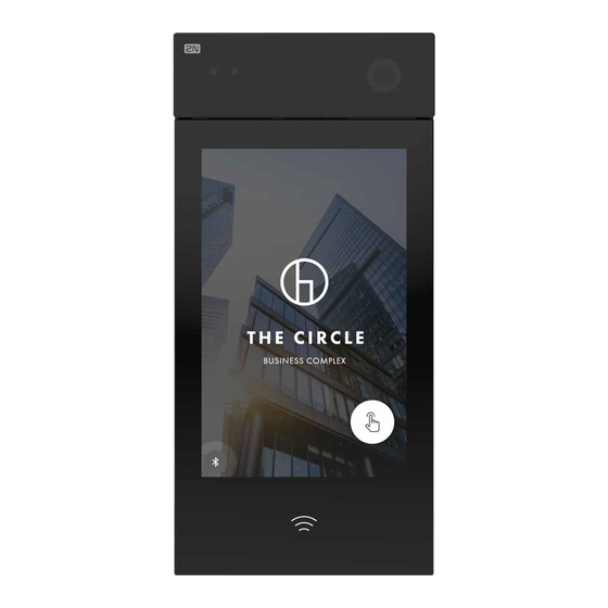
Sleep Mode ® IP Style switches to the Sleep mode after an idle timeout (default value is 60 s). In the Sleep mode, you can go to the Showcase mode to display a presentation or the company logo/address (see Subs. -
Page 76: Calling To Phone Book Position
Calling to Phone Book Position ® ® IP Style displays the group / user name list. The 2N IP Style Phone Book can contain up to 10 000 pre-programmed positions. The group / user list can be displayed as a classic name list or as a set of cards (refer to Subs. -
Page 77: Incoming Call Answering/Rejecting
Door Opening (Switch Activation) by RFID Card ® IP Style is equipped with a door unlocking switch. To activate this switch, tap a valid card or chip on the integrated card reader. Remember to complete the user access card ID (refer to Subs. 5.2.1 Users... -
Page 78: Door Opening (Switch Activation) By Code
Door Opening (Switch Activation) by Code ® IP Style is equipped with a door unlocking switch. Enter the valid code (refer to Subs. 5.3.1 Switchesof the Configuration Manual for IP Intercoms) using the touch numeric keypad to activate this switch. -
Page 79: Intercom Control As Viewed By Internal User
is active, i.e. displayed in the notification bar area, it means that ® the 2N IP Style installation site is secured. It is possible to activate the area security by, e.g., assignment to physical input, via HTTP API, etc. If the green door pictogram is active, it means that the door opening switch is active. -
Page 80: Maintenance
The manufacturer reserves the right to modify the product in order to improve its qualities. ® • IP Style contains no environmentally harmful components. When the product's service life is exhausted, dispose of the product in accordance with applicable legal regulations. 80 / 90... -
Page 81: Downloads
Installation Manual 2N® IP Style 3.5 Downloads Software ® USB driver ® IP Eye ® Network Scanner 81 / 90... -
Page 82: Technical Parameters
Installation Manual 2N® IP Style 4. Technical Parameters Signaling protocol • SIP (UDP, TCP, TLS) Audio • Microphone: 2 integrated microphones • Amplifier: 2 x 4 W (class D) amplifier • Speaker: 2 x 4 W / 4 Ω • Sound pressure level (SPL max): 85 dB (for 1 kHz, distance 1 m) •... - Page 83 Installation Manual 2N® IP Style Bandwidth • Audio codecs • PCMA, PCMU – 64 kbps (with 85.6 kbps headers) • G.729 – 16 kbps (with 29.6 kbps headers) • G.722 – 64 kbps (with 85.6 kbps headers) • L16 / 16 kHz – 256 kbps (with 277.6 kbps headers) •...
- Page 84 Installation Manual 2N® IP Style RFID card reader • Supported 125 kHz cards • EM4xxx • Supported cards in 13.56 MHz NFC version (only card ID is read) • ISO14443A (MIFARE DESFire) • PicoPass (HID iClass) • FeliCa • ST SR(IX) ®...
- Page 85 Installation Manual 2N® IP Style Mechanical properties • Cover: Hardened glass • Body: EN-AW6060 • Surfacing: Wet coating • • Body – RAL 7021 dark grey • Chassis – RAL 7043 • Operating temperature: −30 °C to 60 °C • Working relative humidity: 10 % – 95 % (non-condensing) •...
-
Page 86: Supplementary Information
5.1 Troubleshooting For the most frequently asked questions refer to faq.2n.cz. 5.2 Directives, Laws and Regulations ® IP Style conforms to the following directives and regulations: • 2014/35/EU for electrical equipment designed for use within certain voltage limits • 2014/30/EU for electromagnetic compatibility •... -
Page 87: Other Countries Legislation
Installation Manual 2N® IP Style Changes or modifications to this unit not expressly approved by the party responsible for compliance could void the user's authority to operate this equipment. 5.3 Other Countries Legislation Thailand 本製品は、特定無線設備の技術基準適合証明 を受けていま Japan す。 この装置は、クラスB機器です。この装置は、住宅環境で使 ⽤することを⽬的としていますが、この装置がラジオやテ... -
Page 88: General Instructions And Cautions
Installation Manual 2N® IP Style 5.4 General Instructions and Cautions Please read this User Manual carefully before using the product. Follow all instructions and recommendations included herein. Any use of the product that is in contradiction with the instructions provided herein may result in malfunction, damage or destruction of the product. - Page 89 Installation Manual 2N® IP Style Electric Waste and Used Battery Pack Handling Do not place used electric devices and battery packs into municipal waste containers. An undue disposal thereof might impair the environment! Deliver your expired electric appliances and battery packs removed from them to dedicated dumpsites or containers or give them back to the dealer or manufacturer for environmental- friendly disposal.
- Page 90 Installation manual 2N® IP Style 90 / 90...
Need help?
Do you have a question about the IP Style and is the answer not in the manual?
Questions and answers