Table of Contents
Advertisement
Quick Links
Advertisement
Table of Contents

Related Manuals for 2N SingleTalk


Summary of Contents for 2N SingleTalk
-
Page 1: User Manual
® SingleTalk Lift Communicator User Manual www.2n.cz Version 6.3.0... - Page 2 SingleTalk product complies with all basic requirements and other relevant provisions of the 1999/5/EC directive. For the full wording of the Declaration of Conformity see the CD-ROM enclosed and at www.2n.cz. 2N TELEKOMUNIKACE company is the owner of the ISO 9001:2008 certificate. All...
-
Page 3: Table Of Contents
Product Description ....................... 6 Basic Features ........................6 Advantages of use ......................6 ® SingleTalk Components and Associated Products ..........8 Basic Unit – Universal version ..................8 Basic Unit – Compact Version ..................10 Changes ........................12 Terms and Symbols Used ................... 13 Manual Symbols ...................... - Page 4 GSM Gateway Connection ..................... 42 PBX Connection ......................43 ® 3. Configuration 2N SingleTalk ......... 45 ® SingleTalk Programming ..................46 Before You Start Programming ..................46 Entering Programming Mode ..................46 Programming ........................46 Programming Error ......................47 Programming Termination ....................47 How to Record a Message .....................
- Page 5 Switch Parameters ......................66 Other Parameters ......................67 6. Supplementary Information ..........69 Regulations and directives ..................70 List of Terms and Abbreviations ................71...
-
Page 6: Product Overview
Product Overview ® In this section, we introduce the 2N SingleTalk product, outline its application options and highlight the advantages following from its use. Here is what you can find in this section: Product Description ® SingleTalk Components and Associated Products ... -
Page 7: Product Description
Product Description 1.1 Product Description Basic Features The SingleTalk (ST) is intended primarily for lifts – especially in buildings, where there is just one lift and no internal communication between the lift car ® and the machine room/shaft bottom/lift car roof is needed (2N LiftNet is designed for more complex applications). - Page 8 Product Description Optional indication elements – backlit pictograms (incl. incandescent lamps)
-
Page 9: Singletalk Components And Associated Products
2N® SingleTalk Components and Associated Products ® 1.2 2N SingleTalk Components and Associated Products Basic Unit – Universal version These units are designed for mounting behind the lift panel, which is pre-drilled for installation. Part No., Name Description successor to 913401 913640E ... - Page 10 2N® SingleTalk Components and Associated Products Extending modules for Basic Unit 91364x Part No., Name Description 913647E Enables to record and reproduce messages ® SingleTalk – Extends automatic dialling up to 6 numbers Extending Module 913648E DTMF remote controlled universal switch (during ®...
-
Page 11: Basic Unit - Compact Version
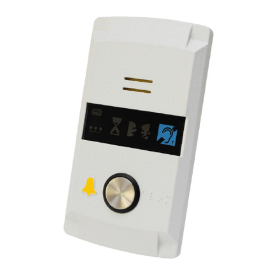
2N® SingleTalk Components and Associated Products Basic Unit – Compact Version The Compact communicator is designed for quick and easy installation into any lift without advance preparation. Order No., Name Description 913644E no user-defined message recording ® Single Talk by phone, no... - Page 12 PCs. ® Note: Service Tools, a software for 2N SingleTalk configuring, upgrading etc. ® via PC, is a free and can be installed separately, without 2N LiftManager. 5013331E ® EasyGate Pro GSM gateway for ®...
-
Page 13: Changes
Changes 1.3 Changes Manual Changes Version First versions of the product and User Manual Functional replacement of the 91340..series (Lift EasyTalk) Addition of the Compact version. Changed default values of parameters 902 and 915 On-board microphone (apart from custom versions) ... -
Page 14: Terms And Symbols Used
Terms and Symbols Used 1.4 Terms and Symbols Used Manual Symbols Safety Always abide by this information to prevent persons from injury. Warning Always abide by this information to prevent damage to the device. Caution Important information for system functionality. ... -
Page 16: Description And Installation
Description and Installation ® This section describes the 2N SingleTalk product and its installation. Here is what you can find in this section: Product Description Before You Start Mounting – Universal version Mounting – Compact version ... -
Page 17: Product Description
2.1 Product Description ® In principle, 2N SingleTalk (hereinafter referred to as ST) is a Speakerphone. It is equipped with a microphone, loudspeaker, telephone line terminals, ALARM buttons, backlit pictograms (as required by the applicable standard) and an optional CANCEL input for door opening indication. - Page 18 Product Description...
-
Page 19: Before You Start
The loudspeaker and microphone (in client-designed versions, the second microphone can be connected by cable); ® CD with a full manual, Service Tools and 2N LiftManager This brief manual and a warranty certificate Product Completeness Check – Compact version... -
Page 20: St Installation Conditions
Before You Start ST Installation Conditions ST is not designed for outdoor applications. The product is connected to a telephone line where life-endangering voltage may occur. Therefore, be sure to keep the safety precautions – refer to the Electric Installation section. -
Page 21: Mounting - Universal Version
Mounting – Universal version 2.3 Mounting – Universal version Safety Precaution Safety The telephone line supply cable, microphone, loudspeaker, LED indicators, ALARM button and CANCEL contact, including cabling, and the board with electronics are connected with a telephone line and so remember to ensure during installation that the user cannot touch these product parts and is protected against an electrical accident by a minimum isolation distance of 1.5 mm, or an isolation barrier of a minimum break-down... -
Page 22: Mounting Of Panel With St Electronics
Mounting – Universal version Mounting of Panel with ST Electronics To mount the ST panel onto the lift car interior wall surface you need 4 spot-welded M4 screws in the pitch of 57×122 mm and a sufficiently perforated loudspeaker area (may be larger than as shown on the figure, yet in no case may overlap the panel size to avoid acoustic short-circuit), a microphone hole and 2 LED holes if necessary. - Page 23 Mounting – Universal version Mounting drawing for version with 40 mm speaker 4 spot-welded M4 screws on the panel or lift cabin backside (typically 2 mm thick stainless steel sheet) perforated loudspeaker area (25% perforation at least) Two LED holes (optional, backlit pictograms are preferred, located outside the panel) Microphone perforation...
-
Page 24: Off-Panel Microphone Mounting
Mounting – Universal version Off-Panel Microphone Mounting By default, the microphone is placed directly on board (see drawing for microphone position). If required, a cable-equipped microphone is available, fitted to a holder of the size of 25×25 mm with self-adhesive foil. This helps mount the microphone behind any hole in the wall surface (a hole with the minimum diameter of 3 mm, or a group of smaller holes of the same total area). -
Page 25: Indicator Mounting
Mounting – Universal version Indicator Mounting You can choose any of the following three ST status indication options: Use the backlit pictograms integrated in the lift cabin control panel. Add optional light guides to the existing ST LEDs to conduct light to two panel holes. -
Page 26: Mounting - Compact Version
Mounting – Compact version 2.4 Mounting – Compact version Safety Installing the telephone line cable, ensure that the user cannot touch the conductors and is protected against an electrical accident by a minimum isolation distance of 1.5 mm, or an isolation barrier of a minimum break- -down voltage of 1,500. -
Page 27: Installation - Universal Version
Installation – universal version 2.5 Installation – universal version Layout of Terminals, Jumpers and Connectors Amplifier module Layout of Terminals (optional) power terminal Telephone line lift blocking contact (where the blocking module is ALARM terminal placed) – voltage control switch 2 contact ALARM terminal (where a switch is –... - Page 28 Installation – universal version Jumper Settings Left-hand jumper (ALARM INPUT) Right-hand jumper (PROGRAMMING) inverted ALARM input disabled PROGRAMMING closing contact or voltage enabled (NORMAL) connection activation (ENABLED) down breaking contact or voltage down disabled (NEG.) disconnection activation (DISABLED) Connectors accessible after cover removal servicing connector (button 2 can be connected to two...
-
Page 29: Description Of Terminals
Installation – universal version Description of terminals Polarity does not matter. Can be connected directly to a private telephone network (PSTN), PBX or GSM gateway line. Telephone line CAUTION – more than one unit may not be connected to a single line!!! voltage control 12 –... -
Page 30: St Telephone Line Connection
Installation – universal version ST Telephone Line Connection The ST works regardless of polarity or line parameters in a wide range (see Technical Parameters). The line is connected to the LINE terminals. A great advantage of the ST is that it needs no other power supply for its operation. Details on the ST connection to PSTN, PBX and GSM gateway lines are available in the "ST Connecting Options”... -
Page 31: Indicator Connection
Installation – universal version Indicator Connection Basic connection In this type of connection, any indication elements can be used (backlit pictograms, e.g.). An external power supply provides a sufficient indicator intensity. Requirements a 12 – 24 V power supply (backed ... -
Page 32: Cancel Input Connection (Door Control, Optional)
Installation – universal version CANCEL Input Connection (Door Control, Optional) Caution The door switch or door opening signal must indicate an open door only if both the internal and external lift doors are open and the lift car can be left safely. -
Page 33: Induction Loop Connection
Installation – universal version Induction Loop Connection The regulations that apply to communicator installations may require a mandatory loop for persons with defective hearing in the lift cabin. In that case, connect the loop to the connector with any polarity as shown in the drawing. The loop including a 1 m long cable can be part of the delivery if agreed so in advance. - Page 34 Installation – universal version Switch Installation Universal switch module (order No. 913648E) can be installed (before ST mounting!) into position 1 or 2 without removing the ST cover. Having inserted the module into the motherboard margin slots, tighten the two screws (through the panel cutouts). Caution Be sure to tighten both the screws! ...
- Page 35 Installation – universal version Extending module Installation The extending module (Part No. 913647E) allows you to record and play your own voice messages (the lift cabin address, e.g.). Typically, it is integrated in ST as Part No. 913641 or 913643. But it can also be mounted additionally as described below. Note Before installing an extending module produced earlier, check it for ...
-
Page 36: Installation - Compact Version
Installation – Compact Version 2.6 Installation – Compact Version Caution Be sure to connect the wires before wall mounting. The connectors are separable – remove them, connect the wires, tighten the screws and replace the connectors. Safety Precautions The product is connected to a telephone line where life-endangering ... -
Page 37: Terminal Description (Newer Hw)
Installation – Compact Version Terminal Description (newer HW) The above mentioned safety precautions need not be observed in case your ST unit is connected to a 2N® EasyGate GSM gateway installed near the communicator. Terminals Telephone line / LN bus... - Page 38 Installation – Compact Version ALARM Button Connection with N/O Contact ALARM Button Connection with N/C Contact Notes The ALARM button mounted on the cover is still functional when an external button is connected.
- Page 39 Installation – Compact Version Voltage Activation Notes 5 - 24 dc voltage of any polarity can be used. Make sure that the power supply is backed up properly. Where activation from multiple places is necessary, voltage control can be ...
-
Page 40: Telephone Line Connection
Installation – Compact Version Warning It is impossible to connect multiple devices to a single line!!! The Compact version is very easy to install because the ALARM button, backlit picrograms and induction loop are part of the product. All you have to do is connect a telephone line. -
Page 41: Mounting Completion
Installation – Compact Version product, located to the right in the window area and labelled with the prescribed blue pictogram. Mounting Completion Having connected the wires, you can complete the ST wall mounting. The mounting is easier if you can access the cabin wall from the outside. In this case, the screws are inaccessible from the cabin and ST cannot be stolen. - Page 42 Installation – Compact Version Mounting Completion – withour rear access 1. Insert the hex wrench (included in the delivery) in the bottom unit edge hole; turn left about 10 times until it puts up resistance. 2. The window slides down by itself or with little assistance, showing its upper brim.
-
Page 43: St Connecting Options
ST Connecting Options 2.7 ST Connecting Options Direct PSTN Connection Advantages and disadvantages This is the most reliable and simplest connecting option. The costs include acquisition costs plus a line installation fee, yet the ST operation is relatively cheap (monthly fee). -
Page 44: Pbx Connection
ST Connecting Options Choose the optimum location for your antenna. Use an external directional antenna for places with a bad signal quality. Ensure that your GSM gateway function will go on working upon power failure without the need to enter the PIN. Safeguard the GSM gateway SIM card against misappropriation. -
Page 46: Configuration 2N ® Singletalk
Configuration ® SingleTalk ® This section describes configuration of the product 2N SingleTalk Here is what you can find in the section: ® SingleTalk Programming Review of Programming Functions ... -
Page 47: Singletalk Programming
2N® SingleTalk Programming ® 3.1 2N SingleTalk Programming Before You Start Programming Make sure that programming is not restricted (PROGRAMMING jumper) and that your telephone supports tone dialing. Use the pre-prepared form, which is also a clear table of basic functions, and ... -
Page 48: Programming Error
2N® SingleTalk Programming To check programmed values: enter parameter number and , listen the parameter value and press for return to the main menu. Caution Unfortunately, some telephone sets become “mute” for a second after sending the DTMF signal. Try to use another telephone in this case. -
Page 49: How To Record A Message
2N® SingleTalk Programming How to Record a Message (for models 913641, 913643 and 913645, or 913640 and 913642 with extending module 913647 only) A message can only be recorded in the programming mode (see the respective chapter) and if the voice recording module is present. It is protected with a password and, optionally, with a programming barring jumper. -
Page 50: Setting Acoustic Parameters
2N® SingleTalk Programming Setting Acoustic Parameters The ST automatic handsfree mode works as follows: if there is silence on both sides, the sound channel is muted; if a threshold sound level is exceeded, the loudspeaker or the microphone goes on depending on which party starts talking, or is talking more loudly. -
Page 51: Communication Equipment - Abbrev. Programming Form
2N® SingleTalk Programming Communication Equipment – Abbrev. Programming Form Function Number and Name Value Range Initializa- Value Programmed Notes, Explanations tion Value by You To delete the memory, enter a “zero 011 – ALARM button memory 1 up to 16 digits empty length number“, e.g. - Page 52 2N® SingleTalk Programming Function Number and Name Value Range Initializa- Value Programmed Notes, Explanations tion Value by You 5–99 915 – hang-up timeout corresponds to 40 = 4 s between calls 0.5 to 9.9 s 0 = contact closed (or voltage present) at open door 916 –...
-
Page 53: Review Of Programming Functions
Review of Programming Functions 3.2 Review of Programming Functions Function Value Range Initializa- Notes, Explanations Number and Name tion Value To delete the memory enter a “zero length number“, e.g. 0 1 1 * * ALARM button memories up to 16 digits Empty Digits may be entered only. - Page 54 Review of Programming Functions Function Value Range Initializa- Notes, Explanations Number and Name tion Value Adds another password to the list. The password may not be identical with any other password; Switch 1,2,3 password up to 16 digits otherwise it is rejected. Password 00 may not be addition entered from a keyboard.
- Page 55 Review of Programming Functions Function Value Range Initializa- Notes, Explanations Number and Name tion Value 931 – microphone trigger level 0 = maximum microphone 0–3 sensitivity 932 – automatic response 3 = maximum response 0–3 speed speed 933 – receiving volume 15 = maximum receiving 0–15 volume...
- Page 56 Review of Programming Functions Function Value Range Initializa- Notes, Explanations Number and Name tion Value 1 = 0.1 s 962 – minimum button pressing 01–99 Applies to all buttons. change time 0 – disabled 963 – hang-up option with the The calling party may not terminate the call same button according to applicable regulations.
- Page 57 Review of Programming Functions Function Value Range Initializa- Notes, Explanations Number and Name tion Value 0 = off 1 = checking call in 1 minute; if previously off, the checking call is enabled and the 3-day period initialization is executed. 0 –...
-
Page 58: Function And Use
Function and This section describes the basic and extending functions of the product. Here is what you can find in the section: Function Description Non-Stop Service Instructions for Use ... -
Page 59: Function Description
“Checking call“, and a different set of numbers may be used. Checking calls are typically received automatically – in case the dispatcher‘s centre is ® equipped with the 2N LiftManager software. A standard PC with an analog modem can be used for running the program. -
Page 60: Automatic Repeated Multiple Numbers Dialing With Confirmation
(maximum call time). ST sends identification but the connection is not confirmed. DTMF sign ® Used for 2N LiftManager applications. These digits are interpreted as control characters (refer to... -
Page 61: Automatic Repeated Multiple Numbers Dialing Without Confirmation
Function Description Section 3.6). Caution The quality of PSTN connection does not always allow for a reliable recognition of all the situations mentioned above. Any excessive noise in the lift car can have a negative impact too, slowing down, yet never discontinuing, automatic dialing (the busy tone is not detected). -
Page 62: Call Termination (Outgoing And Incoming Calls)
Function Description The ST waits for a defined timeout (logon time), Talk or silence then hangs up and dials the following number The ST hangs up in approximately 2 seconds and Continuous tone (PBX) dials the following number Ringing tone is terminated before This is considered as a successful call, the call 10 rings (or as programmed) are continues for the defined period of time (maximum call... -
Page 63: Non-Stop Service Instructions For Use
1 to 5 are arranged in the order they are usually used in. DTMF CHAR FUNCTION DESCRIPTION It is a confirmation notifying SingleTalk (hereinafter referred to as ST) that the call was successful. ST mutes the message playback, sends out the confirmation signal and the call continues until the end of the timeout and the following commands can be used Message playback muting. -
Page 64: St Signalling Overview
Non-Stop Service Instructions for Use turns it on for the pre-defined period of time (1 to 10 seconds). It is not possible to talk during the switch on-status and the ST signals this action with tones as per the signaling review table. The call is terminated 30 seconds after the switch activation. The switch can be used, for example, for resetting the lift Each switch can ... -
Page 65: Survey Of Messages
Non-Stop Service Instructions for Use Survey of Messages The table below includes a survey of language versions for standard announcements. English is selected by default. To select another language use parameters 976 and 977. Outgoing call message Language Value of selection –... -
Page 66: Technical Parameters
Technical parameters This section describes the technical parameters of the product. -
Page 67: Technical Parameters
Technical parameters 5.1 Technical parameters Electric Parameters Parameter Value Conditions Minimal off-hook line current 15 mA Off-hook Minimal on-hook line voltage 22 V Off-hook DC voltage drop (off-hook) I = 25 mA < 8 V < 16 V I = 50 mA Off-hook resistance >1MΩ... -
Page 68: Other Parameters
Technical parameters Other Parameters Universal dimensions 65×130×24 mm Compact dimensions 100×185×16 mm Working temperature range -20 to +70 ˚C... -
Page 70: Supplementary Information
Supplementary Information This section describes supplementary information of the product. Here is what you can find in this section: Regulations and directives Chyba! Nenalezen zdroj odkazů. List of Terms and Abbreviations ... -
Page 71: Regulations And Directives
Regulations and directives 6.1 Regulations and directives ® SingleTalk conforms to the following directives and regulations: Directive 95/16/EC of the European Parliament and of the Council, of 29 June 1995 on the approximation of the laws of the Member States relating to lifts Directive 1999/5/EC of the European Parliament and of the Council, of 9 ... -
Page 72: List Of Terms And Abbreviations
There may be separate workplaces, each for one type of calls, even mobile ones. LM, LiftManager 2N TELEKOMUNIKACE dispatcher software A private branch exchange (equipped with a PSTN line and local analog lines) PSTN The public switched telephone network. It is assumed for simplification that ST is connected to the PSTN although it works on a PBX line in the same way. - Page 73 2N TELEKOMUNIKACE a.s. Modřanská 621, 143 01 Prague 4, Czech Republic Tel.: +420 261 301 500, Fax: +420 261 301 599 E-mail: sales@2n.cz Web: www.2n.cz DR1514 v6.3.0...
Need help?
Do you have a question about the SingleTalk and is the answer not in the manual?
Questions and answers