Advertisement
Advertisement
Table of Contents

Subscribe to Our Youtube Channel
Related Manuals for Yardworks 060-1314-4


Summary of Contents for Yardworks 060-1314-4
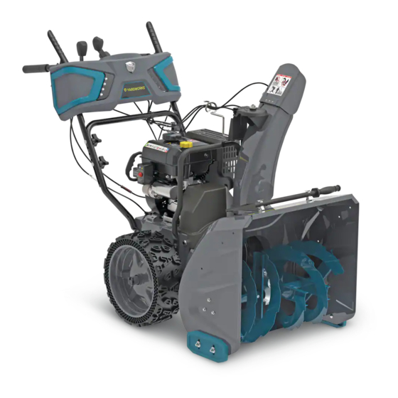
- Page 1 Snowblower model number 060-1314-4 | contact us: 1.866.523.5218 IMPORTANT: Please read this manual carefully before operating this snowblower and save it for reference. WARNING: Machine is without engine oil. Properly fill engine oil prior to use to prevent engine damage.
-
Page 2: Table Of Contents
TAble Of CONTeNTS model no. | contact us: 1.866.523.5218 060-1314-4 TABLE OF CONTENTS SAFETY INSTRUCTIONS SAFETY SYMBOLS OPERATION SYMBOLS SPECIFICATIONS ASSEMBLY OPERATION STARTING THE ENGINE CONTROLS MAINTENANCE TROUBLESHOOTING WARRANTY For problems or questions, DO NOT ReTURN TO STORe. Please contact one of our Customer Service Agents who would be happy to assist you. -
Page 3: Safety Instructions
| contact us: 1.866.523.5218 060-1314-4 SAfeTy DefINITIONS allow adults to operate the equipment without proper instruction. The purpose of safety symbols is to attract your attention to possible dangers. The Thrown objects can cause serious – safety symbols, and their explanations, injury. - Page 4 | contact us: 1.866.523.5218 060-1314-4 Let engine and machine adjust to Do not over fill fuel tank. Keep fuel – – outdoor temperatures before starting to level at least ½" (1.27 cm) below clear snow. bottom of filler neck to provide space for fuel expansion.
- Page 5 | contact us: 1.866.523.5218 060-1314-4 OPeRATION Do not clear snow across the face of – slopes. Exercise extreme caution when Do not put hands or feet near or – changing direction on slopes. Do not under rotating parts. Keep clear of the attempt to clear steep slopes.
- Page 6 | contact us: 1.866.523.5218 | contact us: 1.866.523.5218 060-1314-4 060-1314-4 Replace worn or damaged parts for To clear the chute: – safety. Use only genuine replacement SHUT THE ENGINE OFF! – parts and accessories. Wait 10 seconds to be sure the –...
-
Page 7: Safety Symbols
| contact us: 1.866.523.5218 060-1314-4 Some of the following symbols may be used on this product. Please study them and learn their meaning. Proper interpretation of these symbols will allow you to more safely operate the product. Symbol Meaning Read Operator’s Manual. - Page 8 | contact us: 1.866.523.5218 | contact us: 1.866.523.5218 060-1314-4 060-1314-4 Symbol Meaning Thrown Objects. This machine may pick up and throw objects which can cause serious personal injury. Always Use Chute Tool. Never use your hands to clear a clogged chute assembly.
-
Page 9: Operation Symbols
OPeRATION SyMbOlS model no. | contact us: 1.866.523.5218 060-1314-4 Some of the following symbols may be used on this product. Please study them and learn their meaning. Proper interpretation of these symbols will allow you to more safely operate the product. - Page 10 | contact us: 1.866.523.5218 | contact us: 1.866.523.5218 060-1314-4 060-1314-4 Symbol Meaning Warm Prime. To start a warm engine, DO NOT prime. Recoil Start. Pull the recoil starter grip to start manually. Choke: Off. When the engine starts, move the choke to run position.
-
Page 11: Specifications
| contact us: 1.866.523.5218 060-1314-4 SNOWblOWeR Stages Speed Control 6 forward/2 reverse Clearing Width 24" (61 cm) Clearing Depth 23" (58.4 cm) Impeller Diameter 12" (30.5 cm) Wheel Diameter 15" (38 cm) 14" (35.6 cm) Auger Diameter eNGINe... - Page 12 | contact us: 1.866.523.5218 060-1314-4 SNOWblOWeR eNGINe A. Discharge Chute Rotation Lever A. Key (Safety Lock Out) B. Auger Control Lever B. Primer Bulb C. Speed Control Lever C. Throttle Lever D. Shear Pin Storage D. Choke Lever E.
- Page 13 | contact us: 1.866.523.5218 060-1314-4...
-
Page 14: Assembly
ASSeMbly model no. model no. | contact us: 1.866.523.5218 | contact us: 1.866.523.5218 060-1314-4 060-1314-4 UNPACKING 1. Set the shipping carton on a solid, flat surface. 2. Remove everything loose from the carton. 3. Cut down the bottom carton to allow a flat surface area to install the assembly parts without scratching parts or cutting tires. - Page 15 | contact us: 1.866.523.5218 060-1314-4 HANDle 1. Attach the lower handle (1-1) onto the unit body with 4 self-tapping bolts (1-2) using included tool or your own 13mm wrench (Fig. 1). Figure 1 2. Connect the upper and lower handle with bolts (2-1), washers (2-2) and locking knobs (2-3) (Fig.
- Page 16 | contact us: 1.866.523.5218 060-1314-4 4. Put the snow discharge chute cable wire form on the snow discharge support using the washer (4-1) and nut (4-2). Securely tighten the assembly (Fig. 4) using included tool or your own 16mm wrench.
- Page 17 | contact us: 1.866.523.5218 060-1314-4 CHeCK/ADD eNGINe OIl Recommended Engine Oil Type Capacity of engine oil: 16.9 fl. oz. (0.5 l) Use 0W-30, but in some cases, depending 0W-30 5W-30 on weather, 5W-30 will work. See chart for oil type recommendations.
- Page 18 | contact us: 1.866.523.5218 060-1314-4 ADD fUel fuel tank capacity: 0.7 gal. (2.6 l) Use clean, fresh, regular unleaded gasoline with a minimum octane rating of 87 and an ethanol content of less than 10% by volume. SAfe HANDlING Of GASOlINe To avoid severe injury or property damage use high levels of care while handling gasoline.
- Page 19 | contact us: 1.866.523.5218 060-1314-4 12. If possible, remove gas-powered equipment from the truck or trailer and refuel it on the ground. If this is not possible, then refuel such equipment on a trailer with a portable container, rather than from a gasoline dispenser nozzle.
-
Page 20: Operation
| contact us: 1.866.523.5218 | contact us: 1.866.523.5218 060-1314-4 060-1314-4 GeNeRAl SAfeTy 1. Read the operating and service instruction manual carefully. Be thoroughly familiar with the controls and the proper use of the equipment. Know how to stop the unit and disengage the controls quickly. - Page 21 | contact us: 1.866.523.5218 060-1314-4 OPeRATION 1. Do not put hands or feet near or under rotating parts. Keep clear of the discharge opening at all times. 2. Exercise extreme caution when operating on or crossing gravel drives, walks, or roads.
- Page 22 | contact us: 1.866.523.5218 060-1314-4 18. Take all possible precautions when leaving the machine unattended. Stop the engine and remove the safety key. 19. Keep all nuts, bolts and screws tight to be sure the equipment is in safe working condition.
- Page 23 | contact us: 1.866.523.5218 060-1314-4 befORe OPeRATION CHeCK THe GeNeRAl CONDITION: Look around and underneath the engine for signs of oil or gasoline leaks. – Remove any excessive dirt or debris, especially around the muffler and recoil starter.
-
Page 24: Starting The Engine
STARTING THe eNGINe model no. model no. | contact us: 1.866.523.5218 | contact us: 1.866.523.5218 060-1314-4 060-1314-4 1. Make sure the engine key (safety lock out) is inserted into the keyhole. 2. To start a cold engine: (Fig. 11). 2a. Move the throttle lever (11-1) to full speed. - Page 25 | contact us: 1.866.523.5218 060-1314-4 4. Stand back and to the right of the unit, pull the starter grip lightly until you feel resistance then pull briskly. Return the starter grip gently (Fig. 13). Figure 13 5. Alternatively, for electric start, plug in the supplied electrical cord into the starter.
- Page 26 | contact us: 1.866.523.5218 | contact us: 1.866.523.5218 060-1314-4 060-1314-4 OPeRATION AT HIGH AlTITUDe The density of air at high altitude is lower than at sea level. Engine power is reduced as the air mass and air-fuel ratio decrease. Engine power will be reduced approximately 3 ½% for every 1000' (304 m) of elevation above sea level.
-
Page 27: Controls
CONTROlS model no. | contact us: 1.866.523.5218 060-1314-4 Self-DRIVe CONTROl leVeR. Located on the left-side (from behind the snowblower). When the snowblower has been put into gear, pushing this lever towards the handle engages the wheels. Releasing the self-drive control lever causes the machine to stop moving. - Page 28 | contact us: 1.866.523.5218 060-1314-4 AUGeR CONTROl leVeR. Located on the right side (from behind the snowblower). Pushing this lever towards the handle causes the auger and impeller to activate. Releasing the auger control lever causes the auger to stop moving.
- Page 29 | contact us: 1.866.523.5218 060-1314-4 ADJUSTING THe Self-PROPelleD DRIVe SySTeM: 1. Release the self-drive control lever to bring the snowblower to a stop. 2. Move the speed-control lever to the gear (either forward or reverse) that you require.
- Page 30 | contact us: 1.866.523.5218 | contact us: 1.866.523.5218 060-1314-4 060-1314-4 CHANGe DISCHARGe DIReCTION: 1. Move the discharge chute rotation lever either left or right. CHANGe DISCHARGe HeIGHT: 1. Discharge chute deflector lever controls the deflector up or down.
-
Page 31: Maintenance
MAINTeNANCe model no. | contact us: 1.866.523.5218 060-1314-4 OIl CHANGe Drain the engine oil when the engine is warm. Warm oil drains quickly and completely. 1. Turn the fuel valve lever to the OFF position to reduce the possibility of fuel spillage. - Page 32 | contact us: 1.866.523.5218 060-1314-4 RePlACING SHeAR PINS 1. The augers are secured to the spiral shaft with shear pins and clips. If the auger should strike a foreign object or ice jam, the snowblower is designed so that the pins shear.
- Page 33 | contact us: 1.866.523.5218 060-1314-4 Scan this QR code for video walkthroughs on the various cable adjustments. ADJUSTING Self-DRIVe CONTROl HANDle CAble The cables are preset by the factory. Proper tension is important because you will want your snowblower to move forward properly in heavy snowfalls.
- Page 34 | contact us: 1.866.523.5218 060-1314-4 Tighten the cable and reduce the length of stage 1 to approximately what is shown above visually. Do not reduce the length of stage 1 to almost none, there will be a risk of no disengagement.
- Page 35 | contact us: 1.866.523.5218 060-1314-4 ADJUSTING Self-DRIVe SPeeD CONTROl HANDle CAbleS 1. Make sure all fluids are removed and spark plug is disconnected. 2. Locate the speed control cables. There are 2 cables. 3. Move the speed control lever to the fastest (top) and slowest (bottom) position.
- Page 36 | contact us: 1.866.523.5218 060-1314-4 4. If you are able to adjust the speed lever to top most or bottom most position, move the lever to rest on the boss between R1 and R2 (both reverse speeds), then adjust the center bolt and nut until the cable is tight on the top most cable as shown.
- Page 37 | contact us: 1.866.523.5218 060-1314-4 8. A slow speed of D1 (slowest forward speed) will be helpful for thick snow. If you want to decrease D1 speed, loosen about 1 or 2 threads for cable 1, then tighten about 1 or 2 threads for...
- Page 38 | contact us: 1.866.523.5218 060-1314-4 2. Locate and adjust the bolt and nut on the cable. Lengthening this nut connection will create more tension with the auger belt. Do not over adjust the cable, too much tension on belt will not allow the belt to separate from the pulley when disengaging.
- Page 39 | contact us: 1.866.523.5218 060-1314-4 1. Adjust the right cable to increase turn to max. Tighten 2. Adjust the left cable to increase turn to max. Loosen the nut counterclockwise, then loosen the center bolt clockwise. Tighten Test function. Tighten the nut clockwise against the long sleeve bolt.
- Page 40 | contact us: 1.866.523.5218 060-1314-4 2. Remove the B pin. 3. Remove the anchor pin by sliding it off. 4. On the control panel side, press the cable busing tabs and pull it out. Be careful not to damage the tabs.
- Page 41 | contact us: 1.866.523.5218 060-1314-4 5. On the chute side, press the cable busing tabs and pull it out. Be careful not to damage the tabs. 6. Remove the cable end from the bracket. 7. Follow the reverse steps to replace the cable.
- Page 42 | contact us: 1.866.523.5218 060-1314-4 RePlACe Self-DRIVe CONTROl HANDle CAble 1. Carefully pivot the snowblower up and forward so that it rests on the auger housing. Place a piece of cardboard or moving blanket on the ground before tipping forward. Make sure all fluids are removed and spark plug is disconnected.
- Page 43 | contact us: 1.866.523.5218 060-1314-4 6. Unhook the connector in the control handle. You may have to move the control handle to make these easier to remove (3). 7. Squeeze and remove the strain relief from the control handle side (4).
- Page 44 | contact us: 1.866.523.5218 060-1314-4 2. Slip the old auger drive belt over the auger drive pulley. If you are unable to remove the belt in this step, please disassemble the engine pulley in the next step. 3. Remove the engine pulley and washer.
- Page 45 | contact us: 1.866.523.5218 060-1314-4 6. Save the key from each wheel. Do not lose each key from each wheel. You will need this when you put it back together. 7. Remove the base frame cover from the underside of the snowblower by removing the six M6 ×...
- Page 46 | contact us: 1.866.523.5218 060-1314-4 9. Slide the speed adjusting handle to position 6 (fastest forward speed) to move the rubber ring assembly to the edge of the friction disc. Then remove the loose belt by cutting it. If the belt has already broken, then remove any remaining belt pieces.
- Page 47 | contact us: 1.866.523.5218 060-1314-4 12. Reassemble / reattach the base frame cover. 13. Reattach the wheels. Slide the key into the keyway of the axle and align the slot on the wheel hub. 14. Attach the wheel clip until it clicks into...
- Page 48 | contact us: 1.866.523.5218 060-1314-4 15. Turn the snowblower right side up. With the belt properly placed on both the front pulley and the auger drive pulley, pull the auger idler pulley back away from the belt and slip the belt inside the pulley.
- Page 49 | contact us: 1.866.523.5218 060-1314-4 RePAIR OR RePlACe fRICTION DISC Make sure all fluids are removed and spark plug is disconnected. Tools required: 12 size wrench. – 19 size wrench. – To remove and replace your snowblower’s friction disc, proceed as follows: 1.
- Page 50 | contact us: 1.866.523.5218 060-1314-4 5. Carefully remove the M8 hex nut on each side which secures the hex shaft and chain gear shaft to the snowblower frame. Use a 19mm or adjustable wrench to hold the center of the hex shaft and use a 12mm socket to remove the nuts on each side.
- Page 51 | contact us: 1.866.523.5218 060-1314-4 9. Unscrew the three M8 bolts of the friction disc assembly to discard the worn friction wheel rubber ring and replace with a new one. Use 3 new self-locking nuts to assemble a new rubber ring, do not over tighten.
- Page 52 | contact us: 1.866.523.5218 060-1314-4 4. Remove the cotter pin holding the Shift Fork Steering Unit on. 5. Remove the shift fork assembly plate by remove 4x M6x16mm bolts. 6. Remove the shift fork. 7. Reverse the steps to reassemble. If...
- Page 53 | contact us: 1.866.523.5218 060-1314-4 VAlVe CleARANCe If set in summer: (if set at room temperature about 50°F – 86°F (10°C-30°C) intake clearance 0.10~0.15mm (.004”-.006”) exhaust clearance 0.15~0.20mm (.006”-.008”) If set in winter: (if set in cold at < 32°F (0°C) then recommend setting a little tighter at: intake clearance 0.05~0.10mm (.002”-.004”) exhaust clearance 0.10~0.15mm (.004”-.006”)
- Page 54 | contact us: 1.866.523.5218 | contact us: 1.866.523.5218 060-1314-4 060-1314-4 TRANSPORTING If the engine has been running, allow it to cool for at least 15 minutes before loading the machine on the transport vehicle. A hot engine and exhaust system can burn you and can ignite some materials.
-
Page 55: Troubleshooting
TROUbleSHOOTING model no. | contact us: 1.866.523.5218 060-1314-4 PRObleM POSSIble CAUSe ReMeDy Engine flooded. Repeat start attempts with choke OFF. Water in fuel. Drain tank and refill with fresh fuel. Check carefully the start procedure Other. Engine fails to start. -
Page 56: Warranty
060-1314-4 4-yeAR lIMITeD WARRANTy For Four YEARS from the date of purchase within Canada, YARDWORKS CANADA will, at its option, repair or replace for the original purchaser, free of charge, any part or parts found to be defective in material or workmanship. - Page 57 Made in China Imported by Trileaf Distribution Toronto, Canada M4S 2B8 YARDWORKS CANADA will not be liable for incidental or consequential loss or damage.
- Page 58 CHAMPION POWER EQUIPMENT, INC. (CPE) AND UNITED STATES ENVIRONMENT PROTECTION AGENCY (U.S. EPA) EMISSION CONTROL SYSTEM WARRANTY Your Champion Power Equipment (CPE) engine complies with U.S. EPA emissions regulations. YOUR WARRANTY RIGHTS AND OBLIGATIONS: The US EPA and CPE are pleased to explain the Federal Emission Control Systems Warranty on your 2022 small off-road engine (SORE) and engine powered equipment.
- Page 59 EMISSION CONTROL SYSTEM WARRANTY The following are specific provisions relative to your Emission Control System (ECS) Warranty Coverage. APPLICABILITY: This warranty shall apply to 1997 and later model year small off-road engines (SORE). The ECS Warranty Period shall begin on the date the new engine or equipment is delivered to its original, end-use purchaser, and shall continue for 24 consecutive months thereafter.
- Page 60 3i. Any CPE Authorized and approved emission-related replacement part may be used in the performance of any ECS Warranty maintenance or repair and will be provided without charge to the owner. Such use shall not reduce CPE’s warranty obligation. 3j. Unapproved add-on or modified parts may not be used to modify or repair a CPE engine. Such use voids this ECS Warranty and shall be sufficient grounds for disallowing an ECS Warranty claim.
Need help?
Do you have a question about the 060-1314-4 and is the answer not in the manual?
Questions and answers