Advertisement
Advertisement
Table of Contents

Related Manuals for Yardworks 060-0608-2


Summary of Contents for Yardworks 060-0608-2
- Page 1 Snowblower model number 060-0608-2 | contact us: 1.866.523.5218 IMPORTANT: Please read this manual carefully before operating this snowblower and save it for reference. WARNING: Machine is without engine oil. Properly fill engine oil prior to use to prevent engine damage.
-
Page 2: Table Of Contents
TAble Of CONTeNTS model no. | contact us: 1.866.523.5218 060-0608-2 TABLE OF CONTENTS SAFETY INSTRUCTIONS SAFETY SYMBOLS OPERATION SYMBOLS SPECIFICATIONS ASSEMBLY OPERATION CONTROLS MAINTENANCE TROUBLESHOOTING WARRANTY For problems or questions, DO NOT ReTURN TO STORe. Please contact one of our Customer Service Agents who would be happy to assist you. -
Page 3: Safety Instructions
| contact us: 1.866.523.5218 060-0608-2 SAfeTy DefINITIONS GeNeRAl SAfeTy The purpose of safety symbols is to attract 1. Read the operator's manual carefully. your attention to possible dangers. The Be thoroughly familiar with the controls safety symbols, and their explanations, and the proper use of the equipment. - Page 4 | contact us: 1.866.523.5218 060-0608-2 PRePARATION fOR USe 1. Disengage all clutch handles before starting the engine. 2. Do not operate the equipment without wearing adequate winter garments. Wear footwear which will improve footing on slippery surfaces. 3. Adjust the auger housing height to clear gravel or crushed rock surface.
- Page 5 | contact us: 1.866.523.5218 060-0608-2 SAfe HANDlING Of GASOlINe Gasoline is an extremely flammable substance and the vapors are explosive. Serious personal injury can occur when gasoline is spilled on yourself or your clothes, which can ignite. If you come into contact with gasoline, wash affected areas of skin and change clothing immediately.
- Page 6 | contact us: 1.866.523.5218 060-0608-2 OPeRATING THe SNOWblOWeR 1. Do not put hands or feet near or under rotating parts. Keep clear of the discharge opening at all times. 2. Exercise extreme caution when operating on or crossing gravel drives, walks, or roads.
- Page 7 | contact us: 1.866.523.5218 060-0608-2 13. Never operate the machine at high transport speeds on slippery surfaces. Use care when reversing. 14. Never direct discharge at bystanders or allow anyone in front of the unit. 15. Disengage power to the impeller when snowblower is transported or not in use.
- Page 8 | contact us: 1.866.523.5218 | contact us: 1.866.523.5218 060-0608-2 060-0608-2 CleARING A ClOGGeD DISCHARGe CHUTe To clear the chute: SHUT THE ENGINE OFF! – Wait 10 seconds to be sure the impeller blades have stopped rotating.
-
Page 9: Safety Symbols
| contact us: 1.866.523.5218 060-0608-2 Some of the following symbols may be used on this product. Please study them and learn their meaning. Proper interpretation of these symbols will allow you to more safely operate the product. Symbol Meaning Read Operator’s Manual. - Page 10 | contact us: 1.866.523.5218 | contact us: 1.866.523.5218 060-0608-2 060-0608-2 Symbol Meaning Thrown Objects. This machine may pick up and throw objects which can cause serious personal injury. Always Use Chute Tool. Never use your hands to clear a clogged chute assembly.
-
Page 11: Operation Symbols
OPeRATION SyMbOlS model no. | contact us: 1.866.523.5218 060-0608-2 Some of the following symbols may be used on this product. Please study them and learn their meaning. Proper interpretation of these symbols will allow you to more safely operate the product. - Page 12 | contact us: 1.866.523.5218 | contact us: 1.866.523.5218 060-0608-2 060-0608-2 Symbol Meaning Insert engine Key. Make sure the engine safety key is inserted into the key hole. Cold Prime. To start a cold engine, prime 3-5 times.
-
Page 13: Specifications
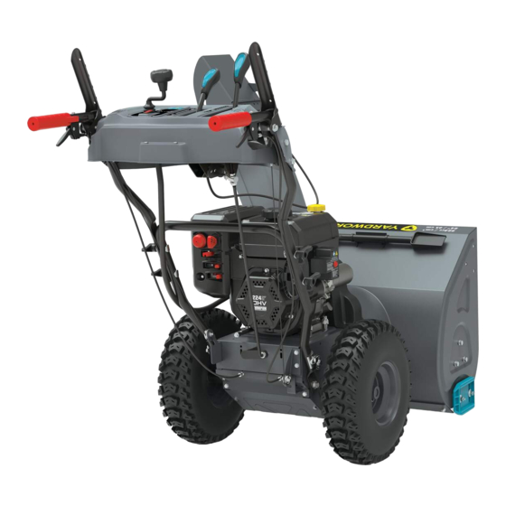
| contact us: 1.866.523.5218 060-0608-2 SNOWblOWeR Stages Speed Control 6 forward/2 reverse Clearing Width 24" (61 cm) Clearing Depth 21" (53.3 cm) Impeller Diameter 12" (30.5 cm) Auger Diameter 12" (30.5 cm) 15" (38 cm) Tire Diameter eNGINe... - Page 14 | contact us: 1.866.523.5218 060-0608-2 SNOWblOWeR eNGINe A. Self -drive Control Lever A. Key (Safety Lock Out) B. Speed Control Lever B. Primer Bulb C. Discharge Chute Deflector Lever C. Throttle Lever D. Shear Pin Storage D. Choke Lever E.
- Page 15 | contact us: 1.866.523.5218 060-0608-2...
-
Page 16: Assembly
ASSeMbly model no. model no. | contact us: 1.866.523.5218 | contact us: 1.866.523.5218 060-0608-2 060-0608-2 UNPACKING 1. Set the shipping carton on a solid, flat surface. 2. Remove everything loose from the carton. 3. Cut down the bottom carton to allow a flat surface area to install the assembly parts without scratching parts or cutting tires. - Page 17 | contact us: 1.866.523.5218 060-0608-2 ASSeMbly PARTS Part Hardware Tool(s) Part Description Hardware Reference Qty. Qty. Needed 13 mm M8 × 20 bolt wrench ø8 Flat Washer Lower 13 mm Handle M8 × 45 bolt wrench Curve washer M8×50 bolt...
- Page 18 | contact us: 1.866.523.5218 060-0608-2 Cross or Steering M5 × 35 screw Phillips-Head Trigger screwdriver Wire (preassembled on engine Harness and panel end) Cable (preassembled) Clamp...
- Page 19 | contact us: 1.866.523.5218 060-0608-2 ReMOVe THe WHeelS To make the lower handle easier to assemble, remove the wheels from both sides. For each wheel, locate the pin (A) holding the wheel on. Lift the ring (B) around the axle (C) and then pull the pin (A) out holding the wheel on (Fig.1).
- Page 20 | contact us: 1.866.523.5218 060-0608-2 2. Connect the upper and lower handle with bolts (F), washers (G) and locking knobs (H) (Fig. 3). Torque until snug. Do not overtighten. Figure 3 INSTAll THe WHeelS Slide the wheel (A) onto axle (B). Tread pattern should face forward. Place axle pin (C) into wheel.
- Page 21 | contact us: 1.866.523.5218 060-0608-2 SPeeD CONTROl CONNeCTING leVeR 1. Attach the connecting lever (A) and connecting base with clip under the panel. Remove the washer and clip, insert as shown into the connecting base, then install the washer (B) and clip (C).
- Page 22 | contact us: 1.866.523.5218 060-0608-2 CHUTe CAble Locate the thick chute cable (A) zip tied to the lower handle and connect under the panel. Make sure this cable is routed underneath the lower handle as shown before assembly to the control panel.
- Page 23 | contact us: 1.866.523.5218 060-0608-2 WIRe HARNeSS Locate engine and panel wire harness. Connect the wire harness by aligning the plug from the panel (A) with the engine harness (B). The harness will make an audible “click.” Press the lock in (the red arrow), then perform a pull test to confirm locked together.
- Page 24 | contact us: 1.866.523.5218 060-0608-2 CAble ClAMPS Connect the cable clamps (A) to the handle bars as shown. If already connected, move into the correct location, and remove to position the cables and then reconnect to the handle bars as shown.
- Page 25 | contact us: 1.866.523.5218 060-0608-2 CHeCK/ADD eNGINe OIl Recommended Engine Oil Type Capacity of engine oil: 16.9 fl. oz. (0.5 L) Use 0W-30, but in some cases, depending 0W-30 5W-30 on weather, 5W-30 will work. See chart for oil type recommendations.
- Page 26 | contact us: 1.866.523.5218 060-0608-2 ADD fUel Fuel tank capacity: 0.7 gal. (2.6 L) Use clean, fresh, regular unleaded gasoline with a minimum octane rating of 87 and an ethanol content of less than 10% by volume. 1. Remove the fuel tank cap (A).
- Page 27 | contact us: 1.866.523.5218 060-0608-2 SAfe HANDlING Of GASOlINe Gasoline is an extremely flammable substance and the vapors are explosive. Serious personal injury can occur when gasoline is spilled on yourself or your clothes, which can ignite. If you come into contact with gasoline, wash affected areas of skin and change clothing immediately.
- Page 28 | contact us: 1.866.523.5218 | contact us: 1.866.523.5218 060-0608-2 060-0608-2 9. Never store the machine or fuel container inside where there is an open flame, spark or pilot light (e.g., furnace, water heater, space heater, clothes dryer etc.).
-
Page 29: Operation
OPeRATION model no. | contact us: 1.866.523.5218 060-0608-2 GeNeRAl SAfeTy 1. Read the operator's manual carefully. Be thoroughly familiar with the controls and the proper use of the equipment. Know how to stop the unit and disengage the controls quickly. - Page 30 | contact us: 1.866.523.5218 060-0608-2 OPeRATING THe SNOWblOWeR 1. Do not put hands or feet near or under rotating parts. Keep clear of the discharge opening at all times. 2. Exercise extreme caution when operating on or crossing gravel drives, walks, or roads.
- Page 31 | contact us: 1.866.523.5218 060-0608-2 17. Never operate the snowblower without good visibility or light. Always be sure of your footing, and keep a firm hold on the handles. Walk; never run. 18. Take all possible precautions when leaving the machine unattended. Stop the engine and remove the safety key.
- Page 32 | contact us: 1.866.523.5218 060-0608-2 befORe OPeRATION CHECK THE GENERAL CONDITION AND MAKE REPAIRS: Look around and underneath the engine for signs of oil or gasoline leaks. – Remove any excessive dirt or debris, especially around the muffler and recoil starter.
- Page 33 | contact us: 1.866.523.5218 060-0608-2 A light coat of wax may be applied to the inside surface of the auger housing, discharge chute and deflector to prevent snow and ice from sticking. Be certain all controls are disengaged, and engine is not running.
- Page 34 | contact us: 1.866.523.5218 060-0608-2 6. Remove snow one auger width beyond street edge by 20-33 feet (6-10 meters) to the snowplow approach side of your driveway entrance. This will give an area for the snowplow exit flow to spill off, which will keep the entrance to your driveway free of a snowplow ridge.
- Page 35 | contact us: 1.866.523.5218 060-0608-2 If snow can only be thrown to one side of the driveway or sidewalk, start at one end on the far side. At the end of the first pass, rotate the discharge chute 180° for the return pass. At the end of each succeeding pass, rotate the discharge chute 180°...
- Page 36 | contact us: 1.866.523.5218 060-0608-2 STARTING THe eNGINe 1. Make sure the engine key (safety lock out) (A) is inserted into the keyhole. FULL SPEED 2. To start a cold engine: (Fig. 20) 2a. Move the throttle lever (B) to full CHOKE speed.
- Page 37 | contact us: 1.866.523.5218 060-0608-2 4. Stand back and to the right of the unit, pull the starter grip lightly until you feel resistance then pull briskly. Return the starter grip gently. (Fig. 22) Figure 22 5. Alternatively, for electric start, plug in the supplied electrical cord into the starter.
-
Page 38: Controls
| contact us: 1.866.523.5218 | contact us: 1.866.523.5218 060-0608-2 060-0608-2 Self-DRIVe CONTROl leVeR Located on the right-side (from behind the snowblower). (Fig. 24) When the snowblower has been put into gear, pushing this lever towards the handle engages the wheels. - Page 39 | contact us: 1.866.523.5218 060-0608-2 AUGeR CONTROl leVeR Located on the left-side (from behind the snowblower). (Fig. 26) Pushing this lever towards the handle causes the auger and impeller to activate. Releasing the auger control lever causes the auger to stop moving.
- Page 40 | contact us: 1.866.523.5218 060-0608-2 DISCHARGe DIReCTION CRANK Move the discharge chute rotation crank either left or right. Clockwise (CW) moves the chute to the right. Counterclockwise (CCW) moves the chute to the left. (Fig. 28) Figure 28 TRIGGeR STeeRING SySTeM This model is equipped with a dual trigger steering feature.
- Page 41 | contact us: 1.866.523.5218 060-0608-2 6. Disengage self-drive control lever (A), then pull both triggers to make a tight 180º turn or push back to the garage. Figure 29 ClUTCH lOCK feATURe This snowblower offers a clutch lock feature that will enable the operator to keep the snowblower moving forward while you adjust the chute.
- Page 42 | contact us: 1.866.523.5218 060-0608-2 This allows the operator to keep driving the snowblower while they now use their left – hand to make any adjustments to the discharge chute needed to maximize operation. To disengage the clutch lock feature simply release the self-drive control lever.
- Page 43 | contact us: 1.866.523.5218 060-0608-2 lIGHTS The lights on the control panel turn on automatically when the engine is started. The lights on the control panel turn off automatically when the engine is stopped.
-
Page 44: Maintenance
MAINTeNANCe model no. model no. | contact us: 1.866.523.5218 | contact us: 1.866.523.5218 060-0608-2 060-0608-2 ADJUST THe SKID SHOeS Tilt the snowblower auger back and place a spacer under the shave plate below the – augers that is the height that you want the shave plate to ride above the ground. - Page 45 | contact us: 1.866.523.5218 060-0608-2 3. Remove the drain bolt and drain the oil into the container by slightly tipping the engine to tilt the oil drain downward. (Fig. 33) Figure 33 4. Replace the drain bolt. Tighten until snug.
- Page 46 | contact us: 1.866.523.5218 060-0608-2 RePlACING SHeAR PINS 1. The augers are secured to the spiral shaft with shear pins and clips. If the auger should strike a foreign object or ice jam, the snowblower is designed so that the pins shear.
- Page 47 | contact us: 1.866.523.5218 060-0608-2 ADJUST Self-DRIVe CONTROl HANDle CAble The cables are preset by the factory. Proper tension is important because you will want your snowblower to move forward properly in heavy snowfalls. You will want to perform this test when temperatures are above freezing before snow season sets in.
- Page 48 | contact us: 1.866.523.5218 060-0608-2 If the snowblower fails to drive with the drive control engaged and performing the drive control cable adjustment fails to correct the problem, the friction disc may need to be replaced. See ‘Repair or Replace Friction Disc’.
- Page 49 | contact us: 1.866.523.5218 060-0608-2 3. Rotate the speed control rod (D) upwards to increase forward speed and decrease reverse speed. Alternatively, rotate the speed control rod downwards to decrease forward speed and increase reverse speed. (Fig. 41) Figure 41 4.
- Page 50 | contact us: 1.866.523.5218 060-0608-2 2. Slide rubber boot back, loosen the nut (A) counterclockwise, then loosen the center bolt (B) clockwise. Test function. Tighten the nut clockwise against the long sleeve bolt. Slide rubber boot back to cover the nut. Lengthening this nut connection will create more tension with the auger belt.
- Page 51 | contact us: 1.866.523.5218 060-0608-2 ADJUST DISCHARGe CHUTe DefleCTOR CAbleS Make sure all fluid are removed and spark plug is disconnected. Tools required: 10 mm wrench. – To adjust the chute deflector cable, when it does not open fully or does not tip down enough, proceed as follows: 1.
- Page 52 | contact us: 1.866.523.5218 060-0608-2 4. Rotate the lower nut (C) clockwise to move the nut upwards toward the bracket to remove cable slack. Stop turning the nut when you feel the cable is engaged against the return spring, and just before the deflector starts moving down.
- Page 53 | contact us: 1.866.523.5218 060-0608-2 ADJUST CHUTe DefleCTOR TeNSION 10 mm wrench – 13 mm wrench – 1. Locate M8 lock nut (A) under the panel on the pivot of the chute deflector lever. 2. Locate the head of the M8 bolt (B) on the right side of the lever for the M8 lock nut.
- Page 54 | contact us: 1.866.523.5218 060-0608-2 RePlACe Self-DRIVe CONTROl CAble Make sure all fluid are removed and spark plug is disconnected. Tools required: 10 mm wrench. – 13 mm wrench. – To remove and replace your snowblower’s self-drive cable, proceed as follows: 1.
- Page 55 | contact us: 1.866.523.5218 060-0608-2 4. Unhook the connector (D) in the control handle. You may have to move the control handle to make this easier to remove. (Fig. 52) Figure 52 5. Unhook the spring (E) from the drive plate (F).
- Page 56 | contact us: 1.866.523.5218 060-0608-2 RePlACe AUGeR CAble Make sure all fluids are removed and spark plug is disconnected. Tools required: 10 mm wrench. – 13 mm wrench. – To remove and replace your snowblower’s auger cable, proceed as follows: 1.
- Page 57 | contact us: 1.866.523.5218 060-0608-2 4. Unhook the connector (C) in the control handle. You may have to move the control handle to make this easier to remove. (Fig. 56) Figure 56 5. Remove the auger plate (D) as shown on the front of the engine by removing two M6 ×...
- Page 58 | contact us: 1.866.523.5218 060-0608-2 RePlACe AUGeR belT Make sure all fluids are removed and spark plug is disconnected. Tools required: 10 mm wrench. – 13 mm wrench. – To remove and replace your snowblower’s auger belt, proceed as follows: 1.
- Page 59 | contact us: 1.866.523.5218 060-0608-2 3. Unhook the spring (B) from the auger plate (C). (Fig. 61) Figure 61 4. Slip the old auger drive belt off the engine pulley. (Fig. 62) Figure 62 5. Remove auger housing from engine base by removing three M8 x 16 bolts, flat and locking washers on each side.
- Page 60 | contact us: 1.866.523.5218 060-0608-2 6. With the base and auger housing separated, use 13 mm wrench to loosen the M8 nut and slide lower belt guide (D) away from the auger pulley to give room to remove belt. Push the...
- Page 61 | contact us: 1.866.523.5218 060-0608-2 RePAIR OR RePlACe fRICTION DISC Make sure all fluids are removed and spark plug is disconnected. Tools required: 13 mm wrench. – 22 mm wrench. – To remove and replace your snowblower’s friction disc, proceed as follows: 1.
- Page 62 | contact us: 1.866.523.5218 060-0608-2 4. Carefully remove the M8 hex bolt (B) on the left side which secures the hex shaft and chain gear shaft to the snowblower frame. Use a 22 mm or adjustable wrench (C) to hold the...
- Page 63 | contact us: 1.866.523.5218 060-0608-2 7. Unscrew the three M6 bolts along with 3 locking washers from the friction disc. Discard the worn friction disc and replace with a new one. Do not overtighten. (Fig. 70) Figure 70 8.
- Page 64 | contact us: 1.866.523.5218 060-0608-2 RePlACe TRIGGeR STeeRING CAble Make sure all fluids are removed and spark plug is disconnected. Tools required: Cross or Phillips-Head screwdriver – 10 mm size wrench – To replace your snowblower’s trigger steering system, proceed as follows: 1.
- Page 65 | contact us: 1.866.523.5218 060-0608-2 4. On the underside of the smaller cover, squeeze and remove the strain relief from the metal plate. This will dislodge the cable from the smaller base frame cover. (Fig. 74) Figure 74 5.
- Page 66 | contact us: 1.866.523.5218 060-0608-2 7. Unhook the connector. (Fig. 77) 8. Perform the steps in reverse to fully reassemble the snowblower. 9. Perform a drive test to confirm everything is in working order. Figure 77 RePlACe CHUTe DefleCTOR CAble Make sure all fluids are removed and spark plug is disconnected.
- Page 67 | contact us: 1.866.523.5218 060-0608-2 3. Slide back the rubber boot and completely loosen the top nut (C) on the end of the cable as shown so you can slide the cable out. (Fig. 80) Figure 80 4. Pull the cable downwards and remove the cable from the connector bracket on the chute.
- Page 68 | contact us: 1.866.523.5218 060-0608-2 6. Under the control panel, location the chute deflector cable, remove both the pin (D) and cotter pin (E). (Fig. 83) Figure 83 7. Completely loosen both nuts (F) on this cable. (Fig. 84) Figure 84 8.
- Page 69 | contact us: 1.866.523.5218 060-0608-2 RePlACe ClUTCH lOCK CAble Make sure all fluids are removed and spark plug is disconnected. Tools required: 10 mm wrench – To replace your snowblower’s clutch lock cable, proceed as follows: 1. On the underside of the control panel, loosen the top nut (A) from the clutch cable on the right.
- Page 70 | contact us: 1.866.523.5218 060-0608-2 3. Remove the connector (C) from the self-drive control lever. (Fig. 88) Figure 88 4. Remove the two M6 x 20 bolts and lock washers from the plate underneath the control panel near the auger control lever.
- Page 71 | contact us: 1.866.523.5218 060-0608-2 6. Loosen the cable from the spring barrel, by turning counterclockwise. (Fig. 91) Figure 91 7. Remove spring assembly. (Fig. 92) Figure 92 8. Remove the cable compression spring barrel. (Fig. 93) 9. Reassemble new clutch cable in reverse order.
- Page 72 | contact us: 1.866.523.5218 060-0608-2 GeNeRAl lUbRICATION All bearings and bushings are permanently lubricated and require no maintenance. Lubricating these parts will only result in the grease getting on to the friction wheel and disc drive plate, which could damage the rubber clad friction wheel.
- Page 73 | contact us: 1.866.523.5218 060-0608-2 ReGUlAR SeRVICe PeRIODS Perform at every indicated year or operating hour interval, whichever comes first. every 4 every 6 every year every 2 years Item Service each Use years or years or or 20 hrs.
- Page 74 | contact us: 1.866.523.5218 | contact us: 1.866.523.5218 060-0608-2 060-0608-2 lONG-TeRM STORAGe Never store the machine with gasoline in the fuel tank in a confined area with bad ventilation. Gasoline fumes could reach open flames, sparks, cigarettes, etc.
-
Page 75: Troubleshooting
TROUbleSHOOTING model no. | contact us: 1.866.523.5218 060-0608-2 PRObleM POSSIble CAUSe ReMeDy Engine flooded. Repeat start attempts with choke OFF. Water in fuel. Drain tank and refill with fresh fuel. Check carefully the start procedure Other. Engine fails to start. -
Page 76: Warranty
060-0608-2 4-yeAR lIMITeD WARRANTy For Four YEARS from the date of purchase within Canada, YARDWORKS CANADA will, at its option, repair or replace for the original purchaser, free of charge, any part or parts found to be defective in material or workmanship. - Page 77 Made in China Imported by Trileaf Distribution Toronto, Canada M4S 2B8 yARDWORKS CANADA will not be liable for incidental or consequential loss or damage.
- Page 78 CHAMPION POWER EQUIPMENT, INC. (CPE) AND UNITED STATES ENVIRONMENT PROTECTION AGENCY (U.S. EPA) EMISSION CONTROL SYSTEM WARRANTY Your Champion Power Equipment (CPE) engine complies with U.S. EPA emissions regulations. YOUR WARRANTY RIGHTS AND OBLIGATIONS: The US EPA and CPE are pleased to explain the Federal Emission Control Systems Warranty on your 2023 small off-road engine (SORE) and engine powered equipment.
- Page 79 EMISSION CONTROL SYSTEM WARRANTY The following are specific provisions relative to your Emission Control System (ECS) Warranty Coverage. APPLICABILITY: This warranty shall apply to 1997 and later model year small off-road engines (SORE). The ECS Warranty Period shall begin on the date the new engine or equipment is delivered to its original, end-use purchaser, and shall continue for 24 consecutive months thereafter.
- Page 80 3i. Any CPE Authorized and approved emission-related replacement part may be used in the performance of any ECS Warranty maintenance or repair and will be provided without charge to the owner. Such use shall not reduce CPE’s warranty obligation. 3j. Unapproved add-on or modified parts may not be used to modify or repair a CPE engine. Such use voids this ECS Warranty and shall be sufficient grounds for disallowing an ECS Warranty claim.
Need help?
Do you have a question about the 060-0608-2 and is the answer not in the manual?
Questions and answers
I have a brand new 060-0608-2 and the wheels move fine but does not engage the self driving mechanism in either forward or reverse?
If the self-driving mechanism on a Yardworks 060-0608-2 is not engaging, it could be because the self-drive control lever is not being properly pressed. Releasing the self-drive control lever causes the machine to stop moving, so if it is not fully engaged, the machine will not move.
This answer is automatically generated
How to drain gas for storage.