
Related Manuals for Yardworks 060-3711-6


Summary of Contents for Yardworks 060-3711-6
- Page 1 Snowthrower model number 060-3711-6 | contact us: 1.866.523.5218 IMPORTANT: Operator’s Read and follow all safety rules and operating Manual instructions before using this product.
- Page 2 For problems or questions, DO NOT RETURN TO STORE. Please contact one of our Customer Service Agents who would be happy to assist you. En cas de problèmes ou si vous avez des questions, NE RETOURNEZ PAS L’ARTICLE AU MAGASIN. Contactez plutôt un de nos agents du service à...
- Page 3 060-3711-6 | contact us: 1.866.523.5218 SPECIFICATIONS KNOW YOUR THROWER SYMBOLS SAFETY INFORMATION BATTERY AND CHARGER EXPLODED VIEW PARTS LIST ASSEMBLY OPERATION MAINTENANCE TROUBLESHOOTING WARRANTY Battery: 40 V max, 4 Ah lithium-ion Blade speed: 1800 RPM Clearing width: 16” (40.6 cm) Clearing depth: 4”...
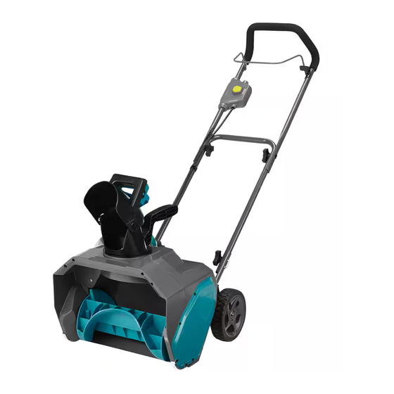
- Page 4 060-3711-6 | contact us: 1.866.523.5218 1. Handle bar 2. Bail lever 3. Safety switch button 4. Upper handle 5. Middle handle 6. Chute deflector 7. Discharge chute 8. Battery compartment 9. Carrying or lifting handle (For transport only) 10.
- Page 5 060-3711-6 | contact us: 1.866.523.5218 Some of the following symbols may be used on this product. Please study them and learn their meaning. Proper interpretation of these symbols will allow you to operate the product better and safer.
- Page 6 060-3711-6 | contact us: 1.866.523.5218 FOLLOW THESE RULES WHILE OPERATING (THE POWER TOOL) • Walk. Do not run. • Verify that the power tool is not in contact with anything before turning it on. • Stay away from impeller openings at all times. Keep face, hands, and feet away from concealed, moving, or rotating parts.
- Page 7 060-3711-6 | contact us: 1.866.523.5218 • If the power tool starts to vibrate abnormally, stop the power tool immediately and attempt to determine the cause. Vibration is generally an indication of danger. • Stop the motor and remove the battery pack whenever the operator is not in the operating position, before unclogging the impeller, and before making any repairs, adjustments, or inspections.
- Page 8 060-3711-6 | contact us: 1.866.523.5218 • Only use identical replacement parts and accessories for this power tool. The use of nonidentical parts or accessories could lead to serious injury to the user or damage the power tool, and will void the warranty.
- Page 9 Maintain the power tool with care. Follow the instructions for lubricating and changing accessories. CAUTION: Use only Yardworks approved replacement batteries, as other batteries may cause injury or damage to the snowthrower. Use with Yardworks 40 V, 4 Ah lithium-ion battery (060-7259-0).
- Page 10 060-3711-6 | contact us: 1.866.523.5218 For the proper use, maintenance and storage of this battery, it is crucially important that you read and understand the instructions given in this manual. To avoid serious injury, risk of fire, explosion and danger of electric shock or electrocution: •...
- Page 11 060-3711-6 | contact us: 1.866.523.5218 Press the battery capacity indicator (BCI) button. The lights will illuminate according to the battery’s capacity level. See chart below: BATTERY CAPACITY LIGHT METER INDICATOR (BCI) BUTTON BATTERY METER Lights Capacity 4 Green Light...
- Page 12 060-3711-6 | contact us: 1.866.523.5218 ENVIRONMENTALLY SAFE BATTERY DISPOSAL The following toxic and corrosive materials are in the batteries used in this tool battery pack: Li-ion, a toxic material. To avoid injury and risk of fire, explosion, or electric shock, and to avoid damage to the environment: •...
- Page 13 060-3711-6 | contact us: 1.866.523.5218 NOTE: The battery is not shipped fully charged. It is recommended to fully charge it before first use to ensure that maximum run time can be achieved. This lithium-ion battery will not develop a memory and may be charged at any time.
- Page 14 060-3711-6 | contact us: 1.866.523.5218 If the battery pack does not charge properly: • Check the current at the power outlet with another tool. Make sure that the outlet is not turned off. • Check that the charger contacts have not been shorted by debris or foreign material.
- Page 15 060-3711-6 | contact us: 1.866.523.5218 1. This charger can be installed hanging on a wall using two screws (not supplied). 2. Locate the placement for the charger to be wall mounted. 3. If fastening to wood studs use 2 wood screws.
- Page 16 060-3711-6 | contact us: 1.866.523.5218 12-3 12-2 12-4 12-1 23-1 23-2 23-3 23-3 23-6 23-16 23-20 23-17 23-4 23-15 23-18 23-19 23-5 23-14 23-24 23-7 23-21 23-3 23-22 23-13 23-11 23-10 23-23 23-8 23-12 23-9...
- Page 17 060-3711-6 | contact us: 1.866.523.5218 Item Description Drawing Qty. Upper handle assembly 311022604 Insulation sleeve 341062325AE Knob 3410835-19 Bolt 322011043 Middle handle 333021492AB Cord retainer 34135469A U bolt 333041205 32222301A Bolt 322011205AB Lower handle 333011492AB Screw 32201699 Rear cover assembly...
- Page 18 060-3711-6 | contact us: 1.866.523.5218 Item Description Drawing Qty. 23-1 Chute deflector 341041205AB 23-2 Discharge chute 341031492AB 23-3 Screw 32205877 23-4 Washer 34901897 23-5 Small gear 341071205 23-6 Discharge chute base 341111492AB 23-7 Scraper 341051492AB 23-8 32910131 23-9...
- Page 19 060-3711-6 | contact us: 1.866.523.5218 ASSEMBLING THE HANDLE • Align the holes on the middle handle (2) and the lower handle (3). Insert the bolts (4), and use the handle knobs (5) to tighten them. • Align the hole on the middle handle (2) and the upper handle (1). Insert the bolts (6) and...
- Page 20 060-3711-6 | contact us: 1.866.523.5218 ASSEMBLING THE DISCHARGE CHUTE • Push the chute deflector (1) until the latching tabs (2) on both sides click into the slots (3) and the posts (4) on both sides click into the keyed holes (5).
- Page 21 060-3711-6 | contact us: 1.866.523.5218 TO INSTALL BATTERY PACK • Open the battery compartment cover (1). • Slide the battery (2) down to lock it into position. The battery is fully inserted into the snowthrower when you hear an audible “click”.
- Page 22 060-3711-6 | contact us: 1.866.523.5218 TO REMOVE THE BATTERY PACK • Release the power lever to stop the engine. • Press and hold the battery latch button (3) at the top of the battery pack. • Remove the battery pack from the product.
- Page 23 060-3711-6 | contact us: 1.866.523.5218 POWERING ON AND OFF • To power on, first press the safety switch button (1). • While pressing the safety switch button with one hand, use your other hand to simultaneously pull the bail lever (2) toward you. Once the machine powers on, release the safety switch button and proceed with operation.
- Page 24 060-3711-6 | contact us: 1.866.523.5218 ADJUSTING THE CHUTE DEFLECTOR • To adjust the chute deflector (and therefore the height of the snow stream), squeeze the trigger (1) and raise or lower the chute deflector.
- Page 25 060-3711-6 | contact us: 1.866.523.5218 OPERATING TIPS • Keep the area of operation free of foreign objects that can become thrown by the impeller. Perform a thorough inspection of the area since some objects may be hidden from view by surrounding snow.
- Page 26 060-3711-6 | contact us: 1.866.523.5218 • Do not push the snowthrower with excessive force. You should push the machine gently and at a consistent speed in accordance with the unit’s throw rate. • Some parts of the snowthrower may freeze under extreme temperature conditions.
- Page 27 060-3711-6 | contact us: 1.866.523.5218 SERVICING Servicing should be performed by a qualified technician. Replacement parts for this snowthrower must be identical to the parts that they replace. If repairs are necessary, contact the toll-free helpline at 1.866.523.5218.
- Page 28 060-3711-6 | contact us: 1.866.523.5218 REPLACING THE SCRAPER The scraper is located at the bottom of the impeller housing. • Ensure that the battery is not installed in the tool. • Remove the screw (1) from each side plate that holds the scraper and the 3 screws (2) from under the machine that secure the scraper to the machine.
- Page 29 060-3711-6 | contact us: 1.866.523.5218 REPLACING THE DRIVE BELT • Ensure that the battery is not installed in the tool. • Remove the screws (1) and side wear pad (2) that secure the left side plate (3) to the frame of the snowthrower.
- Page 30 060-3711-6 | contact us: 1.866.523.5218 REPLACING THE IMPELLER 1. Remove the screws and 2. Remove the nut, plate, 3. Remove the screws and side wear pad that secure bearing and axle sleeve. side wear pad that secure the right side cover to the the left side plate to the frame of the snowthrower.
- Page 31 060-3711-6 | contact us: 1.866.523.5218 PROBLEM POSSIBLE CAUSE SOLUTION Make sure the bolts are correctly installed through the The handle is The bolts are not properly handle bars. Check to see if the not in position. seated. hand knobs are tight. Refer to Assembling the Handle section in this manual.
- Page 32 Normal deterioration of the exterior arising from the sale of its products. finish due to use or exposure. Imported by Yardworks Canada, Toronto, Canada M4S 2B8. Made in China Yardworks CANADA will not be liable for incidental or consequential loss or damage.
- Page 33 Souffleuse à neige N° de modèle : 060-3711-6 | Communiquez avec nous au 1.866.523.5218 IMPORTANT : Guide Lisez et suivez toutes les règles de sécurité et les in- d’utilisation structions de fonctionnement avant d’utiliser ce produit.
- Page 34 For problems or questions, DO NOT RETURN TO STORE. Please contact one of our Customer Service Agents who would be happy to assist you. En cas de problèmes ou si vous avez des questions, NE RETOURNEZ PAS L’ARTICLE AU MAGASIN. Contactez plutôt un de nos agents du service à...
- Page 35 N° de modèle : 060-3711-6 | Communiquez avec nous au 1.866.523.5218 FICHE TECHNIQUE FAMILIARISEZ-VOUS AVEC VOTRE SOUFFLEUSE SYMBOLES CONSIGNES DE SÉCURITÉ BATTERIE ET CHARGEUR VUE ÉCLATÉE LISTE DES PIÈCES ASSEMBLAGE FONCTIONNEMENT ENTRETIEN DÉPANNAGE GARANTIE Batterie : 40 V max., 4 Ah, lithium-ion...
-
Page 36: Table Of Contents
N° de modèle : 060-3711-6 | Communiquez avec nous au 1.866.523.5218 1. Guidon 2. Levier-barre 3. Interrupteur de sécurité 4. Guidon supérieur 5. Guidon central 6. Déflecteur de goulotte 7. Goulotte de projection 8. Compartiment de la batterie 9. Poignée de transport ou de levage (pour les déplacements seulement) - Page 37 N° de modèle : 060-3711-6 | Communiquez avec nous au 1.866.523.5218 Il se peut que certains des symboles suivants soient utilisés sur ce produit. Veuillez les étudier et en apprendre la signification. En interprétant correctement ces symboles, vous utiliserez le produit de façon plus efficace et plus sécuritaire.
-
Page 38: Guidon
N° de modèle : 060-3711-6 | Communiquez avec nous au 1.866.523.5218 RÈGLES À SUIVRE PENDANT L’UTILISATION DE (L'OUTIL ÉLECTRIQUE) • Marchez. Ne courez pas. • Vérifiez que l’outil électrique ne touche à aucun autre objet avant de le mettre en marche. - Page 39 N° de modèle : 060-3711-6 | Communiquez avec nous au 1.866.523.5218 • Veillez à ce que la turbine soit exempte de tout débris. • Ne tentez pas de nettoyer la turbine pendant que le moteur tourne. • Lorsque l’outil heurte un obstacle, éteignez l’outil électrique et retirez la batterie, puis vérifiez qu’il n’y a aucun dommage.
- Page 40 N° de modèle : 060-3711-6 | Communiquez avec nous au 1.866.523.5218 • Rangez l’outil électrique à l’intérieur. Lorsqu’il n’est pas utilisé, l’outil électrique doit être rangé à l’intérieur dans un endroit sec et fermé à clé, hors de la portée des enfants.
- Page 41 N° de modèle : 060-3711-6 | Communiquez avec nous au 1.866.523.5218 RÈGLES DE SÉCURITÉ GÉNÉRALES • Vérifiez que l’outil électrique est sécuritaire lorsque vous le transportez. • Rangez l’outil électrique dans un endroit sec afin d’éviter qu’il ne soit utilisé sans votre autorisation ou qu’il soit endommagé.
- Page 42 N° de modèle : 060-3711-6 | Communiquez avec nous au 1.866.523.5218 Pour une bonne utilisation, un bon entretien et un bon rangement de cette batterie, il est essen- tiel que vous lisiez et compreniez les instructions présentes dans ce guide.
- Page 43 N° de modèle : 060-3711-6 | Communiquez avec nous au 1.866.523.5218 Appuyez sur le bouton de vérification de charge (BCI) de la batterie. Les voyants s’illumineront en fonction de du niveau de charge de la batterie. Reportez-vous au tableau ci-dessous :...
- Page 44 N° de modèle : 060-3711-6 | Communiquez avec nous au 1.866.523.5218 MISE AU REBUT DE LA BATTERIE DE FAÇON ÉCOLOGIQUE Les matériaux toxiques et corrosifs suivants se trouvent dans les éléments composant la batterie de cet outil : lithium-ion, un matériau toxique.
- Page 45 N° de modèle : 060-3711-6 | Communiquez avec nous au 1.866.523.5218 REMARQUE : La batterie n’est pas livrée totalement chargée. Il est recommandé de la re- charger totalement avant de l’utiliser pour assurer une autonomie maximale. Cette batterie au lithium-ion est exempte d’effet mémoire et peut être rechargée à tout moment.
- Page 46 N° de modèle : 060-3711-6 | Communiquez avec nous au 1.866.523.5218 Si la batterie ne se recharge pas correctement : • Vérifiez la prise secteur à l’aide d’un autre appareil. Assurez-vous que le courant n’est pas coupé dans cette prise.
- Page 47 N° de modèle : 060-3711-6 | Communiquez avec nous au 1.866.523.5218 Ce chargeur peut être accroché au mur à l’aide de deux vis (non fournies). Repérez l’emplacement où vous allez accrocher le chargeur. Si l’emplacement est en bois, utilisez 2 vis à bois.
- Page 48 N° de modèle : 060-3711-6 | Communiquez avec nous au 1.866.523.5218 12-3 12-2 12-4 12-1 23-1 23-2 23-3 23-3 23-6 23-16 23-20 23-17 23-4 23-15 23-18 23-19 23-5 23-14 23-24 23-7 23-21 23-3 23-22 23-13 23-11 23-10 23-23 23-8 23-12...
-
Page 49: Guidon Supérieur
N° de modèle : 060-3711-6 | Communiquez avec nous au 1.866.523.5218 Nº de réf. Description Code Qté Guidon supérieur 311022604 Manchon d'isolation 341062325AE Bouton 3410835-19 Boulon 322011043 Guidon central 333021492AB Crochet de rétention du cordon 34135469A Boulon en U 333041205 Écrou... -
Page 50: Déflecteur De Goulotte
N° de modèle : 060-3711-6 | Communiquez avec nous au 1.866.523.5218 Nº de réf. Description Code Qté 23-1 Déflecteur de goulotte 341041205AB 23-2 Goulotte de projection 341031492AB 23-3 32205877 23-4 Rondelle 34901897 23-5 Petit engrenage 341071205 23-6 Suppose de la goulotte d'éjection... - Page 51 N° de modèle : 060-3711-6 | Communiquez avec nous au 1.866.523.5218 DÉPLIER ET RÉGLER LE GUIDON • Alignez les trous du guidon central (2) avec les trous du guidon inférieur (3). Insérez les boulons (4) et serrez l’ensemble à l’aide des boutons du guidon (5).
- Page 52 N° de modèle : 060-3711-6 | Communiquez avec nous au 1.866.523.5218 ASSEMBLAGE DE LA GOULOTTE DE PROJECTION • Poussez sur le déflecteur de la goulotte (1) jusqu’à ce que, de chaque côté, les pattes de verrouillage (2) s’enclenchent dans les fentes de retenue (3) et les tenons (4)
- Page 53 N° de modèle : 060-3711-6 | Communiquez avec nous au 1.866.523.5218 INSTALLATION DE LA BATTERIE • Ouvrez le couvercle (1) du compartiment de la batterie. • Faites glisser la batterie (2) vers le bas pour la verrouiller en position. La batterie est insérée complètement dans la souffleuse quand vous entendez un «...
- Page 54 N° de modèle : 060-3711-6 | Communiquez avec nous au 1.866.523.5218 POUR ENLEVER LA BATTERIE • Lâchez le levier d’alimentation pour arrêter le moteur. • Maintenez enfoncé le loquet (3) sur le dessus de la batterie. • Retirez la batterie de la souffleuse.
- Page 55 N° de modèle : 060-3711-6 | Communiquez avec nous au 1.866.523.5218 MISE EN MARCHE ET ARRÊT • Pour la mise en marche, pressez d’abord l’interrupteur de sécurité (1). • Tout en appuyant sur l’interrupteur de sécurité d’une main, utilisez l’autre main pour tirer le levier-barre (2) vers vous en même temps.
- Page 56 N° de modèle : 060-3711-6 | Communiquez avec nous au 1.866.523.5218 RÉGLAGE DU DÉFLECTEUR • Pour régler le déflecteur de la goulotte (et, ainsi, la hauteur de projection), pressez la détente (1) et montez ou descendez le déflecteur.
- Page 57 N° de modèle : 060-3711-6 | Communiquez avec nous au 1.866.523.5218 CONSEILS D’UTILISATION • Maintenez la zone de travail exempte d’objets étrangers pouvant être projetés par les pales de la turbine. Effectuez une inspection approfondie de la zone car certains objets peuvent être dissimulés sous la neige.
- Page 58 N° de modèle : 060-3711-6 | Communiquez avec nous au 1.866.523.5218 • Ne poussez pas la souffleuse à neige avec une force excessive. Poussez la machine doucement et uniformément, suivant la vitesse de projection de la machine. • Certaines pièces de la souffleuse à neige peuvent geler sous des conditions de températures extrêmes.
- Page 59 N° de modèle : 060-3711-6 | Communiquez avec nous au 1.866.523.5218 RÉPARATION La réparation doit être effectuée par un technicien qualifié. Les pièces de rechange de la souffleuse doivent être identiques à celles qu’elles remplacent. Pour le remplacement de toute pièce, communiquez avec le service d’assistance téléphonique sans frais au 1.866.523.5218.
- Page 60 N° de modèle : 060-3711-6 | Communiquez avec nous au 1.866.523.5218 REMPLACEMENT DU RACLOIR Le racloir est situé en bas du caisson de la turbine. • Assurez-vous que la batterie n’est pas installée dans l’outil. • Retirez la vis (1) des carters de chaque côté du racloir et les trois vis (2) en dessous du racloir qui fixent ce dernier à...
- Page 61 N° de modèle : 060-3711-6 | Communiquez avec nous au 1.866.523.5218 REMPLACEMENT DE LA COURROIE • Assurez-vous que la batterie n’est pas installée dans l’outil. • Retirez les vis (1) et la plaque d’usure latérale (2) qui fixent la plaque gauche (3) au châssis de la souffleuse.
- Page 62 N° de modèle : 060-3711-6 | Communiquez avec nous au 1.866.523.5218 REMPLACEMENT DE LA TURBINE 1. Retirez les vis et la plaque 2. Retirez l’écrou, la plaque, 3. Retirez les vis et la plaque d’usure latérale qui fixent le le roulement et le manchon d’usure latérale qui fixent le...
-
Page 63: Racloir
N° de modèle : 060-3711-6 | Communiquez avec nous au 1.866.523.5218 PROBLÈME POSSIBLE CAUSE SOLUTION Assurez-vous que les boulons soient bien serrés dans le Le guidon est guidon. Vérifiez si les boutons Les boulons sont desserrés. mal positionné. du guidon sont serrés. Reportez- vous à... - Page 64 N° de modèle : 060-3711-6 | Communiquez avec nous au 1.866.523.5218 GARANTIE LIMITÉE DE 2 ANS COMMENT OBTENIR UN SERVICE Pour tout service relatif à la garantie, Pour une période de deux ans à compter communiquez avec le service d’assistance de la date d’achat au Canada, Yardworks...
Need help?
Do you have a question about the 060-3711-6 and is the answer not in the manual?
Questions and answers