
Related Manuals for Yardworks 60-3982-0


Summary of Contents for Yardworks 60-3982-0
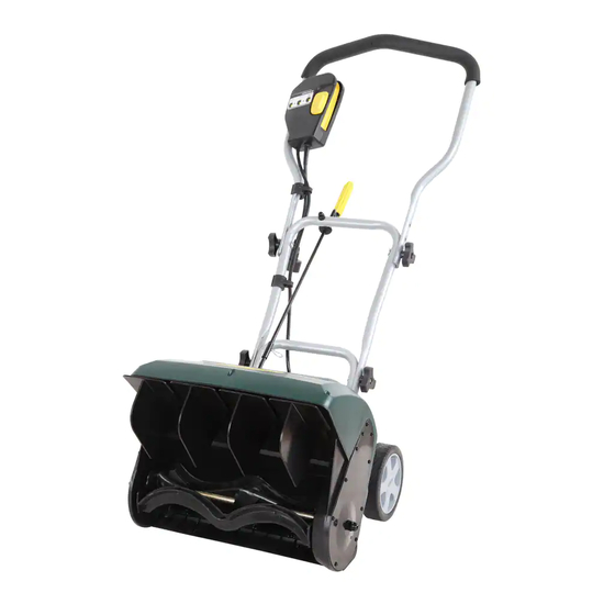
- Page 1 Electric Snow Thrower 60-3982-0 Owner's Manual TOLL-FREE HELPLINE: 1 866 523-5218 IMPORTANT: Read all safety rules and instructions carefully before using this product.
-
Page 2: Table Of Contents
TABLE OF CONTENTS Specifications ................2 General Safety Rules. -
Page 3: General Safety Rules
16" (40.6 cm) Electric Snow Thrower 120 V, 60 Hz, 10 A 60-3982-0 Made in China/Fabrique en Chine Serial #/N* de serie: CTxx xxxxxx In order to avoid injury, keep hands, feet, and clothing away from the rotating auger. - Page 4 GENERAL SAFETY RULES Electrical Information WARNING: To avoid electrical hazards, fire hazards, or damage to the tool, use proper circuit protection. The Snow Thrower is wired at the factory for 120 V operation. Connect to a 120 V, 15 A circuit and use a 15 A time delayed fuse or circuit breaker.
- Page 5 GENERAL SAFETY RULES FOLLOW THESE RULES WHILE OPERATING THE SNOW THROWER • Walk. Do not run. • Verify that the Snow Thrower is not in contact with anything before turning it on. • Stay away from the discharge opening at all times. Keep face, hands, and feet away from concealed, moving, or rotating parts.
- Page 6 GENERAL SAFETY RULES • Use only the manufacturer's original replacement parts and accessories for this Snow Thrower. The use of unauthorized parts or accessories could lead to serious injury to the user or damage the Snow Thrower, and will void the warranty. •...
-
Page 7: Assembly Instructions
ASSEMBLY Assembling the Handle (Fig. 1) 1. Remove any packing material that may have been inserted between the upper and lower handles for shipping purposes. 2. Align the holes (4) on the upper handle (1) with the holes on the middle handle (2). Insert the bolts (5), and use the wing nuts (6) to tighten them. -
Page 8: Diagram And Location Of Parts
Diagram and Location of Parts Diagram and Location of Parts (Fig. 2) Fig. 2 Switch Discharge Directional Control Upper Handle Lower Handle Middle Handle Wheels Vanes Cover Screws Impeller Belt Cover Scraper... -
Page 9: Operating Instructions
OPERATING INSTRUCTIONS Starting the Snow Thrower WARNING: Avoid accidental start-ups. Verify that the operator is in the starting position when using the snow thrower. In order to avoid serious injury, the operator and unit must be in a stable position when starting the Snow Thrower. - Page 10 OPERATING INSTRUCTIONS Adjusting the Direction of Discharge (Fig. 3-4) Snow can be discharged to the left, straight ahead, or to the right of the operator. Follow these instructions in order to change the direction of the discharge: 1. Release the switch bar in order to stop the rotor. NOTE: The control stick can revolve 720°.
-
Page 11: Maintenance
MAINTENANCE Servicing Servicing should be performed by a qualified technician. Replacement parts for this Snow Thrower must be identical to the parts that they replace. If repairs are necessary, contact the Toll-Free Helpline, at 1-866-523-5218. Inspecting/Replacing the Drive Belt (Fig. 5-7) When servicing the Snow Thrower, use only the manufacturer's original replacement parts. - Page 12 MAINTENANCE Impellor replacement spring 1. Remove the nut from the left hand side of 2. Remove the 10 screws from the side cover. 3. Be sure not to lose the 2 springs. the impellor shaft. spacer washer washer and screw 4.
- Page 13 MAINTENANCE Impellor replacement 13. Place the pulley back onto the impellor 14. Be sure to route the belt correctly, as 15. Replace the 2 spacer washers on the shaft. shown. impellor shaft. washer and screw impellor shaft washer and nut 18.
- Page 14 (Fig. 8) (Fig. 8) Fig. 8...
-
Page 15: Troubleshooting
TROUBLESHOOTING Problem Possible Causes Solutions Then handle is not in The carriage bolts are not properly Adjust the height of the handle, and verify position. seated that the carriage bolts are properly seated. Tighten the knobs. The Snow Thrower The Snow Thrower is unplugged. Verify that the Snow Thrower is plugged into does not start. -
Page 16: Warranty
WARRANTY For TWO YEARS from the date of purchase within Canada, YARDWORKS CANADA will, at its option, repair or replace for the original purchaser, free or charge, any part or parts found to be defective in material or workmanship. This warranty does not cover: 1. -
Page 17: Exploded View
PARTS LIST... -
Page 18: Parts List
PARTS LIST Model num. Description Model num. Description 3118099 Upper handle assembly 3225599 Screw Screw 3220436 3320299-A Impeller shaft 3410835-4 Knob 3331399 Auxiliary board 3221099 Screw 3330299-3 Middle handle 3330399-3 Down handle 3410999A Vanes 3290135 Clip pin 3331199 Right inside steel support 3220199 Screw 3411099...
Need help?
Do you have a question about the 60-3982-0 and is the answer not in the manual?
Questions and answers
Can I buy a impeller