Advertisement
Advertisement
Table of Contents

Related Manuals for Yardworks 31AM63KE515


Summary of Contents for Yardworks 31AM63KE515
- Page 1 Safety • Assembly • Operation • Adjustments • Maintenance • Troubleshooting • Parts Lists • Warranty OPERATOR’S MANUAL IMPORTANT: READ SAFETY RULES AND INSTRUCTIONS CAREFULLY BEFORE OPERATION. FOR CUSTOMER ASSISTANCE CALL 1-866-523-5218 769-06142A PRINTED IN U.S.A. 07/14/11...
-
Page 2: Table Of Contents
To The Owner Thank You Thank you for purchasing your new equipment. It was carefully The manufacturer reserves the right to change product engineered to provide excellent performance when properly specifications, designs and equipment without notice and operated and maintained. without incurring obligation. -
Page 3: Safe Operation Practices
Important Safe Operation Practices WARNING! This symbol points out important safety instructions which, if not followed, could endanger the personal safety and/or property of yourself and others. Read and follow all instructions in this manual before attempting to operate this machine. Failure to comply with these instructions may result in personal injury. - Page 4 Safe Handling of Gasoline Never run an engine indoors or in a poorly ventilated area. Engine exhaust contains carbon monoxide, an odorless To avoid personal injury or property damage use extreme care and deadly gas. in handling gasoline. Gasoline is extremely flammable and the Do not operate machine while under the influence of vapors are explosive.
- Page 5 Clearing a Clogged Discharge Chute According to the Consumer Products Safety Commission (CPSC) and the U.S. Environmental Protection Agency (EPA), Hand contact with the rotating impeller inside the discharge this product has an Average Useful Life of seven (7) years, chute is the most common cause of injury associated with snow or 60 hours of operation.
- Page 6 Safety Symbols This page depicts and describes safety symbols that may appear on this product. Read, understand, and follow all instructions on the machine before attempting to assemble and operate. Symbol Description READ THE OPERATOR’S MANUAL(S) Read, understand, and follow all instructions in the manual(s) before attempting to assemble and operate.
-
Page 7: Assembly & Set-Up
Assembly & Set-Up IMPORTANT: The snow thrower is shipped with oil and WITHOUT GASOLINE. After assembly, refer to separate engine manual for proper fuel and engine oil recommendations. NOTE: Remove all loose parts and any packing material before assembling. NOTE: References to right or left side of the snow thrower are determined from behind the unit in the operating position. NOTE: This Operator’s Manual covers several models, handle panels, lights and chute cranks are some features that may vary by model. - Page 8 IMPORTANT: Prior to operating your snow thrower, refer to Close the flange keepers to secure the chute assembly to the chute base. The flange keepers will click into place Auger Control Test on page 11. Read and follow all instructions when properly secure.
- Page 9 Clean-Out Tool Lamp Wiring Harness (If equipped) The clean-out tool is mounted to the rear of the auger housing The post on the cable tie attaching the lamp wiring harness to and is designed to clear a clogged chute. Refer to page 13 for the lower handle should be plugged into the hole in the lower instructions on how to properly use it.
- Page 10 Adjustment Skid Shoes The snow thrower skid shoes are adjusted upward at the factory Chute Assembly for shipping purposes. Adjust them downward, if desired, prior The distance snow is thrown can be adjusted by changing the to operating the snow thrower. angle of the chute assembly.
- Page 11 Fig. 3-13 Fig. 3-12 NOTE: Some models are equipped with reversible skid shoes Allow the auger to remain engaged for approximately ten and may be turned over to increase their lifespan. (10) seconds before releasing the auger control. Repeat this several times.
-
Page 12: Controls
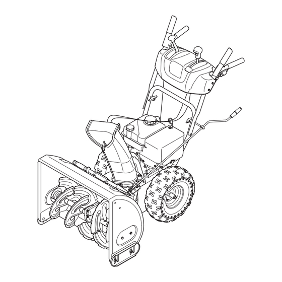
Controls and Features Drive Control Shift Lever Two-Way Chute Control™ (optional) Auger Control Headlight (optional) Chute Directional Control Drift Cutters Chute (optional) Assembly Clean-Out Tool Augers Skid Shoe Fig. 4-1 Skid Shoes Snow thrower controls and features are described below and illustrated in Fig. - Page 13 Drift Cutters (if so equipped) Chute Clean-Out Tool The drift cutters are designed for use in deep snow. Their use WARNING! Never use your hands to clear a is optional for normal snow conditions. Maneuver the snow clogged chute assembly. Shut off engine and remain thrower so that the cutters penetrate a high standing snow drift behind handles until all moving parts have stopped to assist snow falling into the augers for throwing.
- Page 14 Two-Way Chute Control™ (optional) CHUTE DIRECTIONAL CONTROL This two-way control lever is meant to control the distance of snow discharge from the chute. Tilt the lever forward or rearward to adjust the distance snow will be thrown. Chute Directional Control (optional) DISCHARGE DISCHARGE RIGHT...
-
Page 15: Operation
Operation Starting and Stopping the Engine Replacing Shear Pins Refer to the Engine Operator’s Manual packed with your snow The augers are secured to the spiral shaft with two shear thrower for instructions on starting and stopping the engine. pins and cotter pins. If the auger should strike a foreign object or ice jam, the snow thrower is designed so that the To Engage Drive pins may shear. -
Page 16: Maintenance & Adjustment
Maintenance & Adjustments Maintenance Lubrication Engine Gear Shaft Refer to the Engine Operator’s Manual packed with your snow The gear (hex) shaft should be lubricated at least once a season thrower. or after every twenty-five (25) hours of operation. Allow the engine to run until it is out of fuel. Tire Pressure Carefully pivot the snow thrower up and forward so that it Refer to “Assembly &... - Page 17 Chute Assembly Refer to the Assembly & Set-up section for instructions on adjusting the chute assembly. Skid Shoes Refer to the Assembly & Set-up section for instructions on adjusting the skid shoes. Drive Control When the drive control is released and in the disengaged “up” position, the cable should have very little slack.
- Page 18 Off-Season Storage If the snow thrower will not be used for 30 days or longer, follow the storage instructions below. Lubricate the machine as instructed earlier in this section. Store in a clean, dry area. If storing the snow thrower in an unventilated area, rustproof the machine using a light oil or silicone to coat the snow thrower.
-
Page 19: Service
Service Belt Replacement Carefully pivot the snow thrower up and forward so that it rests on the auger housing. Auger Belt Remove the frame cover from the underside of the snow thrower by removing the self-tapping screws which secure To remove and replace your snow thrower’s auger belt, proceed it. - Page 20 Remove the belt from around the auger pulley, and slip the Drive Belt belt between the support bracket and the auger pulley. To remove and replace your snow thrower’s drive belt, proceed See Fig. 7-5. as follows: To prevent spillage, remove all fuel from tank by running engine until it stops.
- Page 21 Friction Wheel Removal (600 Series) Back out the stop bolt to increase the clearance between the friction wheel disc and friction wheel. See Fig. 7-7. If the snow thrower fails to drive with the drive control engaged, and performing the drive control cable adjustment fails to correct the problem, the friction wheel may need to be replaced.
- Page 22 Carefully remove the hex nut which secures the hex shaft Follow the previous steps in reverse order to reassemble to the snow thrower frame and lightly tap the shaft’s end to components. dislodge the ball bearing from the right side of the frame. After replacing the friction wheel, perform the Drive See Fig.
-
Page 23: Troubleshooting
Troubleshooting Problem Cause Remedy Engine fails to start 1. Choke not in CHOKE position. 1. Move choke to CHOKE position. 2. Spark plug wire disconnected. 2. Connect wire to spark plug. 3. Fuel tank empty or stale fuel. 3. Fill tank with clean, fresh gasoline. 4. -
Page 24: Replacement Parts
Replacement Parts Component Part Number and Description 929-0071A Extension Cord, 110V 954-04050 Auger Drive Belt (24”) 954-04260 Wheel Drive Belt (24”) 954-04195 Auger Drive Belt (26”, 28” & 30”) 954-04201A Wheel Drive Belt (26”, 28” & 30”) 684-04159 Friction Wheel Assembly (500 Series) 684-04153 Friction Wheel Assembly 600 Series) 935-04054... -
Page 25: Warranty
4 YEAR LIMITED WARRANTY For FOUR YEARS from the date of retail purchase within Canada, YARDWORKS CANADA will, at its option, repair or replace, for the original purchaser, free of charge, any part or parts found to be defective in material or workmanship. -
Page 26: Emission Control Warranty Statement
FEDERAL and/or CALIFORNIA EMISSION CONTROL WARRANTY STATEMENT YOUR WARRANTY RIGHTS AND OBLIGATIONS MTD Consumer Group Inc, the United States Environmental Protection Agency (EPA), and, for those products certified for sale in the state of California, the California Air Resources Board (CARB) are pleased to explain the emission (evaporative and/or exhaust) control system (ECS) warranty on your outdoor 2006 and later small off-road spark-ignited engine and equipment (outdoor equipment engine) In California, new outdoor equipment engines must be designed, built and equipped to meet the State’s stringent anti-smog standards (in other states, 1997 and later model year equipment must be designed, built, and equipped to meet the U.S. - Page 27 6. The outdoor equipment engine owner will not be charged for diagnostic labor that is directly associated with diagnosis of a defec- tive, emission-related warranted part, provided that such diagnostic work is performed at a warranty station. 7. MTD Consumer Group Inc is liable for damages to other engine or equipment components proximately caused by a failure under warranty of any warranted part.
- Page 28 Notes...
- Page 29 Notes...
Need help?
Do you have a question about the 31AM63KE515 and is the answer not in the manual?
Questions and answers
How to remove wheel
To remove the wheel on a Yardworks 31AM63KE515:
1. Remove the rubber ring from between the plates.
2. Reassemble the side plates with a new rubber ring if needed.
3. Ensure the rubber ring is centered and seated properly between the side plates.
4. Tighten each screw one rotation at a time while turning the wheel clockwise, repeating this process to secure the plates evenly (between 6 ft-lbs and 9 ft-lbs).
5. Ensure the shift lever pin is in place in the bearing housing.
6. Slide the friction wheel assembly back onto the hex shaft and reassemble components in reverse order.
7. After replacing the friction wheel, perform the Drive Control test as specified in the Maintenance and Adjustments section.
This answer is automatically generated