
Related Manuals for Yardworks 60-3983-8


Summary of Contents for Yardworks 60-3983-8
- Page 1 Electric Snow Thrower 60-3983-8 Owner's Manual TOLL-FREE HELPLINE: 1 866 523-5218 IMPORTANT: Read all safety rules and instructions carefully before using this product.
-
Page 2: Table Of Contents
TABLE OF CONTENTS Specifications................................2 General Safety Rules..............................3-7 Assembly Instructions..............................8-9 Diagram and Location of Parts............................10 Operating Instructions............................11-13 Maintenance................................14-15 Troubleshooting................................16 Warranty..................................17 Exploded view/Parts List............................18-20 SPECIFICATIONS Motor 120 V, 60 Hz, 12 A Blade Speed 2,400 RPM Clearing width 20”... -
Page 3: General Safety Rules
DANGER: Failure to obey safety warnings will result in serious injury to the operator or to others. Follow the safety precautions in order to reduce the risk of fire, electric shock, and personal injury. 120 V, 60 Hz, 12 A 60-3983-8 Made in China/Fabrique en Chine Serial #/N* de serie: CTxxxxxxxx In order to avoid injury, keep hands, feet, and clothing away from the rotating auger. - Page 4 GENERAL SAFETY RULES Electrical Information WARNING: To avoid electrical hazards, fire hazards, or damage to the tool, use proper circuit protection. The Snow Thrower is wired at the factory for 120 V operation. Connect to a 120 V, 15 A circuit and use a 15 A time delayed fuse or circuit breaker.
- Page 5 GENERAL SAFETY RULES FOLLOW THESE RULES WHILE OPERATING THE SNOW THROWER • Walk. Do not run. • Verify that the Snow Thrower is not in contact with anything before turning it on. • Stay away from the discharge opening at all times. Keep face, hands, and feet away from concealed, moving, or rotating parts.
- Page 6 GENERAL SAFETY RULES FOLLOW THESE RULES WHILE OPERATING THE SNOW THROWER • Use the proper tool. Only use this Snow Thrower for the purpose that it was designed for. • Do not overreach. Always keep proper footing and balance. • Hold the Snow Thrower with both hands while it is in use. Keep a firm grip on the handles or the grips. •...
- Page 7 GENERAL SAFETY RULES OTHER SAFETY WARNINGS • Verify that the Snow Thrower is secure while transporting. • Store the Snow Thrower in a dry area, locked up or high enough to prevent unauthorized use or damage, and out of the reach of children. •...
-
Page 8: Assembly Instructions
ASSEMBLY INSTRUCTIONS Assembling the Handle (Fig. 1) 1. Remove any packing material that may have been inserted between the upper and lower handles for shipping purposes. 2. Align the holes (4) on the upper handle (1) with the holes on the middle handle (2). Insert the bolts (5), and use the wing nuts (6) to tighten them. - Page 9 ASSEMBLY INSTRUCTIONS Assembling the Directional Chute Arm to directional chute pinion (Fig. 2) Align the holes (1) on the directional chute arm (2) with the holes on the lower directional chute arm (3). Insert the hitch pin (4). (Fig. 2.1) Assembling the Discharge Directional Arm Control to the center handle (Fig.
-
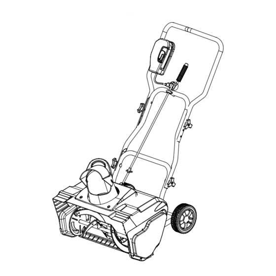
Page 10: Diagram And Location Of Parts
DIAGRAM AND LOCATION OF PARTS Fig. 3 Discharge Directional Upper Control Handle Middle Handle Chute Discharge deflector chute Lower Handle Wheels Cover Rotor Scraper Cover Screws... -
Page 11: Operating Instructions
OPERATING INSTRUCTIONS Starting the Snow Thrower WARNING: Avoid accidental start-ups. Verify that the operator is in the starting position when using the snow thrower. In order to avoid serious injury, the operator and unit must be in a stable position when start- ing the Snow Thrower. - Page 12 OPERATING INSTRUCTIONS Adjusting the Direction of Discharge Snow can be discharged to the left, straight ahead, or to the right of the operator. Follow these instructions in order to change the direction: 1. Release the safety switch in order to stop the rotor. NOTE: The control crank can revolve 810°.
- Page 13 OPERATING INSTRUCTIONS • Keep the extension cord clear of obstructions, sharp objects, and all moving parts. Do not pull sharply on the cord or abuse it in any manner. Inspect the extension cord for damage that may result in an electric shock on a regular basis.
-
Page 14: Maintenance
MAINTENANCE Servicing Servicing should be performed by a qualified technician. Replacement parts for this Snow Thrower must be identical to the parts that they replace. If repairs are necessary, contact the Toll-Free Helpline, at 1-866-523-5218. Note: Identify the left and right sides of the Snow Thrower when standing in the normal operating position. WARNING: If the extension cord is plugged into the Snow Thrower, the Snow Thrower could start accidentally while the operator is performing maintenance on it, which could cause serious personal injury. - Page 15 MAINTENANCE Replacing the Large Belt 1. Remove the 4 screws that secure the left side plate to the frame of the Snow Thrower (Fig. 10). Remove the side plate. 2. Pull the bearing away from the small pulley. Remove the belt from the large pulley and the small pulley that is located inside the housing (Fig.11).
-
Page 16: Troubleshooting
TROUBLESHOOTING Problem Possible Causes Solutions The handle is The carriage bolts are not properly seated Adjust the height of the handle, and verify not in position. that the carriage bolts are properly seated. Tighten the knobs. Snow The power cord is disconnected from the Reconnect the cord, and use the cord Thrower does not switch. -
Page 17: Warranty
WARRANTY For TWO YEARS from the date of purchase within Canada, YARDWORKS CANADA will, at its option, repair or replace for the original purchaser, free or charge, any part or parts found to be defective in material or workmanship. This warranty does not cover: 1. -
Page 18: Exploded View/Parts List
EXPLODED VIEW/PARTS LIST... - Page 19 EXPLODED VIEW/PARTS LIST ITEM NO. PART NO. DESCRIPTION 33306100 Left side board 3290198 Belt 34901100 Strap 33212100 32104100 Tensioner bearing 33211100 Tensioner shaft 33903100 Tensioner spring 34165100 Motor vent cover 32201100 Locknut 33305100 Tensioner bracket 3290699 Washer 32203100 Cross screw 33301100-2 Motor support 31120100-1...
-
Page 20: Exploded View/Parts List
EXPLODED VIEW/PARTS LIST ITEM NO. PART NO. DESCRIPTION 3420199 Rubber 3410499-1 Handle 33306699 Washer 32901251 Retaining ring 3330199-3 Upper handle 3490137-1 Soft grip sponge 3290599 33214100-3 Rear rocker 3320643 Hitch pin 33214100-2 Upper rocker 3220436 Bolt 3410835-8 Knob 3290135 Split pin 3411799C Wheel cover 3220898...
Need help?
Do you have a question about the 60-3983-8 and is the answer not in the manual?
Questions and answers
can you adjust the belt for more tension on the thrower