Samson 3730 Series Mounting And Operating Instructions
Electropneumatic positioner
Hide thumbs
Also See for 3730 Series:
- Mounting and operating instructions (220 pages) ,
- Operating instructions manual (120 pages) ,
- Mounting and operating instructions (104 pages)

Related Manuals for Samson 3730 Series


Summary of Contents for Samson 3730 Series
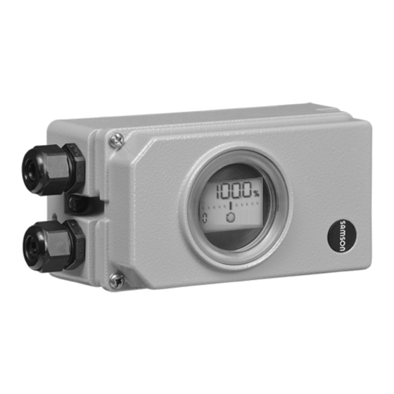
- Page 1 EB 8384-4 EN Translation of original instructions Old design New design Series 3730 Type 3730-4 Electropneumatic Positioner Communication: PROFIBUS-PA Firmware version K 2.02/R 1.53 Edition April 2022...
- Page 2 Note on these mounting and operating instructions These mounting and operating instructions assist you in mounting and operating the device safely. The instructions are binding for handling SAMSON devices. The images shown in these instructions are for illustration purposes only. The actual product may vary.
-
Page 3: Table Of Contents
Contents Safety instructions and measures ..............1-1 Notes on possible severe personal injury ............1-4 Notes on possible personal injury ..............1-4 Notes on possible property damage .............1-5 Special instructions concerning explosion protection ........1-7 Markings on the device ................2-1 Nameplate ....................2-1 Article code ....................2-2 Firmware versions ..................2-3 Design and principle of operation ...............3-1 Mounting versions ..................3-2... - Page 4 Contents 5.6.1 Mounting the position sensor with direct attachment ........5-31 5.6.2 Mounting the position sensor with attachment according to IEC 60534-6 ..5-32 5.6.3 Mounting the position sensor to Type 3510 Micro-flow Valve ......5-34 5.6.4 Mounting on rotary actuators ..............5-35 Mounting the leakage sensor ..............5-36 5.8 Retrofitting inductive limit switch ..............5-37 Mounting positioners with stainless steel housings ........5-38 5.10 Air purging function for single-acting actuators ...........5-38 5.11 Pneumatic connection ................5-40 5.11.1...
- Page 5 Periodic inspection and testing of the positioner ...........10-2 Decommissioning ..................11-1 Removal ....................12-1 Repairs ....................13-1 13.1 Servicing explosion-protected devices ............13-1 13.2 Returning devices to SAMSON ..............13-1 Disposal ....................14-1 Certificates ....................15-1 Annex A (configuration instructions) ............16-1 16.1 Parameters and functions ................16-1 16.1.1 Error codes ....................16-8...
- Page 6 EB 8384-4 EN...
-
Page 7: Safety Instructions And Measures
In case operators intend to use the positioner in applications or conditions other than those specified, contact SAMSON. SAMSON does not assume any liability for damage resulting from the failure to use the de- vice for its intended purpose or for damage caused by external forces or any other external factors. - Page 8 Î Check with the plant operator for details on further protective equipment. Revisions and other modifications Revisions, conversions or other modifications of the product are not authorized by SAMSON. They are performed at the user's own risk and may lead to safety hazards, for example. Fur- thermore, the product may no longer meet the requirements for its intended use.
- Page 9 Safety instructions and measures Responsibilities of operating personnel Operating personnel must read and understand these mounting and operating instructions as well as the specified hazard statements, warning and caution notes. Furthermore, the operat- ing personnel must be familiar with the applicable health, safety and accident prevention regulations and comply with them. Referenced standards, directives and regulations Devices with a CE marking fulfill the following requirements of the Directives: −...
-
Page 10: Notes On Possible Severe Personal Injury
Safety instructions and measures 1.1 Notes on possible severe personal injury DANGER Risk of fatal injury due to the ignition of an explosive atmosphere. Incorrect installation, operation or maintenance of the positioner in potentially explosive atmospheres may lead to ignition of the atmosphere and ultimately to death. Î... -
Page 11: Notes On Possible Property Damage
Safety instructions and measures Intrinsic safety rendered ineffective in intrinsically safe devices. Every time the positioner is operated, even not within the plant (e.g. during maintenance, calibration and work on equipment), it must be ensured that the conditions for intrinsical- ly safe circuits are observed. - Page 12 Safety instructions and measures Malfunction due to initialization not yet completed. The initialization causes the positioner to be calibrated to adapt it to the mounting situa- tion. After initialization is completed, the positioner is ready for use. Î Initialize the positioner on first start-up. Î Re-initialize positioner after changing the mounting position. Risk of positioner damage due to incorrect grounding of the electric welding equip- ment.
-
Page 13: Special Instructions Concerning Explosion Protection
Safety instructions and measures 1.4 Special instructions concerning explosion protection Explosive dust atmospheres of zone 21 or zone 22 Î The following applies to type of protection Ex i in combustible dust atmospheres: – If intrinsic safety is impaired by the influence of dust, an enclosure complying with Clause 6.1.3 of EN 60079-11 with at least degree of protection IP 5X must be used. The requirements according to Clause 6.1.3 apply to the cable entries and conduit systems accordingly. – The degree of ingress protection is verified by a test according to IEC 60529 and EN 60079-0 (e.g. performed by VDE). Î For use in the presence of combustible dust in compliance with type of protection Ex tb IIIC (protection by enclosure), observe clause 5.6.3 of EN 60079-14. - Page 14 – EN 60079-19 applies to servicing explosion-protected devices. – Use the protective cable designed by SAMSON when interconnecting non-intrin- sically safe set point calibrators with intrinsically safe equipment for repair, cali- bration etc. to ensure that components relevant to explosion protection are not damaged. EB 8384-4 EN...
-
Page 15: Markings On The Device
10 Data Matrix code Var.-ID Serial no. certificate for permissible (electronic nameplate) Model ambient temperature 11 Explosion protection marking and maximum values for SAMSON AG D-60314 Frankfurt Made in Germany connection to certified intrinsically safe circuits. Diagnostics Firmware Date Var.-ID Serial no. -
Page 16: Article Code
Markings on the device 2.2 Article code Positioner Type 3730-4 x x x 0 x 0 x x 1 x 0 0 x 0 x x With LCD and autotune, PROFIBUS-PA Explosion protection Without ATEX II 2G Ex ia IIC T6 Gb; II 2D Ex ia III T80°C Db Ex ia IIC T6, Class I, II, Div. 1, Groups A–G; Ex nA II T6, Ex nL IIC T6;... -
Page 17: Firmware Versions
Markings on the device Positioner Type 3730-4 x x x 0 x 0 x x 1 x 0 0 x 0 x x With additional vent hole Special version Without 0 0 0 CCC Ex Ex ia IIC T4 ~ T6 Gb 0 0 9 CCC Ex Ex ic IIC T4 ~ T6 Gc;... - Page 18 Markings on the device Firmware revisions (Communication K) K 1.01 Internal revisions K 1.10 The FEATURE_SELECT parameter allows you to set whether an active diagnostic function is to be re- ported by a GOOD_FUNCTION_CHECK or a BAD_FUNCTION_CHECK (u KH 8384-4). K 1.11 • More trigger conditions in the data logger (u KH 8384-4). •...
-
Page 19: Design And Principle Of Operation
Design and principle of operation 3 Design and principle of oper- er with a downstream air booster and the electronics with the microcontroller. ation When a system deviation occurs, the actua- Î See Fig. 3-1 tor is either vented or filled with air. If neces- The positioner is mounted on pneumatic con- sary, the signal pressure change can be trol valves and used to assign the valve posi- slowed down by a volume restriction. -
Page 20: Mounting Versions
In this version, only the sensor is mounted to accessories: the control valve. The positioner is located separately from the valve. The connection of − Direct attachment to SAMSON x and y signals to the valve is established by Type 3277 Actuator cable and piping for air (only without induc- −... -
Page 21: Communication
TROVIS-VIEW provides a uniform user inter- digital signal transmission according to face that allows users to configure and pa- PROFIBUS-PA profile class B according to rameterize various SAMSON devices using DIN EN 50170 and DIN 19245-4. device-specific database modules. The de- vice module 3730-4 can be downloaded Data are transmitted over the bus using digi-... -
Page 22: Technical Data
Data transmission conforming to PROFIBUS-PA specification acc. to IEC 61158 and IEC 61784 Fieldbus Certified DTM file acc. to FDT specification 1.2, suitable for integrating the position- er into frame applications that support the FDT/DTM concept. Other integrations, e.g. into SIMATIC PDM using EDD Local SAMSON SSP interface and serial interface adapter Software requirements TROVIS-VIEW with device module 3730-4 9 to 32 V DC · Powered by bus line Permissible voltage supply Observe the limits in the test certificate for explosion-protected versions. Maximum operating current 15 mA... - Page 23 Design and principle of operation Type 3730-4 Positioner with PROFIBUS-PA communication The technical data for the explosion-protected devices may be restricted by the limits specified in the test certifi- cates. Sensitivity ≤0.1 % Direction of action Reversible Air consumption Independent of supply air approx. < 110 l Actuator At Δp = 6 bar: 8.5 m ³/h · At Δp = 1.4 bar: 3.0 m...
- Page 24 Design and principle of operation Type 3730-4 Positioner with PROFIBUS-PA communication The technical data for the explosion-protected devices may be restricted by the limits specified in the test certifi- cates. Cable gland M20x1.5, black polyamide Weight Approx. 1.0 kg · Special version in stainless steel: 2.2 kg Table 3-2: Optional additional functions Options for Type 3730-4 Binary input BI2 for floating contact R < 100 Ω · Contact load 100 mA · Static destruction limit 20 V/5.8 mA · Galvanic...
- Page 25 Design and principle of operation Table 3-3: Summary of explosion protection approvals Type Certification Type of protection/comments Number PTB 04 ATEX 2109 II 2G Ex ia IIC T6 Gb II 2D Ex ia III T80°C Db Date 2017-05-11 Number 2020322307002425 CCC Ex Date 2020-09-18 Ex ia IIC T4 ~ T6 Gb Valid until 2025-09-17 Number A P HQ MH 104 1444...
- Page 26 Design and principle of operation Type Certification Type of protection/comments Number PTB 04 ATEX 2109 II 2D Ex tb IIIC T80°C Db Date 2017-05-11 Number IECEx PTB 06.0054 IECEx Ex tb IIIC T80°C Db Date 2017-07-17 Number ZETC/35/2021 TR CMU Date 2021-07-26 II 2D Ex tb IIIC T80 °C Db 1055 Valid until 2024-07-25 Number PTB 05 ATEX 2010 X II 3G Ex nA IIC T6 Gc II 3D Ex tc IIIC T80°C Dc Date 2017-06-22...
-
Page 27: Dimensions In Mm
Design and principle of operation 3.6 Dimensions in mm Attachment according to IEC 60534-6 Connecting plate Pressure gauge bracket External position sensor Direct attachment EB 8384-4 EN... - Page 28 Design and principle of operation Attachment according to VDI/ VDE 3847-1 onto Type 3277 Actuator Lever Attachment according to VDI/ VDE 3847-1 to a NAMUR rib 3-10 EB 8384-4 EN...
- Page 29 Design and principle of operation Attachment according to VDI/VDE 3847-2 with single-acting actuator Attachment according to VDI/VDE 3847-2 with double-acting actuator EB 8384-4 EN 3-11...
- Page 30 Design and principle of operation Attachment to rotary actuators according to VDI/VDE 3845 Heavy-duty version Type 3710 Reversing Amplifier Ø101 Light version Type 3710 Reversing Amplifier 3-12 EB 8384-4 EN...
-
Page 31: Fixing Levels According To Vdi/Vde 3845 (September 2010)
Design and principle of operation Lever Lever 17 mm 25 mm 33 mm 25 mm 50 mm 66 mm 70 mm 100 mm 116 mm 100 mm 200 mm 216 mm 200 mm 300 mm 316 mm 3.6.1 Fixing levels according to VDI/VDE 3845 (September 2010) Fixing level 2 (bracket surface) Fixing level 1 (actuator surface) Actuator Dimensions in mm Size... - Page 32 3-14 EB 8384-4 EN...
-
Page 33: Shipment And On-Site Transport
(refer to delivery note). Î Observe the storage instructions. Î Avoid long storage times. 4.2 Removing the packaging Î Contact SAMSON in case of different from the positioner storage conditions. Observe the following sequence: Note Î Do not remove the packaging and the... - Page 34 Shipment and on-site transport − Do not damage the corrosion protection (coating). − Protect the positioner against moisture and dirt. In damp spaces, prevent con- densation. If necessary, use a drying agent or heating. − Make sure that the ambient air is free of acids or other corrosive media.
-
Page 35: Installation
Installation 5 Installation NOTICE The work described in this section is only to Risk of malfunction due to incorrect mount- be performed by personnel appropriately ing parts/accessories. qualified to carry out such tasks. Î Only use the mounting parts and acces- sories listed in these mounting and oper- ating instructions to mount and install the DANGER positioner. -
Page 36: Preparation For Installation
Installation 5.2 Preparation for installation the positioner and the pin inserted into the lever. Before mounting, make sure the following The travel tables on page 5-5 show the conditions are met: maximum adjustment range at the position- − The positioner is not damaged. er. - Page 37 Installation Vent opening Fig. 5-1: Vent opening (back of the positioner) Fig. 5-2: Permissible mounting positions Fig. 5-3: M lever with pin position 35 Lever Disk spring Follower pin Fig. 5-4: Mounting the lever and follower pin EB 8384-4 EN...
- Page 38 Installation Special version of the positioner without slid- Lever exchange in standard version without ing clutch can be identified by their article sliding clutch code. The article code is printed on the nameplate as "Model". Special versions of NOTICE the positioner without sliding clutch are: Incorrect installation of the lever in posi- tioner versions without a sliding clutch will −...
-
Page 39: Travel Tables
7.0 to 35.0 355/700/750 10.0 to 50.0 The min./max. adjustment range is based on the NOM (nominal range) initialization mode Table 5-2: Attachment according to IEC 60534-6 (NAMUR) SAMSON valves with Type 3271 Adjustment range at positioner Actuator Other control valves Actuator size Rated travel Min. -
Page 40: Positioner Attachment
Installation 5.5 Positioner attachment mounting screw is located in the groove of the actuator stem. 4. Mount cover plate (10) with narrow side 5.5.1 Direct attachment of the cut-out (Fig. 5-5, on the left) point- ing towards the signal pressure connec- a) Type 3277-5 Actuator tion. - Page 41 Installation Symbols Switchover plate (9) Lever Actuator stem extends Disk spring Follower pin Follower clamp Left attachment Right attachment Screw plug Stopper Actuator stem Connecting plate retracts Seals Pressure gauge bracket Pressure gauge Signal pressure mounting kit input for left Signal pressure Switchover plate attachment...
- Page 42 Installation Î Make sure that the vent plug is locat- For actuators 175, 240 and 350 cm² ed at the bottom when the control with 15 mm travel, keep the follower pin valve is installed to allow any con- (2) in pin position 35. densed water that collects to drain 4. Insert molded seal (15) into the groove of off.
- Page 43 Installation Lever Connection block 1.1 Nut 12.1 Screw 1.2 Disk spring 12.2 Stopper or connection for external piping Follower pin Switch plate Follower clamp 10 14 Gasket Cover plate Molded seal Cover Gasket 11.1 Vent plug 11 11.1 M lever Cut-out of cover plate (10) View C View A...
-
Page 44: Attachment According To Iec 60534-6
Installation Î Make sure that the vent plug is locat- − For attachment to valves with rod- ed at the bottom when the control type yokes, use two U-bolts (15) valve is installed to allow any con- around the yoke. Align the NAMUR densed water that collects to drain bracket (10) according to the em- off. - Page 45 Installation Attachment to rod-type yoke Rods with 20 to 35 mm diameter Attachment to NAMUR rib Additional bracket for actuators with 2800 cm² and travel ≥ 60 mm XL and L lever 14.1 Lever 1.1 Nut 1.2 Disk spring Follower pin Follower plate 3.1 Follower plate Connecting plate 6.1 Seals Pressure gauge bracket Pressure gauge mounting kit...
-
Page 46: Attachment According To Vdi/Vde 3847-1
Installation 5.5.3 Attachment according to mounting screw is located in the groove of the actuator stem. VDI/VDE 3847-1 2. Place the adapter bracket (6) on the po- The 3730-4-xxx0xxxx0x0060xx and sitioner and mount using the screws 3730-4-xxx0xxxx0x007000 Positioners with (6.1). Make sure that the seals are cor- air purging of the actuator's spring chamber rectly seated. - Page 47 Installation 13.1 17.2 18 17.1 18.1 11.1 12.1 Exh. 6.2 6.1 Lever Disk spring Follower pin Follower clamp Screw plug Stopper Adapter block Adapter bracket 13.1 Screws Screws Turnboard Molded seal 17.1 Molded seal Screws 17.2 Screws Cover Dummy plate 11.1 Vent plug 18.1 Screws Connecting plate...
- Page 48 Installation 10. Insert the vent plug (11.1) into the Exh. Note connection. A solenoid valve can also be mounted in 11. For fail-safe action "actuator stem ex- place of the dummy plate (18). The orienta- tends", seal the Y1 port with a blanking tion of the turnboard (17) determines the plug.
- Page 49 Installation Attachment to NAMUR rib (see Fig. 5-10) For attachment to valves with rod-type yokes using the formed plate (15), which − Required mounting parts and accesso- is placed around the yoke: screw the four ries: see Table 5-8 studs into the NAMUR connection block −...
-
Page 50: Attachment According To Vdi/Vde 3847-2
Installation 5.5.4 Attachment according to 7. Mount the dummy plate (18) to the turn- board using the screws (18.1). Make VDI/VDE 3847-2 sure that the seals are correctly seated. Attachment according to VDI/VDE 3847-2 for PFEIFFER SRP (single-acting) and DAP Note (double-acting) rotary actuators in sizes 60 A solenoid valve can also be mounted in to 1200 with NAMUR interface and air place of the dummy plate (18). - Page 51 Installation 13.1 17.1 17.2 18.1 Exh. 14.1 Lever Disk spring Follower pin Follower plate Follower plate Screw plug 6.2 6.1 Stopper Bolt Adapter bracket 14.1 Screws Screws Formed plate Molded seal Bracket Screws Turnboard NAMUR connection 17.1 Molded seal block 17.2 Screws Screw with toothed Dummy plate...
- Page 52 Installation a) Version for single-acting actuator Mounting onto a PFEIFFER Type 31a (edition 2020+) SRP Rotary Actuator Î See Fig. 5-13 1. Fasten the adapter block (1) to the actua- tor's NAMUR interface using the four 1 Retaining screw fastening screws (2). 2 Air blocker Î...
- Page 53 Installation 1 Adapter block 2 Fastening screws 3 Follower wheel 4 Adapter bracket 5 Fastening screws 6 Fastening screws Fig. 5-13: Mounting on a single-acting actuator EB 8384-4 EN 5-19...
- Page 54 Installation b) Version for double-acting 7. Mount the Type 3710 Reversing Amplifi- er (7) together with the two guide bush- actuator ings (8) and terminal plate (9) onto the adapter bracket using the associated fas- A reversing amplifier must be additionally tening screws (10). mounted for applications with double-acting Î Make sure that the seals are correctly (DAP) actuators or applications with sin- seated.
- Page 55 Installation 1 Adapter block 2 Fastening screws 3 Follower wheel 4 Adapter bracket 5 Fastening screws 6 Fastening screws 7 Reversing amplifier 8 Guide bushings 9 Terminal plate 10 Fastening screws Fig. 5-15: Mounting on a double-acting actuator or single-acting actuator with partial stroke testing EB 8384-4 EN 5-21...
- Page 56 Installation Intermediate plate for AA4 interface Mounting a solenoid valve Î See Fig. 5-16 Î See Fig. 5-17 An intermediate plate (1) must be mounted A solenoid valve (12) can also be mounted between the adapter block and adapter in place of the dummy plate (12). The orien- bracket for PFEIFFER SRP and DAP rotary ac- tation of the turnboard (14) determines the tuators in sizes 900 and 1200 with AA4 in-...
- Page 57 Installation 12 Dummy plate 13 Solenoid valve 14 Turnboard Fig. 5-17: Mounting a solenoid valve EB 8384-4 EN 5-23...
-
Page 58: Attachment To Type 3510 Micro-Flow Valve
(12.1), ensuring that the Prior to attaching the positioner to the scale is aligned with the stem connector. SAMSON Type 3278 Rotary Actuator, 4. Fasten the hex bar (11) onto the outer mount the associated adapter (5) to the free side of yoke by screwing the M8 screws end of the rotary actuator shaft. - Page 59 Installation 12.1 11.1 10.1 S lever Lever 6.1 Seals 9.1 Bracket 11.1 Screws 1.1 Nut Pressure gauge 12.1 Screws 9.2 Bolt 1.2 Disk spring bracket 9.3 Screws Follower pin Pressure gauge Bracket Follower plate mounting kit 10.1 Screw Connecting plate Stem connector Hex bar Fig. 5-18: Attachment to Type 3510 Micro-flow Valve...
- Page 60 Installation 2. Place coupling wheel (4) with flat side the connection side of the positioner hous- facing the actuator on the follower clamp ing (see section 5.5.7). (3). Align slot so that it matches the direc- 6. Unscrew the standard follower pin (2) tion of rotation when the valve is in its from the positioner's M lever (1).
- Page 61 Installation (7, 8) 10.1 80 mm 130 mm Slot Legend for Fig. 5-19 and Fig. 5-20 Lever Disk spring Follower pin Control valve opens counterclockwise Follower clamp (Fig. 5-19) Control valve opens clockwise Coupling wheel Screw Disk spring Scale plate Actuator shaft Adapter for Type 3278 Connecting plate Seals Pressure gauge bracket...
- Page 62 (11) underneath, if neces- (4.1) and disk spring (4.2). sary. 5. Unscrew the standard follower pin (2) 2. For SAMSON Type 3278 and VETEC from the positioner's M lever (1). Attach S160 Rotary Actuators, fasten the the follower pin (Ø5 mm) included in the adapter (5) onto the free end of the shaft mounting kit to pin position 90°. Proceed...
- Page 63 Connecting plate (only for G ¼) Seals 10.1 10.1 Attachment according to VDI/VDE 3845 SAMSON Type 3278 (September 2010), fixing level 1, AA1 to VETEC S160, VETEC R AA4 size (see the 'Design and principle of operation') Fig. 5-22: Attachment to rotary actuators (heavy-duty version)
-
Page 64: Reversing Amplifier For Double-Acting Actuators
(Fig. 5-21). 5.5.7 Reversing amplifier for double-acting actuators For the use with double-acting actuators, the positioner must be fitted with a reversing am- plifier, e.g. the SAMSON Type 3710 Revers- ing Amplifier (see Mounting and Operating In- Fig. 5-23: Positioner unit with sensor mounted structions u EB 8392). on a micro-flow valve The following applies to all reversing am- Î... -
Page 65: Mounting The Position Sensor With Direct Attachment
Installation Operation and setting are described in the Type 3277 Actuator with 175 to 750 cm²: 'Start-up and configuration' section. The signal pressure is routed to the connec- − Since 2009, the back of the position sen- tion at the side of the actuator yoke for the sor (20) is fitted with two pins acting as version with fail-safe action "actuator stem mechanical stops for the lever (1). -
Page 66: Mounting The Position Sensor With Attachment According To Iec 60534-6
Installation 5.6.2 Mounting the position 6. Place the mounting plate together with the sensor onto the actuator yoke so that sensor with attachment the follower pin (2) rests on the top of the according to follower clamp (3). It must rest on it with IEC 60534-6 spring force. - Page 67 Installation 2. Screw the position sensor (20) onto the 4. Screw the two bolts (14) to the bracket bracket (21). (9.1) of the stem connector (9), place the follower plate (3) on top and use the The standard attached M lever with the fol- screws (14.1) for fastening.
-
Page 68: Mounting The Position Sensor To Type 3510 Micro-Flow Valve
Installation 5.6.3 Mounting the position 3. Select the S lever (1) from the accessories and screw the follower pin (2) into the sensor to Type 3510 hole for pin position 17. Place the lever Micro-flow Valve (1) and disk spring (1.2) on the sensor shaft. -
Page 69: Mounting On Rotary Actuators
Installation 5.6.4 Mounting on rotary 3. Replace the follower pin (2) normally at- tached to the lever (1) with the metal fol- actuators lower pin (Ø 5 mm) from the accessories Î See Fig. 5-27 and screw it into the hole for pin position 90°. Î Required mounting parts and accesso- ries: Table 5-11 4. -
Page 70: Mounting The Leakage Sensor
Installation 5.7 Mounting the leakage The M8 threaded connection on the NAMUR rib should preferably be used to mount the sensor sensor (Fig. 5-28). Î See Fig. 5-28 Normally, the control valve is delivered with positioner and leakage sensor already If the positioner was mounted directly onto mounted. the actuator (integral attachment), the If the leakage sensor is mounted after the NAMUR interfaces on either side of the valve... -
Page 71: Retrofitting Inductive Limit Switch
Installation 5.8 Retrofitting inductive limit 6. Attach the rotary switch (5). Make sure the flattened side of the positioner shaft is switch turned so that the rotary switch (5) can be Required retrofit kit: attached with the metal tag next to the proximity switch. Limit switch Order no. 1402-1770 7. -
Page 72: Mounting Positioners With Stainless Steel Housings
Installation 5.9 Mounting positioners with Attachment to rotary actuators stainless steel housings All mounting kits from Table 5-10 can be used except for the heavy-duty version. Con- Positioners with stainless steel housings re- necting plate in stainless steel. quire mounting parts that are completely 5.10 Air purging function for made of stainless steel or free of aluminum. - Page 73 Installation FE: The air purging function is automatically provided. Attachment according to IEC 60534-6 (NAMUR rib or attachment to rod-type yokes) and to rotary actuators The positioner requires an additional port for the exhaust air that can be connected over piping. An adapter available as an accesso- ry is used for this purpose: Threaded bush- G ¼...
-
Page 74: Pneumatic Connection
Installation 5.11 Pneumatic connection WARNING Risk of injury by possible movement of ex- posed parts (positioner, actuator or valve) Output 38 Supply 9 after connecting the signal pressure. Î Do not touch or block exposed moving parts. NOTICE Incorrect connection of the supply air will Output 38 Supply 9 damage the positioner and will lead to... -
Page 75: Signal Pressure Connection
Installation 5.11.1 Signal pressure connec- The bench range is written on the nameplate either as the bench range or signal pressure tion range depending on the actuator. The direc- The signal pressure connection depends on tion of action is marked FA or FE or by a sym- how the positioner is mounted onto the actu- bol. -
Page 76: Electrical Connection
Installation 5.12 Electrical connection The ambient temperature ranges of the ta- bles in the EC type examination certificate For electrical installation, observe the rele- apply for the assignment between the per- vant electrotechnical regulations and the ac- missible ambient temperature, temperature cident prevention regulations that apply in class, maximum short-circuit currents and the country of use. - Page 77 Installation Equipment for use in zone 2/zone 22 Cable entry In equipment operated according to type of Cable entry with M20x1.5 cable gland, 6 to protection Ex nA (non-sparking equipment) 12 mm clamping range (see accessories in according to EN 60079-15, circuits may be Table 5-4). connected, interrupted or switched while en- There is a second M20x1.5 threaded hole in ergized only during installation, mainte- the housing that can be used for additional nance or repair.
- Page 78 Installation Bus line Limit switch Route the two-wire bus line to the screw ter- The operation of the limit switch requires a minals marked "IEC 1158-2", whereby no switching amplifier to be connected in the polarity needs to be observed. output circuit. Its function is to control the lim- To connect the limit switch, binary inputs and it values of the control circuit according to solenoid valve, an additional cable gland that EN 60947-5-6, thus ensuring operational...
-
Page 79: Switching Amplifier According To En 60947-5-6
Installation 5.12.2 Establishing communica- Solenoid valve tion For positioners fitted with the optional sole- noid valve for the forced venting function, a The communication structure between the voltage of 24 V DC must be connected to the controller, logic solvers (PLC) or automation relevant terminals +81 and –82. system or between a computer or work sta- If there is no voltage connected for the sole- tion and the positioner(s) is implemented us- noid valve at terminals +81 and –82 or ing a segment coupler (see Fig. 5-32) ac-... - Page 80 Installation PROFIBUS-DP(E) RS 485 Controller/PLC/control PROFIBUS-DP(E) RS 485 Display and control PROFIBUS-DP(E) RS 485 system unit PROFIBUS-DP(E) RS 485 Segment coupler PROFIBUS-PA IEC 61158-2 PROFIBUS-PA IEC 61158-2 Bus termination 3730-40 3730-40 3730-40 3730-40 3730-40 3730-40 3730-40 3730-40 Controller/PLC/control system PROFIBUS-DP RS 485 Display and control PROFIBUS-DP RS 485 unit...
-
Page 81: Mounting Accessories
Installation 5.13 Mounting accessories Table 5-4: General accessories Designation Order no. Reversing amplifier for double-acting actuators Type 3710 Black plastic (6 to 12 mm clamping range) 8808-1011 Blue plastic (6 to 12 mm clamping range) 8808-1012 M20x1.5 cable gland Nickel-plated brass (6 to 12 mm clamping range) 1890-4875 Nickel-plated brass (10 to 14 mm clamping range) 1992-8395 Stainless steel 1.4305 (8 to 14.5 mm clamping range) 8808-0160 Powder-coated aluminum 0310-2149 Adapter M20x1.5 to ½ NPT Stainless steel 1400-7114 0510-0522 0510-0510 Lever 0510-0511 0510-0512 0510-0525 Retrofit kit for inductive limit switch 1 x SJ2-SN 1402-1770 Isolated USB interface adapter (SSP interface to USB port on a computer) including TROVIS-VIEW CD- 1400-9740... - Page 82 Installation Table 5-6: Direct attachment to Type 3277 Actuator Mounting parts/accessories Order no. Standard version for actuators 175, 240, 350, 355, 700, 750 cm² 1400-7453 Version compatible with paint for actuators 175, 240, 350, 355, 700, 750 cm² 1402-0941 G ¼ 1400-8819 Connection block with seals and screw ¼ NPT 1402-0901 Stainless steel/brass 1402-1637 Pressure gauge mounting kit up to max. 6 bar (output/supply) Stainless steel/stainless steel 1402-1638 Piping with screw fittings Order no.
- Page 83 Mounting parts Order no. VDI/VDE 3847 interface adapter 1402-0257 ISO 228/1-G ¼ 1402-0268 Aluminum ¼–18 NPT 1402-0269 Connecting plate, including connection for air purging of actuator spring chamber ISO 228/1-G ¼ 1402-0270 Stainless steel ¼–18 NPT 1402-0271 Mounting kit for attachment to SAMSON Type 3277 Actuator with 175 to 750 cm² 1402-0868 Mounting kit for attachment to SAMSON Type 3271 Actuator or third-party actuators 1402-0869 Travel pick-off for valve travel up to 100 mm 1402-0177 Travel pick-off for 100 to 200 mm valve travel (SAMSON Type 3271 Actuator only) 1402-0178 EB 8384-4 EN 5-49...
- Page 84 Size AA1 to AA4, version with CrNiMo steel bracket 1400-7448 Size AA1 to AA4, heavy-duty version 1400-9244 Size AA5, heavy-duty version (e.g. Air Torque 10 000) 1400-9542 Bracket surface corresponds to fixing level 2, heavy-duty version 1400-9526 1400-8815 Attachment for rotary actuators with max. 180° opening angle, fixing level 2 1400-9837 Attachment to SAMSON Type 3278 with 160/320 cm², CrNiMo steel bracket 1400-7614 Attachment to SAMSON Type 3278 with 160 cm² and to VETEC Type S160, Type R and Type M, 1400-9245 heavy-duty version 1400-5891 Attachment to SAMSON Type 3278 with 320 cm² and to VETEC Type S320, heavy-duty version 1400-9526 Attachment to Camflex II 1400-9120 G ¼...
- Page 85 CrNiMo steel bracket 1400-7473 Size AA1 to AA4, heavy-duty version 1400-9384 Attachment to ro- Size AA5, heavy-duty version (e.g. Air Torque 10 000) 1400-9992 tary actuators Bracket surface corresponds to fixing level 2, heavy-duty version 1400-9974 SAMSON Type 3278 with 160 cm² and VETEC Type S160 and Type R, heavy- 1400-9385 duty version 1400-5891 SAMSON Type 3278 with 320 cm² and VETEC Type S320, heavy-duty version 1400-9974 G 1400-7461 ¼ Connecting plate (6) NPT...
- Page 86 5-52 EB 8384-4 EN...
-
Page 87: Operation
Operation 6 Operation Volume restriction Q The volume restriction serves to adapt the air Rotary pushbutton output capacity to the size of the actuator. The rotary pushbutton is located underneath Depending on the air passage at the actua- the front protective cover. The positioner is tor, two fixed settings are available. - Page 88 Operation Operating modes Status messages (manual mode) − Maintenance alarm − The positioner follows the manual set − Maintenance demanded/Mainte- point (Code 1) instead of the set point of nance required the process control system. − blinks: Out of specification blinks: The positioner is not initialized. These icons indicate that an error has oc- Operation only possible over manual set curred.
- Page 89 Operation Manual mode Closed-loop control Code Failure/malfunction Bar graph for set point deviation or lever Designation position Position Parameters Units Binary contact 1 Binary contact 2 Enable Fail-safe position active Maintenance demanded configuration Maintenance required AUtO Automatic Clockwise Counterclockwise blinking: positioner not initialized Error S blinking: Valve in mechanical fail-safe position Cancel...
- Page 90 EB 8384-4 EN...
-
Page 91: Start-Up And Configuration
Start-up and configuration 7 Start-up and configuration The work described in this section is only to be performed by personnel appropriately quali- fied to carry out such tasks. DANGER Risk of fatal injury due to the ignition of an explosive atmosphere. Î Observe EN 60079-14 (VDE 0165, Part 1) for work on the positioner in potentially ex- plosive atmospheres. -
Page 92: Determining The Fail-Safe Position
Start-up and configuration Reading after connecting the electrical power supply: After tEStinG runs across the display, the fault alarm icon appears hand icon blinks on the display when the positioner has and the not been initialized. The reading indicates the lever position in de- grees in relation to the mid-axis. -
Page 93: Adjusting The Volume Restriction Q
8. Actuators with a transit time < 1 s, e.g. linear actuators with an effective area smaller than 240 cm², require a restricted air flow rate (MIN). 9. Actuators with a transit time ≥ 1 s do not require the air flow rate to be restricted (MAX). The position of volume restriction Q also depends on how the signal pressure is routed at the actuator in SAMSON actuators: 'SIDE' inscription – For actuators with a signal pressure connection at the side, e.g. Type 3271-5 –... -
Page 94: Limiting The Signal Pressure
Start-up and configuration The following applies to positioners with optional analog input x: the MIN SIDE setting must always be used for actuators with an air volume of less than one liter. NOTICE Malfunction due to changed start-up settings. Î Initialize an initialized positioner again after the position of the volume restriction has been changed. -
Page 95: Checking The Operating Range Of The Positioner
Start-up and configuration 7.4 Checking the operating range of the positioner To check the mechanical attachment and the proper functioning, the valve should be moved through the operating range of the positioner in the manual mode with the manual set point. -
Page 96: Initializing The Positioner
Start-up and configuration WARNING Risk of injury due to the actuator stem extending or retracting. Î Before exchanging the lever or changing the pin position, disconnect the supply air and electrical auxiliary power. 7.5 Initializing the positioner WARNING Risk of injury by exposed moving parts on the positioner, actuator or valve. Î... - Page 97 Start-up and configuration − Manually selected OPEN position (MAN) Initialization mode for globe valves requiring OPEN position to be entered manually (see section 7.5.3) − Substitute calibration (SUb) This mode allows a positioner to be replaced while the plant is running, with the least amount of disruption to the plant (see section 7.5.4).
-
Page 98: Max - Initialization Based On Maximum Range
Start-up and configuration Note When Code 48 - h0 = YES, the diagnostics automatically start to plot the reference graphs (drive signal steady-state d1 and hysteresis d2) after initialization has been completed. This is indicated by tESt and d1 or d2 appearing on the display in alternating sequence. An error during the plotting of the reference graphs is indicated on the display over Code 48 - h1 and Code 81. -
Page 99: Nom - Initialization Based On Nominal Range
Start-up and configuration Select the initialization mode: Default: MAX 1. Turn until Code 6 appears. 2. Press , the code number 6 blinks. 3. Turn until MAX appears. 4. Press to confirm the MAX initialization mode. Start initialization: Î Press INIT key. The rated travel/angle of rotation is indicated in % after initialization. Code 5 (nominal range) remains locked. The parameters for travel/angle range start (Code 8) and travel/an- gle range end (Code 9) can also only be displayed and modified in %. For a reading in mm/°, enter the pin position (Code 4). Enter the pin position: Pin position 1. - Page 100 Start-up and configuration Note The maximum possible travel must always be greater than the rated travel entered. If this is not the case, initialization is automatically canceled (error message Code 52) because the rated travel could not be achieved. Enable configuration: Configuration is locked again if no settings are entered within 120 seconds.
-
Page 101: Man - Initialization Based On A Manually Selected Open Position
Start-up and configuration Start initialization: Î Press INIT key. Î After the initialization has been successfully completed: Check the direction of action (Code 7) and, if necessary, change it. 7.5.3 MAN – Initialization based on a manually selected OPEN position Before starting initialization, move the control valve manually to the OPEN position. Turn the rotary pushbutton ( ) clockwise in small steps. -
Page 102: Sub - Substitute Calibration
Start-up and configuration Select the initialization mode: Init mode 1. Turn until Code 6 appears. Default: MAX 2. Press , the code number 6 blinks. 3. Turn until MAN appears. 4. Press to confirm the MAN initialization mode. Enter OPEN position: Manual set point 1. Turn until Code 0 appears. (current angle of rota- 2. - Page 103 Start-up and configuration by means of a pressure signal which is routed to the actuator externally. The blocking posi- tion ensures that the plant continues to operate with this valve position. By entering the blocking position (Code 35), closing direction (Code 34), pin position (Code 4), nominal range (Code 5) and direction of action (Code 7), the positioner can calculate the positioner configuration.
- Page 104 Start-up and configuration Select the initialization mode: Init mode 1. Turn until Code 6 appears. Default: MAX 2. Press , the code number 6 blinks. 3. Turn until SUb appears. 4. Press to confirm the SUb initialization mode. Enter the direction of action: Direction of action 1. Turn until Code 7 appears.
- Page 105 Start-up and configuration Pressure limit 1. Turn until the required Code 16/17/18 Default: No appears. 2. Press , the code number 16/17/18 blinks. 3. Turn to set the control parameter select- level Default: 7 4. Press to confirm. level Default: 2 Enter closing direction and blocking position: Closing direction (di- 1.
- Page 106 Start-up and configuration Start initialization: Î Press INIT key. The positioner switches to MAN mode. The blocking position is indicated. Since initialization has not been completed, the error code 76 (no emergency mode) and possibly also error code 57 (control loop) may appear on the display. These alarms do not influence the positioner's readiness for operation. Cancel the blocking position and change to automatic mode (AUTO): For the positioner to follow its set point again, the blocking position must be canceled and the positioner must be set to automatic mode as follows: 1.
-
Page 107: Setting Other Parameters
Start-up and configuration Zero point calibration Î Finally, if process operations allow it, the zero point must be calibrated according to the 'Operation' section. 7.6 Setting other parameters All codes and their meaning and default settings are listed in the code list in Annex A. Codes which are marked with an asterisk must be enabled with Code 3 before the associat- ed parameters can be configured as described below. Code 3 Turn until Code 3 appears (reading: No). Configuration not en- Press , the code number 3 blinks. abled Change the setting in Code 3. - Page 108 Start-up and configuration 7.7 Start-up via local interface (SSP) The positioner can either be start up, configured and operated on site, using the fieldbus con- figuration or operating system or TROVIS-VIEW user interface connected over the serial in- terface in the positioner. Use the TROVIS-VIEW software with 3730-4 device module in- stalled. To connect the positioner directly to the computer via the local serial interface, an adapter (order no. 1400-9740) is required. The power supply for the positioner can be supplied either over the connection to the fieldbus segment or over a DC voltage source (9 to 32 V) connected to the bus terminals in the posi- tioner (a suitable intrinsically safe source must be used inside and outside the hazardous ar- ea for intrinsically safe positioners). The simultaneous operation of TROVIS-VIEW and the fieldbus system is possible without any restrictions when connected to a PROFIBUS-PA seg- ment.
-
Page 109: Adjusting Inductive Limit Switch
Start-up and configuration Setting the bus address: 1. Turn until Code 46 appears. 2. Press , the code number 46 blinks. Default: 126 3. Turn and select the desired bus address. 4. Press and hold for 10 seconds. The address is adopted straightaway, provided that cyclic data exchange is not taking place. During the cyclic data exchange, the newly set address for the positioner is saved and adopt- ed after the cyclic data exchange is completed. - Page 110 Start-up and configuration Adjusting the switching point Note During adjustment or testing, the switching point must always be approached from mid-posi- tion (50 %). To guarantee the switching under all ambient conditions, adjust the switching point approx. 5 % before the mechanical stop (OPEN – CLOSED). For CLOSED position: 1.
- Page 111 Start-up and configuration Adjustment screw (2) Metal tag (1) Proximity switch (3) Fig. 7-4: Adjusting the limit switch EB 8384-4 EN 7-21...
- Page 112 7-22 EB 8384-4 EN...
-
Page 113: Operation
Operation 8 Operation The work described in this section is only to be performed by personnel appropriately quali- fied to carry out such tasks. DANGER Risk of fatal injury due to the ignition of an explosive atmosphere. Î Installation, operation or maintenance of the positioner must only be performed by per- sonnel who has undergone special training or instructions or who is authorized to work on explosion-protected devices in hazardous areas. -
Page 114: Changing The Operating Mode
Operation 8.2 Changing the operating mode 8.2.1 Closed-loop operation (automatic mode) After initialization has been completed suc- Automatic mode cessfully, the positioner is in automatic mode (AUtO). 8.2.2 Manual mode Switching to manual mode (MAN): Automatic mode 1. Turn until Code 0 appears. 2. -
Page 115: Fail-Safe Position (Safe)
Operation The positioner automatically returns to Code 0 if no settings are made within 120 seconds, but remains in the manual mode. Switch to automatic mode (AUtO) 1. Turn until Code 0 appears. 2. Press , the code number 0 blinks. 3. Turn until AUtO appears. 4. Press . The positioner switches to automatic mode. 8.2.3 Fail-safe position (SAFE) If you want to move the valve to the fail-safe position determined during start-up (see the 'Start-up and configuration' section), proceed as follows: 1. -
Page 116: Performing Zero Calibration
Operation 8.3 Performing zero calibration In case of inconsistencies in the closed position of the valve, e.g. with soft-seated plugs, it might be necessary to recalibrate zero. WARNING Risk of injury due to the actuator stem extending or retracting. Î Do not touch or block the actuator stem. NOTICE The process is disturbed by the movement of the actuator stem. -
Page 117: Resetting The Positioner
Operation 8.4 Resetting the positioner This function resets all start-up and setting parameters as well as the diagnosis to the factory default settings (see code list in Annex). Enable configuration: Configuration is locked again if no settings are entered within 120 seconds. 1. Turn until Code 3 appears (reading: Enable configuration Default: No No). 2. Press , the code number 3 blinks. - Page 118 EB 8384-4 EN...
-
Page 119: Malfunctions
Malfunctions 9 Malfunctions soon be exhausted or is reducing at a faster rate than expected. Maintenance is Malfunctions are indicated on the display necessary in the medium term. by error codes. Annex A lists possible error − Maintenance demanded messages and recommended action. The positioner still performs its control The error codes appear on the display corre- task (with restrictions). -
Page 120: Troubleshooting
Î Before performing any mounting or in- stallation work on the positioner, put the Note control valve out of operation by discon- Contact SAMSON's After-sales Service for necting and locking the supply air and malfunctions that cannot be remedied as de- control signal. -
Page 121: Emergency Action
Malfunctions 9.2 Emergency action Fail-safe action is triggered by the i/p con- Emergency action in the event of valve or ac- verter or solenoid valve and upon supply air tuator failure is described in the associated failure. The positioner fully discharges its valve and actuator documentation. - Page 122 EB 8384-4 EN...
-
Page 123: Servicing
L or L WARNING Crush hazard arising from actuator and The positioner was checked by SAMSON plug stem moving. before it left the factory. Î Do not touch any moving valve parts while the control valve is in operation. -
Page 124: Cleaning The Cover Window
Only individuals with a written ap- proval may perform updates. Approved in- NOTICE dividuals are named by SAMSON's Quality Incorrect cleaning will damage the window. Assurance and assigned a test mark. The window is made of Makrolon (new de- ®... - Page 125 Servicing Table 10-1: Recommended inspection and testing Inspection and testing Action to be taken in the event of a negative re- sult Check the markings, labels and nameplates on Immediately renew damaged, missing or incor- the positioner for their readability and complete- rect nameplates or labels.
- Page 126 10-4 EB 8384-4 EN...
-
Page 127: Decommissioning
Decommissioning 11 Decommissioning The work described in this section is only to be performed by personnel appropriately qualified to carry out such tasks. DANGER Risk of fatal injury due to ineffective explo- sion protection. The explosion protection becomes ineffective when the positioner cover is opened. Î... - Page 128 11-2 EB 8384-4 EN...
-
Page 129: Removal
Removal 12 Removal The work described in this section is only to be performed by personnel appropriately qualified to carry out such tasks. DANGER Risk of fatal injury due to the ignition of an explosive atmosphere. Î The following regulations apply to instal- lation in hazardous areas: EN 60079-14 (VDE 0165, Part 1). - Page 130 12-2 EB 8384-4 EN...
-
Page 131: Repairs
SAMSON Î Do not perform any repair work on your own. Defective devices can be returned to Î Contact SAMSON's After-sales Service SAMSON for repair. for service and repair work. Proceed as follows to return devices to SAMSON: 13.1 Servicing explosion-... - Page 132 13-2 EB 8384-4 EN...
-
Page 133: Disposal
Disposal 14 Disposal We are registered with the German national register for waste electric equipment (stiftung ear) as a producer of electrical and electronic equipment, WEEE reg. no.: DE 62194439 Î Observe local, national and internation- al refuse regulations. Î Do not dispose of components, lubricants and hazardous substances together with your other household waste. - Page 134 14-2 EB 8384-4 EN...
-
Page 135: Certificates
Certificates 15 Certificates The following certificate is shown on the next page: − EU declaration of conformity for Type 3730-4 − EU declaration of conformity for Type 3730-41 − EU declaration of conformity for Type 3730-45 − EU declaration of conformity for Type 3730-48 − EAC certificate for Type 3730-4 − ATEX: EC type examination certificate for Type 3730-41 and Type 3730-45 − ATEX: Statement of conformity for Type 3730-48 −... - Page 136 EMC 2014/30/EU +A1:2011, EN 61326-1:2013 RoHS 2011/65/EU EN 50581:2012 Hersteller / Manufacturer / Fabricant: SAMSON AKTIENGESELLSCHAFT Weismüllerstraße 3 D-60314 Frankfurt am Main Deutschland/Germany/Allemagne Frankfurt / Francfort, 2017-07-29 Im Namen des Herstellers/ On behalf of the Manufacturer/ Au nom du fabricant.
- Page 137 Explosion Protection 2014/34/EU (ab/from 2016-04-20) EN 60079-11:2012, EN 60079-31:2014 RoHS 2011/65/EU EN 50581:2012 Hersteller / Manufacturer / Fabricant: SAMSON AKTIENGESELLSCHAFT Weismüllerstraße 3 D-60314 Frankfurt am Main Deutschland/Germany/Allemagne Frankfurt / Francfort, 2017-07-29 Im Namen des Herstellers/ On behalf of the Manufacturer/ Au nom du fabricant.
- Page 138 Explosion Protection 2014/34/EU (ab/from 2016-04-20) EN 60079-11:2012, EN 60079-31:2014 RoHS 2011/65/EU EN 50581:2012 Hersteller / Manufacturer / Fabricant: SAMSON AKTIENGESELLSCHAFT Weismüllerstraße 3 D-60314 Frankfurt am Main Deutschland/Germany/Allemagne Frankfurt / Francfort, 2017-07-29 Im Namen des Herstellers/ On behalf of the Manufacturer/ Au nom du fabricant.
- Page 139 EN 60079-15:2010, EN 60079-31:2009 Explosion Protection 2014/34/EU (ab/from 2016-04-20) RoHS 2011/65/EU EN 50581:2012 Hersteller / Manufacturer / Fabricant: SAMSON AKTIENGESELLSCHAFT Weismüllerstraße 3 D-60314 Frankfurt am Main Deutschland/Germany/Allemagne Frankfurt / Francfort, 2017-07-29 Im Namen des Herstellers/ On behalf of the Manufacturer/ Au nom du fabricant.
- Page 140 15-6 EB 8384-4 EN...
- Page 141 EB 8384-4 EN 15-7...
- Page 142 15-8 EB 8384-4 EN...
- Page 143 EB 8384-4 EN 15-9...
- Page 144 15-10 EB 8384-4 EN...
- Page 145 EB 8384-4 EN 15-11...
- Page 146 15-12 EB 8384-4 EN...
- Page 147 EB 8384-4 EN 15-13...
- Page 148 15-14 EB 8384-4 EN...
- Page 149 EB 8384-4 EN 15-15...
- Page 150 15-16 EB 8384-4 EN...
- Page 151 EB 8384-4 EN 15-17...
- Page 152 15-18 EB 8384-4 EN...
- Page 153 EB 8384-4 EN 15-19...
- Page 154 15-20 EB 8384-4 EN...
- Page 155 EB 8384-4 EN 15-21...
- Page 156 15-22 EB 8384-4 EN...
- Page 157 EB 8384-4 EN 15-23...
- Page 158 15-24 EB 8384-4 EN...
- Page 159 EB 8384-4 EN 15-25...
- Page 160 15-26 EB 8384-4 EN...
- Page 161 EB 8384-4 EN 15-27...
- Page 162 15-28 EB 8384-4 EN...
- Page 163 EB 8384-4 EN 15-29...
- Page 164 15-30 EB 8384-4 EN...
- Page 165 EB 8384-4 EN 15-31...
- Page 166 15-32 EB 8384-4 EN...
- Page 167 EB 8384-4 EN 15-33...
- Page 168 15-34 EB 8384-4 EN...
- Page 169 EB 8384-4 EN 15-35...
- Page 170 15-36 EB 8384-4 EN...
- Page 171 EB 8384-4 EN 15-37...
- Page 172 15-38 EB 8384-4 EN...
- Page 173 EB 8384-4 EN 15-39...
- Page 174 15-40 EB 8384-4 EN...
- Page 175 EB 8384-4 EN 15-41...
- Page 176 15-42 EB 8384-4 EN...
- Page 177 EB 8384-4 EN 15-43...
- Page 178 15-44 EB 8384-4 EN...
- Page 179 EB 8384-4 EN 15-45...
- Page 180 15-46 EB 8384-4 EN...
-
Page 181: Annex A (Configuration Instructions)
Annex A (configuration instructions) 16 Annex A (configuration instructions) 16.1 Parameters and functions Code Parameter – Readings/ Description values [default setting] Note: Codes marked with an asterisk (*) must be enabled with Code 3 prior to configuration. Operating mode Switchover from automatic to manual mode is bumpless. In fail-safe position, the S icon is displayed. - Page 182 Annex A (configuration instructions) Code Parameter – Readings/ Description values [default setting] Nominal range Nominal valve travel or opening angle must be entered for nominal (NOM) or substitute (SUb) initialization. mm or angle °, ESC The possible adjustment range depends on the pin position from the table for Code 4.
- Page 183 Annex A (configuration instructions) Code Parameter – Readings/ Description values [default setting] Travel/angle range end Upper range value for travel/angle in nominal or operating range (upper x-range value) The value is displayed or must be entered. 20.0 to [100.0 %] of the The characteristic is adapted. nominal range, ESC Example: The operating range is modified, for example to limit the Note: Specified in mm or range of a control valve which has been sized too large.
- Page 184 Annex A (configuration instructions) Code Parameter – Readings/ Description values [default setting] 15* Set point cutoff increase If the set point w reaches up to the entered percentage at the final value that causes the valve to open, the actuator is immediately filled 50.0 to 100.0 % of the with air (with AIR TO OPEN) or completely vented (with AIR TO span adjusted in CLOSE). This action always leads to the valve being completely Code 12/13, [No], ESC opened. The signal pressure can be limited in Code 16.
- Page 185 Parameter – Readings/ Description values [default setting] 20* Characteristic Valve characteristic selection Linear [0] to 9, ESC Equal percentage Reverse equal percentage SAMSON butterfly valve, linear SAMSON butterfly valve, equal percentage VETEC rotary plug valve, linear VETEC rotary plug valve, equal percentage Segmented ball valve, linear Segmented ball valve, equal percentage User-defined (defined over operator software) Note The various characteristics are listed in the Appendix (section 11.5). 21* Required transit time...
- Page 186 Annex A (configuration instructions) Code Parameter – Readings/ Description values [default setting] 24* LV total valve travel Limit value of total valve travel. If the limit is exceeded, the error message and the icon corresponding to the condensed state ap- 1000 to 99 · 10 pear. [1.000000], ESC Exponential reading from 9999 travel cycles on-...
- Page 187 Annex A (configuration instructions) Code Parameter – Readings/ Description values [default setting] Firmware info control Read only Indicates the positioner type and current firmware version in alter- nating sequence. y info Read only [0] to 100 %, 0P, MAX, – Indicates the control signal y in % in relation to the travel range de- – – termined during initialization. MAX: The positioner builds up its maximum output pressure, see description in Code 14 and 15. The positioner vents completely, see description in Code 14 and 15.
-
Page 188: Error Codes
Annex A (configuration instructions) 16.1.1 Error codes Initialization errors Error codes – Condensed state message active, when prompted, Err appears. Recommended action When fault alarms exist, they are displayed here. 50 x > permissible Value of measuring signal too high or too low; the lever operates near its range mechanical stops. • Pin not mounted properly • Bracket slipped in case of NAMUR attachment or positioner is off center. •... - Page 189 Annex A (configuration instructions) Error codes – Condensed state message active, when prompted, Err appears. Recommended action When fault alarms exist, they are displayed here. 53 Initialization time Initialization takes too long. The positioner returns to the previous operating exceeded mode. (Init time >) • No pressure in supply line or pneumatic leakage •...
- Page 190 Annex A (configuration instructions) Operational errors Error codes – Condensed state message active, when prompted, Err appears. Recommended action When fault alarms exist, they are displayed here. 57 Control loop Control loop error, the valve no longer follows the controlled variable within tolerable times (tolerance band alarm Code 19). •...
- Page 191 Status [Maintenance demanded] classification Recommended Return device to SAMSON for repair. action 64 i/p converter (y) Current circuit of i/p converter interrupted. Status Maintenance alarm (cannot be classified) classification Recommended Cannot be remedied. Return device to SAMSON for repair. action EB 8384-4 EN 16-11...
- Page 192 No more data can be written to the memory, e.g. because written data deviate from read data. The valve moves to the fail-safe position. Status classification Maintenance alarm (cannot be classified) Recommended action Return device to SAMSON for repair. Check calculation Hardware controller monitored by test calculation. Status classification Maintenance alarm (cannot be classified) Recommended action Confirm error. If this is not possible, return the device to SAMSON for...
- Page 193 Recommended action Confirm error, perform a reset and re-initialize the positioner. Calibration Error in data from production calibration. The positioner continues operation with cold start values. Status classification [Maintenance required] Recommended action Return device to SAMSON for repair. General Error in parameters not critical to control operation. parameters Status classification [Maintenance required] Recommended action Confirm error. Check and, if necessary, change the settings of the...
- Page 194 It is not possible to make the valve leave this fail-safe position again. Status classification Maintenance alarm (cannot be classified) Interrupt fieldbus signal and restart the positioner. Recommended action If not successful, return device to SAMSON for repair. Error in option parameters. Option parameters Status classification [Maintenance required] Recommended action Return device to SAMSON for repair.
- Page 195 Annex A (configuration instructions) Diagnosis errors Error codes – Recommended Condensed state message active, when prompted, Err appears. action When fault alarms exist, they are displayed here. Diagnostic messages Messages generated by the EXPERTplus extended diagnostics Status classification Maintenance required (cannot be classified) Diagnostic parame- Error in parameters not critical to control operation. ters Status classification Maintenance required (cannot be classified)
- Page 196 16-16 EB 8384-4 EN...
-
Page 197: Valve Characteristic Selection
16.2 Valve characteristic selection The characteristics that can be selected in Code 20 are shown in the following in graph form. Note A characteristic can only be defined (user-defined characteristic) using a workstation/operat- ing software (e.g. TROVIS-VIEW). Linear (select characteristic: 0) Travel/angle [%] Set point [%] Equal percentage (select characteristic: 1) - Page 198 SAMSON butterfly valve linear (select charac- SAMSON butterfly valve equal percentage teristic: 3) (select characteristic: 4) Travel/angle [%] Travel/angle [%] Set point [%] Set point [%] VETEC rotary plug valve linear (select VETEC rotary plug valve equal percentage characteristic: 5) (select characteristic: 6) Travel/angle [%] Travel/angle [%] Set point [%]...
-
Page 199: Annex B
Annex B 17 Annex B 17.1 Accessories Table 17-1: General accessories Designation Order no. Reversing amplifier for double-acting actuators Type 3710 Black plastic (6 to 12 mm clamping range) 8808-1011 Blue plastic (6 to 12 mm clamping range) 8808-1012 M20x1.5 cable gland Nickel-plated brass (6 to 12 mm clamping range) 1890-4875 Nickel-plated brass (10 to 14 mm clamping range) 1992-8395 Stainless steel 1.4305 (8 to 14.5 mm clamping range) 8808-0160 Powder-coated aluminum 0310-2149 Adapter M20x1.5 to ½ NPT Stainless steel 1400-7114 0510-0522 0510-0510 Lever 0510-0511 0510-0512 0510-0525 Retrofit kit for inductive limit switch 1 x SJ2-SN... - Page 200 Annex B Designation Order no. G 1400-7458 ¼ Pressure gauge bracket (7) NPT 1400-7459 ¼ Accessories for Stainless steel/ 1402-1637 positioner brass Pressure gauge mounting kit (8) up to max. 6 bar Stainless steel/ 1402-1638 stainless steel Only new switchover and connecting plates can be used with new actuators (Index 01). Old and new plates are not interchangeable.
- Page 201 Annex B Mounting parts/accessories Order no. G ¼/G 1402-0974 Actuator (750 cm²), steel ¼ NPT/ NPT 1402-0981 G ¼/G 1402-0975 Actuator (750 cm²), stainless steel ¼ NPT/ NPT 1402-0982 for "actuator stem retracts" fail-safe action with air purging of the top diaphragm chamber Table 17-4: Attachment to NAMUR rib or attachment to rod-type yokes according to IEC 60534-6 Travel in...
- Page 202 1402-0268 Aluminum ¼–18 NPT 1402-0269 Connecting plate, including connection for air purging of actuator spring chamber ISO 228/1-G ¼ 1402-0270 Stainless steel ¼–18 NPT 1402-0271 Mounting kit for attachment to SAMSON Type 3277 Actuator with 175 to 750 cm² 1402-0868 Mounting kit for attachment to SAMSON Type 3271 Actuator or third-party actuators 1402-0869 Travel pick-off for valve travel up to 100 mm 1402-0177 Travel pick-off for 100 to 200 mm valve travel (SAMSON Type 3271 Actuator only) 1402-0178 Table 17-6: Attachment according to VDI/VDE 3847-2 Designation Order no. Mounting block for PFEIFFER Type 31a (edition 2020+) Rotary Actuators with 1402-1645...
- Page 203 Annex B Mounting parts/accessories Order no. 1400-5891 Attachment to SAMSON Type 3278 with 320 cm² and to VETEC Type S320, heavy-duty version 1400-9526 Attachment to Camflex II 1400-9120 G ¼ 1400-7461 Connecting plate ¼ NPT 1400-7462 G ¼ 1400-7458 Pressure gauge bracket Accessories ¼ NPT 1400-7459 Stainless steel/brass 1402-1637 Pressure gauge mounting kit up to max. 6 bar Stainless steel/stain- 1402-1638 less steel Table 17-8: Attachment of external position sensor Mounting parts/accessories Order no.
-
Page 204: After-Sales Service
Date of manufacture Addresses of SAMSON AG and its subsid- – Firmware version iaries – Configuration ID The addresses of SAMSON AG, its subsid- iaries, representatives and service facilities – Serial number worldwide can be found on our website – Model number (www.samsongroup.com) or in all SAMSON... - Page 208 EB 8384-4 EN SAMSON AKTIENGESELLSCHAFT Weismüllerstraße 3 · 60314 Frankfurt am Main, Germany Phone: +49 69 4009-0 · Fax: +49 69 4009-1507 samson@samsongroup.com · www.samsongroup.com...
Need help?
Do you have a question about the 3730 Series and is the answer not in the manual?
Questions and answers