Samson 3349 Mounting And Operating Instructions
Aseptic angle valve with usp-vi diaphragm, valve with pneumatic actuator and positioner, valve combined with pneumatic piston actuator and positioner
Hide thumbs
Also See for 3349:
- Mounting and operating instructions (16 pages) ,
- Mounting and operating instructions (64 pages)
Table of Contents
Advertisement
EB 8048-2 EN
Translation of original instructions
Type 3349 Valve combined with Type 3379
Type 3349 Valve with Type 3277 Pneumatic
Pneumatic Piston Actuator and Type 3724
Actuator and Type 3730 Positioner
Positioner
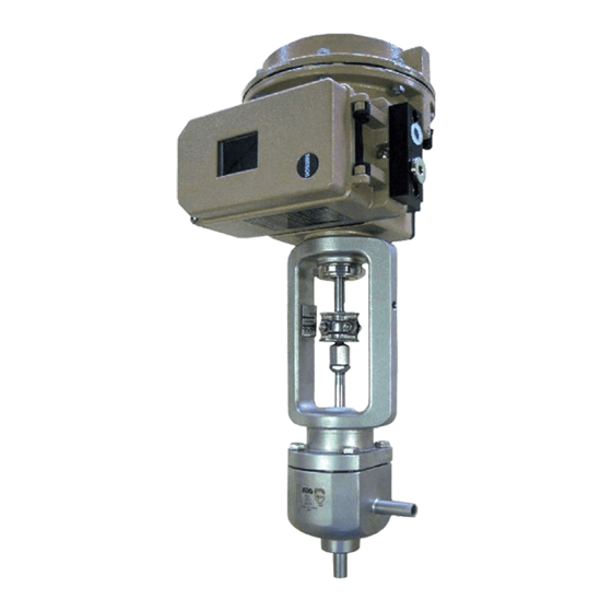
Type 3349 Aseptic Angle Valve with USP-VI diaphragm
In combination with an actuator, e.g. a SAMSON Type 3271 or
Type 3277 Pneumatic Actuator or Type 3379 Pneumatic Actuator
Edition June 2022
53-07
Advertisement
Table of Contents


Need help?
Do you have a question about the 3349 and is the answer not in the manual?
Questions and answers