Samson 3730-4 Configuration Manual
Series 3730, electropneumatic
Hide thumbs
Also See for 3730-4:
- Quick start manual ,
- Mounting and operating instructions (212 pages) ,
- Original instructions manual (128 pages)
Table of Contents

Related Manuals for Samson 3730-4


Summary of Contents for Samson 3730-4
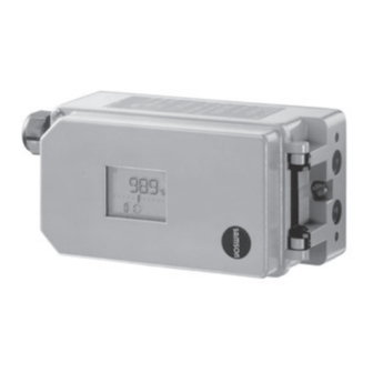
- Page 1 Series 3730 Electropneumatic Positioner Type 3730-4 Configuration and operation over PROFIBUS-PA Fig. 1 · Configuration and operation over TROVIS-VIEW (Type 3730-4) Configuration Manual KH 8384-4 EN Firmware version K 2.00/R 1.52 Edition May 2012...
- Page 2 Note concerning this Configuration Manual The rotary pushbutton on the positioner allows the Type 3730-4 Positioner to be operated and configured on site. In addition, the settings can be performed over the PROFIBUS-PA network or over the SAMSON SSP interface. The Mounting and Operating Instructions EB 8384-4 EN describe the mounting, start up and on-site operation.
- Page 3 Feature of ID number adaptation acc. to PROFIBUS PA Profile 3.02 added. It allows a Type 3785 Positioner (Profile 2.0 and Profile 3.0) to be directly replaced with a Type 3730-4 Positioner in the compatibility mode (see page 8). K 1.16 The function to suppress extended diagnostic messages allows messages for the PROFIBUS diagnosis protocol to be suppressed.
- Page 4 KH 8384-4 EN...
-
Page 5: Table Of Contents
Contents Contents Page PROFIBUS-PA communication ..... . 6 Profile ....... . . 6 Cyclic data exchange . -
Page 6: Profibus-Pa Communication
Basic device functions have been described in profiles by PNO (PROFIBUS user organiza- tion) to supplement the EN 50170 standard. The scope of functions of the Type 3730-4 Positioner is consistent with Profile 3.01 for final control elements. However, it still fulfills all obligatory functions of Profile 3.02, e.g. the auto- matic implementation on replacing old device models and versions or concerning the con- densed state according to the NAMUR Recommendation NE 107. -
Page 7: Cyclic Data Exchange
Cyclic data exchange Cyclic data exchange Cyclically transmitted parameters The following parameters that are transmitted in cyclic data transfer are marked with an as- terisk (*) in the parameter lists on page 38 onwards. POS_D Current position of the valve (discrete) 0: Not initialized 1: Closed (x <... -
Page 8: Gsd Files And Automatic Id Number Adaptation
Compatibility test Expects Type 3785 Profile 3.0 with ID number 0688 Exchanging positioners Type 3785 Profile 3.0 Type 3730-4 ID number 0688 ID number 071D Fig. 2 · Replacing positioners with automatic adaptation of the ID number KH 8384-4 EN... - Page 9 Type 3730-4 as this is the only way to access the device parameters. 1. Change the bus address of Type 3730-4 to the same bus address as Type 3785. This can be done over the PROFIBUS protocol (DEVICE_ADDRESS parameter), using the TROVIS-VIEW software or in Code 46 in the positioner.
-
Page 10: Data Exchange
Cyclic data exchange Data exchange The relationship between output and input is based on the control system/master class 1. SLOT 1 Version 1: Module = SP 0x4A or 0x82, 0x84, 0x08, 0x05 Output Byte 0 Octet 1 Octet 2 Octet 3 Octet 4 Octet 5 sign,... - Page 11 Cyclic data exchange Version 3: Module = SP, READBACK + POS_D 0xC6, 0x84, 0x86, 0x08, 0x05, 0x08, 0x05, 0x05, 0x05 Output Byte 0 Octet 1 Octet 2 Octet 3 Octet 4 Octet 5 sign, exponent exponent fraction fraction fraction fraction SP, value Status (floating point, IEEE)
- Page 12 Cyclic data exchange Version 5: Module = SP, READBACK + POS_D + CHECKBACK 0xC7, 0x84, 0x89, 0x08, 0x05, 0x08, 0x05, 0x05, 0x05, 0x0A Output Byte 0 Octet 1 Octet 2 Octet 3 Octet 4 Octet 5 sign, exponent exponent fraction fraction fraction fraction...
- Page 13 Cyclic data exchange Version 7: Module = SP + RCAS_IN, READBACK + RCAS_OUT + POS_D + CHECKBACK 0xCB, 0x89, 0x8E, 0x08, 0x05, 0x08, 0x05, 0x08, 0x05, 0x08, 0x05, 0x05, 0x05, 0x0A Output Byte 0 Octet 1 Octet 2 Octet 3 Octet 4 Octet 5 Octet 1...
-
Page 14: Integration For Pcs7 Control System
Cyclic data exchange Integration for PCS7 control system The following instructions must be observed on integrating the positioner into a Siemens Simatic S7 control system to ensure that the positioner functions properly: 1. The module in Slot 1 can be read out over the function component SFC 14 DPRD_DAT and, for example, assigned to a data module. -
Page 15: Checkback - Device Status
CHECKBACK – Device status CHECKBACK – Device status Each bit can be masked individually for cyclic communication by the class 2 master. This al- lows a targeted selection to be made from the active alarms. Byte Bit Name Description CB_FAIL_SAFE Fail-safe position: The fail-safe position has been trig- gered. - Page 16 CHECKBACK – Gerätestatus Byte Bit Name Description Control loop error: The control valve no longer follows the CB_CONTR_ERR controlled variable in the tolerable times (see error code 57 in EB 8384-4 EN). The error must be reset manually. Positioner inactive: This is set when the device is in the CB_CONTR_INACT OUT OF SERVICE mode or the output of the AO Function Block has a bad status.
-
Page 17: Measured Value Status And Valve Diagnostics
Measured value status and valve diagnostics Extended valve diagnostics – EXPERTplus The Type 3730-4 Positioner includes integrated diagnostic functions. According to the Profibus Profile 3.01 and the 'Condensed status and diagnostic messages' extension, the generated alarms can be classified and summarized (see section 5.5, page 29). -
Page 18: Classification Of The Status Alarms And The Condensed State
Measured value status and valve diagnostics Classification of the status alarms and the condensed state Note: The following description only applies to positioners configured corresponding to the Profile 3.01 with the 'Condensed status and diagnostic messages' extension (set in the COND_STATUS_ DIAG parameter of the Physical Block). - Page 19 Measured value status and valve diagnostics The condensed state is displayed in the engineering tool and on the positioner display (see table below). Condensed state Engineering tool/ Positioner display Status alarm TROVIS-VIEW (version 3.40 and higher) No message, OK green tEsting , tunE or tEst Function check orange...
- Page 20 Measured value status and valve diagnostics Fig. 3 · Status and diagnostic alarms KH 8384-4 EN...
-
Page 21: Status Alarm According To Profile 3.01
Measured value status and valve diagnostics Status alarm according to Profile 3.01 Value (hex) Status alarm acc. to Fault/diagnostic alarm Profile 3.01 Operational errors Device not initialized BAD_OUT_OF_SERVICE 0x1C Solenoid valve active GOOD_NON_SPECIFIC 0x80 Total travel exceeded 0xA4 GOOD_MAINT_REQ Control loop error 0x4A GOOD_MAINT_REQ Zero point error... - Page 22 Measured value status and valve diagnostics Value (hex) Status alarm acc. to Fault/diagnostic alarm Profile 3.01 Test calculation 0x0C BAD_DEVICE_FAILURE Program loading error BAD_DEVICE_FAILURE 0x0C Data errors Control parameter GOOD_MAINT_REQ 0xA4 Potentiometer parameter 0xA4 GOOD_MAINT_REQ Calibration error 0xA4 GOOD_MAINT_REQ Internal device error 0x0C BAD_DEVICE_FAILURE General parameters...
- Page 23 Status alarm according to Profile 3.01 Value (hex) Status alarm acc. to Fault/diagnostic alarm Profile 3.01 Friction Much higher over whole range 0x80 GOOD_NON_SPECIFIC Much lower over whole range 0x80 GOOD_NON_SPECIFIC Much higher over partial range GOOD_NON_SPECIFIC 0x80 Much lower over partial range 0x80 GOOD_NON_SPECIFIC Much higher over whole range (TEST)
- Page 24 Measured value status and valve diagnostics Value (hex) Status alarm acc. to Fault/diagnostic alarm Profile 3.01 Observing end position Zero point shift monotonously downwards, average value above 0x80 GOOD_NON_SPECIFIC reference lines Zero point shift monotonously upwards, average value above 0x80 GOOD_NON_SPECIFIC reference lines Zero point alternating, average value above reference lines...
-
Page 25: Status Alarms According To Profile 3.01 Condensed Status
Measured value status and valve diagnostics Value (hex) Status alarm acc. to Fault/diagnostic alarm Profile 3.01 Function activated Initialization active 0x80 GOOD_NON_SPECIFIC Diagnostic function activated GOOD_NON_SPECIFIC 0x80 Status alarms according to Profile 3.01 Condensed Status Classified Default setting acc. to Pro- Fault/diagnostic alarm Diagnosis file 3.01 Condensed Status... - Page 26 Measured value status and valve diagnostics Classified Default setting acc. to Pro- Fault/diagnostic alarm Diagnosis file 3.01 Condensed Status Initialization running 0xA4 GOOD_MAINT_REQ • – Hardware error x signal 0xA8 GOOD_MAIN_DEMANDED • DIA_MEASUREMENT i/p converter 0x24 BAD_MAINT_ALARM • DIA_HW_ELECTR Hardware 0x24 BAD_MAINT_ALARM DIA_HW_ELECTR •...
- Page 27 Status alarms according to Profile 3.01 Condensed Status Classified Default setting acc. to Pro- Fault/diagnostic alarm Diagnosis file 3.01 Condensed Status Perhaps bias reduced (TEST) 0x80 GOOD_NON_SPECIFIC • – Perhaps bias increased (TEST) 0x80 GOOD_NON_SPECIFIC • – Working at full capacity 0x80 GOOD_NON_SPECIFIC •...
- Page 28 Status alarms according to Profile 3.01 Condensed Status Classified Default setting acc. to Pro- Fault/diagnostic alarm Diagnosis file 3.01 Condensed Status Perhaps larger than in original state 0x80 GOOD_NON_SPECIFIC • – (TEST) Perhaps larger than original state 0x80 GOOD_NON_SPECIFIC • –...
-
Page 29: Standard Diagnostics With Profibus-Dp Protocol
Measured value status and valve diagnostics Classified Default setting acc. to Pro- Fault/diagnostic alarm Diagnosis file 3.01 Condensed Status Mostly max. opening 0x80 GOOD_NON_SPECIFIC • – Temperature monitoring Lower limit exceeded 0x80 GOOD_NON_SPECIFIC – • Higher limit exceeded 0x80 GOOD_NON_SPECIFIC –... - Page 30 If, however, the DIAG.ext bit is set to 0, the existing data are treated as status information by the system. For the Type 3730-4 Positioner, this behavior can be determined by the FEATURE_SELECT parameter. By selecting the option “DIA_MAINTENANCE_ALARM sets DIAG_EXT bit“, the DIAG_EXT bit is set when the DIA_MAINTENANCE_ALARM bit has been...
- Page 31 Standard diagnostics with PROFIBUS-DP protocol The default setting causes the positioner to provide a manufacturer-specific diagnosis of 26 bytes and a diagnosis of 14 bytes according to Profile 3.01. Octet Explanation Note 0…7 0…7 0…7 Standard slave diagnostics 0…7 0…7 0…7 0…7 0…7...
- Page 32 Standard diagnostics with PROFIBUS-DP protocol Explanation Octet Note 4…7 Reserved in Profile 3.01 0…6 Reserved in Profile 3.01 EXTENSION_AVAILABLE (further diagnostic information available) Device not initialized Solenoid valve active Total valve travel limit exceeded (see Code 24) Control loop (see Code 57) Zero point (see Code 58) Autocorrection (see Code 59) Fatal error (see Code 60)
- Page 33 Standard diagnostics with PROFIBUS-DP protocol Explanation Octet Note No emergency mode (see Code 76) Program load error (see Code 77) Options parameter (see Code 78) Info parameter (see Code 75) Data memory (see Code 66) Control calculation (see Code 67) PA parameter (see Code 74) Diagnostic parameter (see Code 80) Reset communication controller...
- Page 34 Standard diagnostics with PROFIBUS-DP protocol Explanation Octet Note Friction: Lower over partial range Friction: Higher whole range (TEST) Friction: Lower whole range (TEST) Friction: Higher over partial range (TEST) Friction: Lower over partial range (TEST) Leakage in pneumatics: Perhaps existing (TEST) Leakage in pneumatics: Perhaps existing Leakage in pneumatics: Too large (TEST) Leakage in pneumatics: Perhaps too large...
- Page 35 Measured value status and valve diagnostics Explanation Octet Note Zero point shift alternating, average value below reference lines Attachment between positioner and valve: Travel transmission not optimal (TEST) Attachment between positioner and valve: Perhaps loose Attachment between positioner and valve: Perhaps working range limited Attachment between positioner and valve: Perhaps loose (TEST) Working range: Mostly near closing position Working range: Mostly near max.
-
Page 36: Acyclic Data Exchange
The acyclic data exchange complying to DP-V1 with a master class 2 (MS2) is mainly used for commissioning, parameter settings and for diagnostic purposes. The DD (Device Description) file can be downloaded from the SAMSON Internet site (www.samson.de) to configure parameters in Type 3730-4 Positioner over Siemens PDM (Process Device Manager). -
Page 37: Partial Stroke Testing Over Dp-V0
Partial stroke testing over DP-V0 Partial stroke testing over DP-V0 The partial stroke test (PST) can be started in the following ways: Start over binary Start with auto test Start over Operating mode Test mode PST input time reference variable PST MAN •... -
Page 38: Parameter Lists
Parameterlisten Parameter lists Legend The parameter index is written in parentheses after the parameter description in the following tables. Class of memory: Static parameter Dynamic parameter Non-volatile parameter Read/write Read capability capability: Write capability (access) Supported O/S (out of service) mode modes: MAN mode AUTO mode... -
Page 39: Physical Block, Slot 0 · Profile-Specific Parameters
Any desired text to describe the application. The text is saved in the field device. • Max. 32 characters, [no text] DEVICE_CERTIFICATION (33) Storage class: – · Read capability (r) Certification · Specifies whether explosion protection certification is available for Type 3730-4. DEVICE_ID (27) Storage class: – · Read capability (r) Positioner’s model number DEVICE_INSTAL_DATE (38) Storage class: N ·... - Page 40 Physical Block, Slot 0 · Profile-specific parameters DEVICE_MAN_ID (26) Storage class: – · Read capability (r) Manufacturer of the positioner DEVICE_MESSAGE (37) Storage class: S · Read/write capability (r/w) · Supported modes: ALL Any desired text. The text is saved in the field device. •...
- Page 41 Physical Block, Slot 0 · Profile-specific parameters Byte According to PA V3.01 Description DIA_MAINTENANCE_ALARM Device error exists DIA_MAINTENANCE_DEMANDED Maintenance demanded DIA_FUNCTION_CHECK Device performing a function check or it is in simulation or in MODE_LO DIA_INV_PRO_COND The current process conditions do not allow a valid calculation of values 4…7 –...
- Page 42 Physical Block, Slot 0 · Profile-specific parameters Byte Description Emergency mode · No error (Code 76) Program loading error (Code 77) Options parameter (Code 78) Info parameter (Code 75) Data memory (Code 66) Test calculation (Code 67) PA parameters (Code 74) Diagnostic parameters (Code 80) Reset communication controller...
- Page 43 Physical Block, Slot 0 · Profile-specific parameters • 2712 (0x0A98) · Resets the bus address to the default value of 126. The positioner restarts after the reset is performed. The bus address is not reset when the identification parameters are reset. Note: The bus address can only be reset using this command in firmware version K 1.11 and higher.
- Page 44 Physical Block, Slot 0 · Profile-specific parameters FEATURE (42) Storage class: – · Read capability (r) Optional existence and state of the feature integrated into the device Supported/enabled (Note: The structure for supported and enabled are identical!) • 0 = Not supported/not enabled •...
- Page 45 Physical Block, Slot 0 · Profile-specific parameters MODE_BLK (22) Storage class: – · Read capability (r) Current mode of the Physical Block SOFTWARE_REVISION (24) Storage class: – · Read capability (r) Firmware version (communication ® Code 48 F0 /control® Code 43) ST_REV (17) Storage class: –...
- Page 46 Physical Block, Slot 0 · Profile-specific parameters Index and parameter assignment: Physical Block, Slot 0 · Profile-specific parameters Index Parameter Index Parameter BLOCK_OBJ DIAGNOSIS_MASK ST_REV DIAGNOSIS_MASK_EXT TAG_DESC DEVICE_CERTIFICATION STRATEGY WRITE_LOCKING ALERT_KEY FACTORY_RESET TARGET_MODE DESCRIPTOR MODE_BLK DEVICE_MESSAGE ALM_SUM DEVICE_INSTAL_DATE SOFTWARE_REVISION LOCAL_OP_ENA HARDWARE_REVISION IDENT_NUMBER_SELECTOR DEVICE_MAN_ID...
-
Page 47: Physical Block, Slot 0 · Manufacturer-Specific Parameters
• 3785: 3785 Profile 2 • 071D: 3785 Profile 3 • 0688: 3730-4 Profile 3.01 CONDENSED_STATUS (133) Storage class: – · Read capability (r) Condensed state according to NAMUR CONFIG_BINARY_INPUT_2 (59) Storage class: S · Read/write capability (r/w) · Supported modes: ALL Configuration of the second binary input •... - Page 48 Physical Block, Slot 0 · Manufacturer-specific parameters • 7 · Actively closed – Diagnosis leakage sensor/CB_ADD_INPUT Solenoid valve – DI2 · A leakage sensor is operated at the input as actively closed. This information can be analyzed with Function Block DI2. Additionally, the state of the internal solenoid valve is also transmitted cyclically with CHECKBACK (CB_ADD_INPUT).
- Page 49 Physical Block, Slot 0 · Manufacturer-specific parameters DATALOGGER_DS_15 (125) Storage class: – · Read capability (r) Test function: Data logger – Data set 1 to 14 Element Parameter name SOLLWERT_W_1 (reference variable w - data set 1) ISTWERT_X_1 (valve position x - data set 1) STELLSIGNAL_Y_1 (drive signal y - data set 1) REGELABWEICH_E_1 (setpoint deviation e - data set 1) ZEIT_T_1 (time t - data set 1)
- Page 50 Physical Block, Slot 0 · Manufacturer-specific parameters DIAGNOSIS_DATA_1 (131) Storage class: – · Read capability (r) Diagnostic alarms • 0x01 Inconsistent data memory • 0x02 Potentiometer parameter • 0x04 Calibration parameter • 0x08 General parameter • 0x10 Interal device error •...
- Page 51 Physical Block, Slot 0 · Manufacturer-specific parameters Byte Description Leakage in pneumatics: Perhaps too large Restriction of working range: Downwards Restriction of working range: Upwards Restriction of working range: Modification impossible Dynamic stress factor > 90 % Inner leakage (shut-off): Perhaps existing Inner leakage (shut-off): Perhaps larger than in original state (TEST) Inner leakage (shut-off): Perhaps larger than original state External leakage: Perhaps soon expected...
- Page 52 Physical Block, Slot 0 · Manufacturer-specific parameters DIAGNOSIS_HW (130) Storage class: – · Read capability (r) Diagnostic alarms • 0x01 x signal • 0x02 i/p converter • 0x04 Hardware error • 0x08 Data memory • 0x10 Test calculation • 0x20 Program loading error DIAGNOSIS_INIT_1 (128) Storage class: –...
- Page 53 Physical Block, Slot 0 · Manufacturer-specific parameters DL_TRIGGER_SELECT_BIN (136) Storage class: S · Read/write capability (r/w) · Supported modes: ALL Binary input for triggerung in data logger (can be selected with firmware version K 1.11 or higher) • 0 · Binary input 1 •...
- Page 54 Physical Block, Slot 0 · Manufacturer-specific parameters FEATURE_SELECT (64) Storage class: S · Read/write capability (r/w) · Supported modes: ALL Coded bitwise, therefore more than one alarm possible at one time Bit: 0 = false · 1 = true Byte Description BAD_DEVICE_FAILURE sets DIAG_EXT-Bit ·...
- Page 55 Physical Block, Slot 0 · Manufacturer-specific parameters FST_SW_1 (142) to FST_SW_4 (145) Storage class: – · Read capability (r) Tests MAN: Full stroke test (FST) – Reference variable data set 1 to 4 • FST_SW_1: Data set 1 (measured points 1 to 25) •...
- Page 56 Physical Block, Slot 0 · Manufacturer-specific parameters HISTOGRAMM_E_LANG (67) Storage class: – · Read capability (r) Statistical information AUTO: Structure for long-term setpoint deviation histogram Element Parameter name E_INTERVAL_VALUE_0 (setpoint deviation interval 0) … E_INTERVAL_VALUE_11 (setpoint deviation interval 11) E_AVERAGE (average value e for long-term) NUMBER_MESS_POINTS (number of measuring points) DEVIATION_MIN (min.
- Page 57 Physical Block, Slot 0 · Manufacturer-specific parameters HISTOGRAMM_Z_KURZ (71) Storage class: – · Read capability (r) Statistical information AUTO: Structure for short-term cycle counter histogram Element Parameter name Z_INTERVAL_VALUE_0 (cycle counter interval 0) … Z_INTERVAL_VALUE_12 (cycle counter interval 12) Z_AVERAGE (average value z for short-term) HISTOGRAMM_Z_LANG (68) Storage class: –...
- Page 58 Physical Block, Slot 0 · Manufacturer-specific parameters HYSTERESE_KURZ (76) Storage class: – · Read capability (r) Statistical information AUTO: Structure for drive signal diagram hysteresis in short-term monitoring Element Parameter name STELLSIGNAL_0 (drive signal 0) VENTILSTELLUNG_0 (valve position 0) … STELLSIGNAL_9 (drive signal 9) VENTILSTELLUNG_9 (valve position 9) HYSTERESE_LANG (75)
- Page 59 Physical Block, Slot 0 · Manufacturer-specific parameters PST_SS_1 (101) and PST_SS_2 (102) Storage class: – · Read capability (r) Tests MAN: Partial stroke test (PST) – Drive signal data set 1 and 2 PST_SW_1 (97) to PST_SW_4 (100) Storage class: – · Read capability (r) Tests MAN: Partial stroke test (PST) –...
- Page 60 Physical Block, Slot 0 · Manufacturer-specific parameters STAT_KENNLINIE_VS_1 (85) to STAT_KENNLINIE_VS_4 (88) Storage class: – · Read capability (r) Tests MAN: Static characteristic – Valve position data set 1 to 4 • STAT_KENNLINIE_VS_1: data set 1 (measuring points 1 to 25) •...
- Page 61 Physical Block, Slot 0 · Manufacturer-specific parameters STATIONAER_KURZ_RP (74) Storage class: – · Read capability (r) Statistical information AUTO: Structure for drive signal diagram steady-state in short-term monitoring. Ring buffer values, containing drive signal and valve position Element Parameter STELLSIGNAL_0 (drive signal 0) VENTILSTELLUNG_0 (valve position 0) …...
- Page 62 Physical Block, Slot 0 · Manufacturer-specific parameters Index Parameter Index Parameter ET_ENDLAGE PST_ZEIT_2 STAT_REF_VS PST_ZEIT_3 STAT_AGAIN_VS PST_ZEIT_4 STAT_STELLSIGNAL DATALOGGER_DS_1 HYS_STELLSIGNAL DATALOGGER_DS_2 STAT_KENNLINIE_R DATALOGGER_DS_3 STAT_KENNLINIE_VS_1 DATALOGGER_DS_4 STAT_KENNLINIE_VS_2 DATALOGGER_DS_5 STAT_KENNLINIE_VS_3 DATALOGGER_DS_6 STAT_KENNLINIE_VS_4 DATALOGGER_DS_7 STAT_KENNLINIE_SW_1 DATALOGGER_DS_8 STAT_KENNLINIE_SW_2 DATALOGGER_DS_9 STAT_KENNLINIE_SW_3 DATALOGGER_DS_10 STAT_KENNLINIE_SW_4 DATALOGGER_DS_11 PST_VS_1 DATALOGGER_DS_12 PST_VS_2 DATALOGGER_DS_13...
-
Page 63: Ao Function Block, Slot 1 · Profile-Specific Parameters
AO Function Block, Slot 1 · Profile-specific parameters Index Parameter Index Parameter ACTIVE_IDENT_NUMBER FST_E_1 FST_VS_1 FST_E_2 FST_VS_2 FST_E_3 FST_VS_3 FST_E_4 FST_VS_4 FST_ZEIT_1 FST_SW_1 FST_ZEIT_2 FST_SW_2 FST_ZEIT_3 FST_SW_3 FST_ZEIT_4 FST_SW_4 HISTOGRAMM_X_LANG2 FST_SS_1 CONFIG_DI_1 FST_SS_2 CONFIG_DI_2 8.1.2 AO Function Block, Slot 1 · Profile-specific parameters ALERT_KEY (20) Storage class: S ·... - Page 64 AO Function Block, Slot 1 · Profile-specific parameters CHECK_BACK_MASK (50) Storage class: – · Read capability (r) Defines the supported status bits in CHECK_BACK Bit = 0: Status not supported Bit = 1: Status supported CHECK_BACK_OPT (65) Storage class: S · Read/write capability (r/w) · Supported modes: ALL This alarm does not apply for acyclic access Defines the support of the status bit in CHECK_BACK for cyclic data exchange •...
- Page 65 AO Function Block, Slot 1 · Profile-specific parameters IN_CHANNEL (37) Storage class: S · Read/write capability (r/w) · Supported modes: ALL Assignment between the Transducer Block and the Function Block • 0 · Not active • 0x013A · Active (FEEDBACK_VALUE is written to READBACK) INCREASE_CLOSE (52) Storage class: S ·...
- Page 66 AO Function Block, Slot 1 · Profile-specific parameters POS_D* (47) Storage class: – · Read capability (r) Current position of the valve (discrete) • 0 · Not initialized • 1 · Closed (x < 0.5 %) • 2 · Open (x > 99.5 %) •...
- Page 67 AO Function Block, Slot 1 · Profile-specific parameters SP (25) Storage class: S · Read/write capability (r/w) · Supported modes: ALL Upper limit of the reference variable • Value and range from PV_SCALE ±10 %, [100 %] Note: This value must be adapted correspondingly if the scale end setting is changed in PV_SCALE parameter.
-
Page 68: Ao Transducer Block, Slot 1 · Profile-Specific Parameters
AO Transducer Block, Slot 1 · Profile-specific parameters Index and parameter assignment: AO Transducer Block, Slot 1 · Profile-specific parameters Index Parameter Index Parameter BLOCK_OBJ FSAFE_TIME ST_REV FSAFE_TYPE TAG_DESC FSAFE_VALUE STRATEGY RCAS_OUT ALERT_KEY POS_D TARGET_MODE SETP_DEVIATION MODE_BLK CHECK_BACK ALM_SUM CHECK_BACK_MASK BATCH SIMULATE INCREASE_CLOSE... - Page 69 AO Transducer Block, Slot 1 · Profile-specific parameters ACT_STROKE_TIME_INC (90) Storage class: – · Read capability (r) Specifies the minimum transit time to reach OPEN position [s] (Code 40) The minimum transit time to reach OPEN (100 % position) position is the actual time in seconds that the system (consisting of positioner, actuator and valve) needs to move through the rated travel range/an- gle of rotation to open the valve (measured during initialization).
- Page 70 • 3 · User-defined (currently not supported) • 4 · SAMSON control butterfly valve linear • 5 · SAMSON control butterfly valve equal percentage • 6 · Vetec rotary plug valve linear • 7 · Vetec rotary plug valve equal percentage...
- Page 71 AO Transducer Block, Slot 1 · Profile-specific parameters MODE_BLK (86) Storage class: – · Read capability (r) Current mode of positioner POSITIONING_VALUE (137) Storage class: – · Read capability (r) Current positioning value Unit of OUT_SCALE RATED_TRAVEL (112) Storage class: S · Read/write capability (r/w) · Supported modes: ALL Specifies the rated travel [mm] or rotational angle [degrees] of the valve •...
- Page 72 AO Transducer Block, Slot 1 · Profile-specific parameters • 35 to 39 · – • 40 · Reset “x signal“ • 41 · Reset “i/p converter“ • 42 · Reset “Hardware“ • 43 · Reset “Control parameter“ • 44 · Reset “Potentiometer parameter“ •...
- Page 73 AO Transducer Block, Slot 1 · Profile-specific parameters • 7 · Calibration sequence mixed up • 8 to10 · – • 11 · Timeout • 12 · Proportional range restricted too much • 13 · Rated travel or transmission incorrectly selected •...
- Page 74 AO Transducer Block, Slot 1 · Profile-specific parameters SETP_CUTOFF_INC (119) Storage class: S · Read/write capability (r/w) · Supported modes: ALL Final position w > (Code 15) If the reference variable exceeds the entered value, the valve moves towards the final position which corresponds to 100 % reference variable.
- Page 75 AO Transducer Block, Slot 1 · Profile-specific parameters TRAVEL_LIMIT_LOW (127) Storage class: S · Read/write capability (r/w) · Supported modes: ALL Travel/angle lower limit [% of PV_SCALE] (Code 10) Limitation of the travel/angle of rotation downwards to the entered value. The characteristic is not adapted.
- Page 76 AO Transducer Block, Slot 1 · Profile-specific parameters VALVE_TYPE (141) Storage class: S · Read/write capability (r/w) · Supported modes: ALL Type of valve • 0 · Valve with straight-moving plug • 1 · Valve with rotary moving plug (part-turn) •...
-
Page 77: Ao Transducer Block, Slot 1 · Manufacturer-Specific Parameters
• 3785: 3785 Profile 2 • 071D: 3785 Profile 3 • 0688: 3730-4 Profile 3.01 AUTOSTART_HYS (194) Storage class: S · Read/write capability (r/w) · Supported modes: ALL Indicates the minimum interval between the hysteresis tests (EXPERTplus) BLOCKING_POSITION (166) Storage class: S · Read/write capability (r/w) · Supported modes: ALL CHARACT_TYPE (173) Storage class: S ·... - Page 78 AO Transducer Block, Slot 1 · Manufacturer-specific parameters DATALOGGER (185) Storage class: – · Read capability (r) Structure of read and write parameters of the data logger (EXPERTplus) Element Parameter DATALOGGER_SELECT (selection for data logger) TRIGGER_SELECT (trigger status) SAMPLE_RATE (scan rate) START_VALUE (trigger value) LOGGING_LIMIT PRETRIGGER_TIME...
- Page 79 AO Transducer Block, Slot 1 · Manufacturer-specific parameters DEVICE_CHARACT (202) and DEVICE_CHARACT_2 (231) Storage class: S · Read/write capability (r/w) · Supported modes: ALL Structure of the device properties Element Parameter Actuator effective area Type of actuator Attachment Lower signal pressure range Upper signal pressure range Supply pressure Booster...
- Page 80 AO Transducer Block, Slot 1 · Manufacturer-specific parameters DIAG_TESTINFO (201) Storage class: – · Read capability (r) Info parameter concerning an active diagnostic test running (EXPERTplus) 0 · d1 Drive signal diagram steady-state 2 · d2 Drive signal diagram hysteresis 4 ·...
- Page 81 AO Transducer Block, Slot 1 · Manufacturer-specific parameters • 5 · Start partial stroke test • 6 · Stop partial stroke test • 7 · Start all tests automatically in sequence • 8 · Stop tests • 9 · Start drive signal test steady-state •...
- Page 82 AO Transducer Block, Slot 1 · Manufacturer-specific parameters EVENT_LOGGING_1 (190) and EVENT_LOGGING_2 (191) Storage class: – · Read capability (r) Data sets 1/2 of the event logging (EXPERTplus) Element Parameter MESSAGES_0…15 (alarms 0…15) ELAPSED_HOURS_METER_0…15 (time stamp of recorded alarms 0…15) …...
- Page 83 AO Transducer Block, Slot 1 · Manufacturer-specific parameters • FST_MEAS_DATA1…3_DEAD_TI_FALL • FST_MEAS_DATA1…3_T63_FALLING • FST_MEAS_DATA1…3_T98_FALLING • FST_MEAS_DATA1…3_RISE_TI_FALLING • FST_MEAS_DATA1…3_SETTL_TI_FALLING FST_CANCEL_CONDITIONS (226) Storage class: S · Read/write capability (r/w) · Supported modes: ALL Cancelation conditions of the full stroke test (FST) • FST_CANCEL_COND_MAX_TEST_DURA: Maximum test duration (user-defined) •...
- Page 84 AO Transducer Block, Slot 1 · Manufacturer-specific parameters FST_TEST_STATUS_1 (228) to FST_TEST_STATUS_3 (230) Storage class: – · Read capability (r) Status of performed full stroke tests (FST) HISTOGRAMM_E_ABTASTRATE (200) Storage class: S · Read/write capability (r/w) · Supported modes: ALL Scan rate for setpoint deviation histogram for short-term monitoring (EXPERTplus) HISTOGRAMM_X_ABTASTRATE (199) Storage class: S ·...
- Page 85 AO Transducer Block, Slot 1 · Manufacturer-specific parameters PRESSURE_LIMIT (177) Storage class: S · Read/write capability (r/w) · Supported modes: ALL Pressure limit (Code 16) • 1 · Off • 2 · 3.7 bar • 3 · 2.4 bar • 4 · 1.4 bar PST_ANALYSIS_1 (213) to PST_ANALYSIS_3 (215) Storage class: –...
- Page 86 AO Transducer Block, Slot 1 · Manufacturer-specific parameters • PST_CANCEL_COND_ACTIV_MAX_TIME (activation 'Max. breakaway time') • PST_CANCEL_COND_MAX_BREAK_TIME (max. breakaway time) • PST_CANCEL_COND_ACTIVE_TIME_REACH (activation 'Allowed time to reach PST target') • PST_CANCEL_COND_TIME_REACH (allowed time to reach PST target) PST_DISPLAY (218) Storage class: – · Read capability (r) Information on partial stroke test (PST) •...
- Page 87 AO Transducer Block, Slot 1 · Manufacturer-specific parameters PST_TEST_STATUS_1 (219) to PST_TEST_STATUS_3 (221) Storage class: – · Read capability (r) Status of partial stroke tests (PST) • PST_TEST_STAT1...3_TEST_START (test start) • PST_TEST_STAT1...3_no_test_avail (no test available) • PST_TEST_STAT1...3_X_CANCEL (x cancellation) • PST_TEST_STAT1...3_Y_CANCEL (y cancellation) •...
- Page 88 AO Transducer Block, Slot 1 · Manufacturer-specific parameters • 29 Reset 'Travel histogram x - short-term monitoring' • 30 Reset 'Setpoint deviation histogram e - short-term monitoring' • 31 Reset 'Cycle counter histogram - short-term monitoring' • 32 Reset 'Drive signal diagram hysteresis - short-term monitoring' •...
- Page 89 AO Transducer Block, Slot 1 · Manufacturer-specific parameters STARTUP_PARA (207) Storage class: S · Read/write capability (r/w) · Supported modes: ALL Start-up parameters • TRANS1_INIT_METHOD (initialization method (MAX, NOM, MAN, SUB) • TRANS1_MOVING_DIRECTION (direction of action) • TRANS1_LIN_TYPE (type of characteristic) •...
- Page 90 AO Transducer Block, Slot 1 · Manufacturer-specific parameters TIME_63_FALLING TIME_98_RISING TIME_98_FALLING STEP_PROGRESS RISE_TIME_FALLING SETTLING_TIME_FALLING RISE_TIME_RISING SETTLING_TIME_RISING DURATION_OF_TEST TESTINFO STEP_RESPONSE_RW (189) Storage class: S · Read/write capability (r/w) · Supported modes: ALL Parameters for step response (EXPERTplus) Element Parameter STEPSTART STEPEND STEP_SAMPLE_RATE RAMPE_UP RAMPE_DOWN...
- Page 91 AO Transducer Block, Slot 1 · Manufacturer-specific parameters • 4 · Tight-closing of the valve (final position w <, Code 14) • 5 · Valve fully open (final position w >, Code 15) • 7 · Fail-safe position active • 255 · Normal operation TRAVEL_LIMIT_LOW_ON (168) Storage class: S ·...
- Page 92 AO Transducer Block, Slot 1 · Manufacturer-specific parameters Index and parameter assignment: AO Transducer Block, Slot 1 · Manufacturer-specific parameters Index Parameter Index Parameter PIN_POSITION EVENT_LOGGING_1 INIT_METHOD EVENT_LOGGING_2 SUB_MODE_INIT ENHANCED_DIAG_CMD DEVICE_INIT_STATE ELAPSED_HOURS_METERS MOVING_DIRECTION AUTOSTART_HYS CLOSING_DIRECTION DIAGNOSE_LEVEL BLOCKING_POSITION NO_OF_ZERO_POINT_ADJ SELF_CALIB_WARNING ZERO_POINT_LIMIT TRAVEL_LIMIT_LOW_ON COUNTER_INIT_START TRAVEL_LIMIT_UP_ON...
-
Page 93: Di1/2 Function Block, Slot 2/3 · Profile-Specific Parameters
DI1/2 Function Block, Slot 2/3 · Profile-specific parameters Index Parameter Index Parameter PST_DISPLAY FST_CANCEL_CONDITIONS PST_TEST_STATUS_1 FST_DISPLAY PST_TEST_STATUS_2 FST_TEST_STATUS_1 PST_TEST_STATUS_3 FST_TEST_STATUS_2 FST_ANALYSIS_1 FST_TEST_STATUS_3 FST_ANALYSIS_2 DEVICE_CHARACT_2 FST_ANALYSIS_3 STAT_KENNLINIE_RW_2 FST_SETTINGS SELF_CALIB_STATUS_2 8.3.1 DI1/2 Function Block, Slot 2/3 · Profile-specific parameters ALERT_KEY (20) Storage class: S · Read/write capability (r/w) · Supported modes: ALL Identification number of the plant section •... - Page 94 DI1/2 Function Block, Slot 2/3 · Profile-specific parameters CHANNEL (30) Storage class: S · Read/write capability (r/w) · Supported modes: ALL Connection of the Function Block with the Transducer Block DI1: 0 · Not active 780 · Active DI2: 0 · Not active 524 ·...
- Page 95 DI1/2 Function Block, Slot 2/3 · Profile-specific parameters ST_REV (17) Storage class: – · Read capability (r) Revision level of static data STRATEGY (19) Storage class: S · Read/write capability (r/w) · Supported modes: ALL Grouping to allow faster processing of blocks •...
- Page 96 DI1/2 Function Block, Slot 2/3 · Profile-specific parameters Index and parameter assignment: DI1/2 Function Block, Slot 2/3 · Profile-specific parameters Index Parameter Index Parameter BLOCK_OBJECT BATCH ST_REV OUT_D TAG_DESC CHANNEL STRATEGY INVERT ALERT_KEY FSAFE_TYPE TARGET_MODE FSAFE_VAL_D MODE_BLK SIMULATE ALM_SUM KH 8384-4 EN...
-
Page 97: Di1/2 Transducer Block, Slot 2/3 · Profile-Specific Parameters
DI1/2 Transducer Block, Slot 2/3 · Profile-specific parameters 8.3.2 DI1/2 Transducer Block, Slot 2/3 · Profile-specific parameters ALERT_KEY (64) Storage class: S · Read/write capability (r/w) · Supported modes: ALL Identification number of the plant section • [0] ALM_SUM (67) Storage class: –... - Page 98 DI1/2 Transducer Block, Slot 2/3 · Profile-specific parameters ST_REV (61) Storage class: S · Read capability (r) Revision level of static data STRATEGY (63) Storage class: S · Read/write capability (r/w) · Supported modes: ALL Grouping to allow faster processing of blocks •...
- Page 99 KH 8384-4 EN...
- Page 100 SAMSON AG · MESS- UND REGELTECHNIK Weismüllerstraße 3 · 60314 Frankfurt am Main · Germany Phone: +49 69 4009-0 · Fax: +49 69 4009-1507 KH 8384-4 EN Internet: http://www.samson.de...
Need help?
Do you have a question about the 3730-4 and is the answer not in the manual?
Questions and answers