Samson 3730 Series Mounting And Operating Instructions
Electropneumatic positioner
Hide thumbs
Also See for 3730 Series:
- Mounting and operating instructions (220 pages) ,
- Operating instructions manual (120 pages) ,
- Mounting and operating instructions (140 pages)

Related Manuals for Samson 3730 Series


Summary of Contents for Samson 3730 Series
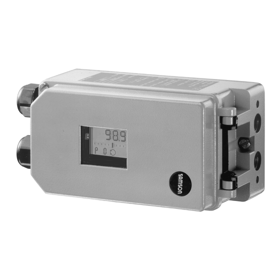
- Page 1 Series 3730 Type 3730-1 Electropneumatic Positioner Fig. 1 · Type 3730-1 Mounting and Operating Instructions EB 8384-1 EN (1300-1610) Firmware version 2.12 Edition December 2014...
-
Page 2: Table Of Contents
Contents Contents Page Important safety instructions ..... . 6 Article code ......7 Design and principle of operation. - Page 3 Contents Faults ....... . . 43 Zero calibration ......43 Reset .
- Page 4 EB 8384-1 EN...
- Page 5 Revision in positioner firmware Revision in positioner firmware compared to the previous version Previous version 2.02 2.10 New reset function in Code P0, refer to section 7.8 New manual adjustment function in Code P14, refer to section 7.9 2.10 2.11 Internal modifications 2.11 2.12...
-
Page 6: Important Safety Instructions
Important safety instructions Important safety instructions For your own safety, follow these instructions concerning the mounting, start-up and opera- tion of the positioner: The positioner is to be mounted, started up or operated only by trained and experienced personnel familiar with the product. According to these Mounting and Operating Instructions, trained personnel refers to individuals who are able to judge the work they are assigned to and recognize possible dangers due to their specialized training, their knowledge and experience as... -
Page 7: Article Code
Article code Article code Article code Type 3730-1 x x 0 0 0 0 0 0 0 x 0 0 x 0 0 0 With LCD, autotune 4 to 20 mA reference variable, two software limit switches Explosion protection Without ATEX: II 2G Ex ia IIC T6 Gb, II 2D Ex tb IIIC T 80 °C Db IP 66 FM/CSA: Class I, Zone 0 AEx ia IIC;... -
Page 8: Design And Principle Of Operation
Design and principle of operation the 4 to 20 mA DC control signal (reference Design principle variable) after it has been converted by the operation A/D converter (4). In case of a system deviation, the operation The electropneumatic positioner is mounted of the i/p converter (6) is changed so that to pneumatic control valves and is used to the actuator (1) is filled or vented via the... - Page 9 Design and principle of operation Air capacity booster Control valve Pressure regulator Travel sensor Flow regulator PD controller 10 Volume restriction A/D converter 11 Limit switches Microcontroller 12 Display i/p converter Fig. 2 · Functional diagram EB 8384-1 EN...
-
Page 10: Technical Data
Design and principle of operation Technical data Positioner (technical data in test certificates additionally apply for explosion-protected devices) Direct attachment to Type 3277: 3.6 to 30 mm Travel, adjustable Attachment acc. to IEC 60534-6: 3.6 to 200 mm or 24° to 100° with rotary actuators Adjustable within the initialized travel/angle of rotation;... - Page 11 Design and principle of operation Positioner (technical data in test certificates additionally apply for explosion-protected devices) ATEX Type 3730-11 II 2G Ex ia IIC T6 Gb, II 2D Ex tb IIIC T80°C Db IP66 Type 3730-18 II 3G Ex nA II T6, II 3G Ex ic IIC T6, II 3D Ex tc IIIC T80°C IP66 Ex ia IIC T6;...
-
Page 12: Attachment To The Control Valve - Mounting Parts And Accessories
– mounting parts and accessories The positioner can be attached either di- rectly to a SAMSON Type 3277 Actuator or according to IEC 60534-6 (NAMUR) to con- trol valves with cast yokes or rod-type yokes as well as to rotary actuators according to VDI/VDE 3845. - Page 13 [cm²] [mm] Min. Travel Max. 25.0 120/175/240/350 35.0 355/700/750 10.0 50.0 Attachment according to IEC 60534-6 (NAMUR attachment) SAMSON valves/Type 3271 Actuator Other valves/actuators Required Assigned Actuator size Rated travel lever pin position [cm²] [mm] Min. Travel Max.
-
Page 14: Direct Attachment
Attachment to the control valve – mounting parts and accessories Direct attachment gasket (14) points towards the actuator yoke. 4.1.1 Type 3277-5 Actuator 5. 15 mm travel: Keep the follower pin (2) at lever M (1) on the back of the Refer to Table 1 on page 29 for the required positioner in the pin position 35 (deliv- mounting parts as well as the accessories. - Page 15 Attachment to the control valve – mounting parts and accessories Lever Symbols Switchover plate (9) Disk spring Actuator stem Follower pin extends Follower clamp Screw plug Attachment left Attachment right Stopper Connecting plate Actuator stem Seal rings retracts Pressure gauge bracket Press.
-
Page 16: Type 3277 Actuator
Attachment to the control valve – mounting parts and accessories 4.1.2 Type 3277 Actuator (3). Adjust the lever (1) correspondingly and open the positioner cover to hold Refer to Table 2 on page 31 for the required the positioner shaft in position at the cap mounting parts as well as the accessories or the switch (Fig. - Page 17 Attachment to the control valve – mounting parts and accessories Lever Connection block 12.1 Screw Disk spring 12.2 Stopper or connection for external piping 10 14 Follower pin Switch plate Follower clamp Gasket Cover plate 11 11.1 Formed seal Cover Gasket 11.1 Vent plug Lever M...
-
Page 18: Attachment According To Iec 60534-6
Attachment to the control valve – mounting parts and accessories Attachment according to (8) on the positioner, making sure both seal rings (6.1) are seated properly. IEC 60534-6 4. Select required lever size (1) M, L or XL The positioner is attached to the control and pin position according to the actua- valve with a NAMUR bracket (10). - Page 19 Attachment to the control valve – mounting parts and accessories Attachment to rod-type yoke Rods with 20 to 35 mm Ø Attachment to NAMUR rib Additional bracket for actuators with 2800 cm and travel ≥ 60 mm Lever XL and L Lever 14.1 Disk spring...
-
Page 20: Attachment According To Vdi/Vde 3847
Attachment to the control valve – mounting parts and accessories Attachment according to 5. Fasten the bracket (10) to the hex bar (11) using the hex screw (10.1), washer VDI/VDE 3847 and tooth lock washer. Only Type 3730-1xx0000000x0x006000 6. Mount connecting plate (6) or pressure and Type 3730-1xx0000000x0x007000 gauge bracket (7) with pressure gauges Positioners can be attached according to... - Page 21 Attachment to the control valve – mounting parts and accessories 12.1 11.1 10.1 Lever Disk spring Note: Follower pin Always use the connecting plate (6) Follower plate included in the accessories to connect Connecting clamp supply and output. Seal rings Never screw threaded parts directly into the housing.
-
Page 22: Attachment To Rotary Actuators
(Ø 5) included in the Prior mounting the positioner to the accessories and screw tight into the bore SAMSON Type 3278 Rotary Actuator, you for pin position 90°. have to mount the associated adapter (5) to the free end of the rotary actuator shaft. - Page 23 Attachment to the control valve – mounting parts and accessories (7, 8) 10.1 80 mm Note: Always use the connecting plate (6) included in the accessories to connect 130 mm supply and output. Never screw threaded parts directly into the housing. Slot Legends Figs.
-
Page 24: Heavy-Duty Version
(11) underneath, if no.1400-6964) into the signal pressure necessary. output of the positioner (or the output of 2. For SAMSON Type 3278 and VETEC the pressure gauge bracket or connect- S160 Rotary Actuator, screw the adapter ing plate). - Page 25 5.1 Adapter 10.1 10.1 Attachment acc. to VDE/VDI 3845 SAMSON Type 3278 (Sept. 2010), level 1, size AA1 to AA4, VETEC S160, VETEC R refer to section 11.1 Fig. 11 · Attachment to rotary actuators (heavy-duty version) EB 8384-1 EN...
-
Page 26: Reversing Amplifier For Double-Acting Actuators
3. Insert the gasket (1.2) into the recess of amplifier, e.g. the SAMSON Type 3710 the reversing amplifier and push both Reversing Amplifier (see Mounting and Op- the special hollow screws (1.1) into the erating Instructions EB 8392 EN). - Page 27 Attachment to the control valve – mounting parts and accessories From the positioner Output 38 Supply 9 Control signals to the actuator Connecting plate Reversing amplifier 1.1 Special screws 6.1 O-rings 1.2 Gasket 6.2 Screws 1.3 Special nuts 1.4 Rubber seal 1.5 Sealing plug 1.6 Filter Fig.
-
Page 28: Attaching Positioners With Stainless Steel Housings
Attachment to the control valve – mounting parts and accessories Attaching positioners with Air purging function for stainless steel housings single-acting actuators Positioners with stainless steel housings re- The exhaust air from the positioner is di- quire mounting parts that are completely verted to the actuator spring chamber to made of stainless steel or free of aluminum. -
Page 29: Mounting Parts And Accessories
Attachment to the control valve – mounting parts and accessories over piping. An adapter available as an ac- Should other valve accessories be used cessory is used for this purpose: which vent the actuator (e.g. solenoid valve, volume booster, quick exhaust valve), this exhaust air must also be included in the Threaded bushing G ¼... - Page 30 Attachment to the control valve – mounting parts and accessories Order no. Table 2 · Direct attachment to Type 3277 (Fig. 5) Standard version for actuators with 175, 240, 350, 355, 700, 750 cm² 1400-7453 Mounting parts Version compatible with paint for actuators with 175, 240, 350, 355, 700, 750 cm² 1402-0941 1402-0970 Steel...
- Page 31 1400-9873 Attachment for SAMSON Type 3278 with 160/320 cm², CrNiMo steel bracket 1400-7614 Attachment for SAMSON Type 3278 with 160 cm² and for VETEC Type S160, Type R 1400-9245 and Type M, heavy-duty version 1400-5891 Attachment for SAMSON Type 3278 with 320 cm² and for VETEC Type S320,...
- Page 32 Attachment to the control valve – mounting parts and accessories 1400-7461 Connecting plate (6) 1400-7462 1400-7458 Accessories Pressure gauge bracket (7) 1400-7459 St. steel/brass 1400-6950 Pressure gauge mounting kit up to max. 6 bar (output/supply) St. steel/st. steel 1400-6951 Order no. Table 5 ·...
-
Page 33: Connections
Connections Connections Blow through all air tubes and hoses thor- oughly prior to connecting them. WARNING! Mount the positioner, keeping the following If the positioner is attached directly to the sequence: Type 3277 Actuator, the connection of the 1. Remove protective film from pneumatic positioner's output pressure to the actuator is connections. -
Page 34: Signal Pressure Gauges
Connections 5.1.1 Signal pressure gauges d = Seat diameter [cm] ∆p = Differential pressure across the valve To monitor the supply air (Supply) and sig- [bar] nal pressure (Output), we recommend that A = Actuator diaphragm area [cm²] pressure gauges be attached (see accesso- = Upper bench range of the actuator ries in Tables 1 to 5). -
Page 35: Electrical Connections
Connections In particular, the radial thickness of the con- Electrical connections ductor insulation for common insulation ma- terials, such as polyethylene, must have a DANGER! minimum radial thickness of 0.2 mm. Risk of electric shock and/or the The diameter of an individual wire in a formation of an explosive atmo- fine-stranded conductor must not be smaller sphere! - Page 36 Connections Cable entries Cable entry with M20x1.5 cable gland, 6 to 12 mm clamping range. There is a second M20x1.5 threaded bore in the housing that can be used for addi- tional connection, when required. The screw terminals are designed for wire cross-sections of 0.2 to 2.5 mm².
-
Page 37: Switching Amplifier
Connections Refer to Fig. 13 for the terminal assignment. Adapter M20 x 1.5 to ½ NPT Aluminum, powder paint coated 0310-2149 NOTICE Stainless steel 1400-7114 The minimum permissible reference variable must not fall below 3.7 mA for the operation 5.2.1 Switching amplifier of the positioner. -
Page 38: Operation
Operation Operation NOTICE Parameter codes that have been changed The positioner is mainly operated with the are first saved in the EEPROM (protected rotary pushbutton. against power failure) when the display re- The volume restriction must be set first to turns to the status indication mode. -
Page 39: Start-Up
Start-up Volume restriction Q Start-up The volume restriction is used to adapt the WARNING! air delivery to the actuator size. Two fixed Attach the positioner, keeping the following settings are possible depending on how the sequence: air is routed at the actuator. See section 7.1 1. -
Page 40: Setting The Volume Restriction Q
P1 blinks. The position of volume restriction Q also de- pends on how the signal pressure is routed at the actuator in SAMSON actuators: Reading direction for right attachment of pneumatic The “SIDE“ position applies for actuators... -
Page 41: Setting Other Parameters
Start-up The signal pressure is the air pressure at the If you want to change the default setting of a output of the positioner, which is applied to parameter, proceed in the same manner as the actuator. previously described. AIR TO OPEN/ATO is always used with More details concerning the parameter positioners fitted with a reversing amplifier codes can be found in section 8. - Page 42 Start-up Note: For standard operation, after the Initialization successfully positioner is mounted on the valve and the completed, positioner runs volume restriction has been set and the in closed loop operation fail-safe position has been checked over Code P2, start initialization over Code P15 to ensure the optimal functioning of the After a successful initialization, the positioner.
-
Page 43: Faults
Start-up Faults On the occurrence of a fault, the fault icon appears at the bottom of the display. By turning the button past Code P0 or P16, the respective error code E0 to E15 together with ERR appear on the display. Refer to the code list in section 8 for the cause of the errors and the recommended action. -
Page 44: Reset
Start-up Zero calibration has started, the display Manual adjustment blinks! The valve position can be moved as follows The positioner moves the control valve to the using the Manual adjustment function: CLOSED position and recalibrates the inter- Turn until Code P14 appears. nal electric zero point. -
Page 45: Code List
Code list Code list Display, values Code Description [default setting] Parameter codes Codes marked with * can be changed without having to re-initialize the positioner Status indication mode of the display showing basic information. Reset, refer to section 7.8. The reading indicates the valve position or the angle of rotation in % when the positioner is initialized, otherwise the position of the lever in relation to the mid-axis is indicated in degrees (°). - Page 46 Code list Direction of action of the reference variable w to the travel/rotational P7 * w/x >> /<> [>>] angle x (increasing/increasing or increasing/decreasing). Gain K On initializing the positioner, the gain is set to the selected value. 30/[50] P9 * Pressure limit The signal pressure can take on the same pressure as the supply air ON/[OFF] at the maximum [OFF] or, in the case that the maximum actuator...
- Page 47 Code list Error codes Only with tight-closing function P10 w < set to ON Zero error The zero point has shifted by more than 5 % compared to initializa- tion. The erro may arise when the mounting position/linkage of the positioner moves or when the valve seat trim is worn, especially with soft-sealed plugs.
- Page 48 Defective ceramic oscillator, positioner continues to run with an in- ternal RC oscillator, but it should be replaced as soon as possible. Recommended action Return positioner to SAMSON AG for repair. No factory calibration performed, memory defective. E12 No factory calibration Recommended action Return positioner to SAMSON AG for repair.
-
Page 49: Maintenance
Maintenance Maintenance Servicing explosion-protected devices The positioner does not require any mainte- nance. If a part of the device on which the explo- sion protection is based needs to be ser- There are filters with a 100 µm mesh size in viced, the device must not be put back into the pneumatic connections for supply and operation until a qualified inspector has as-... - Page 50 EB 8384-1 EN...
-
Page 51: Dimensions In Mm
Dimensions in mm Dimensions in mm Pressure gauge or connecting plate NAMUR attachment bracket Lever mm S = 17 M = 50 L = 100 XL = 200 Direct attachment M20 x 1.5 Output (38) Supply (9) Reversing amplifier (optional)* Fig. - Page 52 Dimensions in mm Heavy-duty version Output Y Output Y Supply (9) Output Y Output Y Reversing amplifier (optional)* Ø 101 Light version Output A1 Supply (9) Output A2 Connecting plate G ¼ or * Reversing amplifier ¼ NPT – Type 3710 (see drawing of heavy-duty version for dimensions) –...
-
Page 53: Fixing Levels According To Vdi/Vde 3845 (September 2010)
Dimensions in mm 11.1 Fixing levels according to VDI/VDE 3845 (September 2010) Level 2 (bracket surface) Level 1 (actuator surface) Actuator Dimensions in mm Size ∅d ∅D* 5.5 for M5 5.5 for M5 5.5 for M5 ØD 5.5 for M5 5.5 for M5 6.5 for M6 * Flange type F05 according to DIN EN ISO 5211... -
Page 54: Test Certificates
EB 8384-1 EN... - Page 58 EB 8384-1 EN...
- Page 59 EB 8384-1 EN...
- Page 60 EB 8384-1 EN...
- Page 61 EB 8384-1 EN...
- Page 62 EB 8384-1 EN...
- Page 63 EB 8384-1 EN...
- Page 64 EB 8384-1 EN...
- Page 65 EB 8384-1 EN...
- Page 66 Addendum Page 1 Addendum Page 2 ,QVWDOODWLRQ 0DQXDO IRU DSSDUDWXV FHUWLILHG E\ &6$ IRU XVH LQ KD]DUGRXV ORFDWLRQV 7DEOH 7KH FRUUHODWLRQ EHWZHHQ WHPSHUDWXUH FODVVLILFDWLRQ DQG SHUPLVVLEOH DPELHQW WHPSHUDWXUH UDQJHV DQG VKRUW FLUFXLW FXUUHQW IRU WKH LQGXFWLYH OLPLW VZLWFK (OHFWULFDO UDWLQJ RI LQWULQVLFDOO\ VDIH DSSDUDWXV DQG DSSDUDWXV IRU LQVWDOODWLRQ LQ KD]DUGRXV ORFDWLRQV 3HUPLVVLEOH DPELHQW WHPSHUDWXUH UDQJH IRU W\SH 61 OLPLW VZLWFK...
- Page 67 Addendum Page 3 Addendum Page 4 ,QWULQVLFDOO\ VDIH LI LQVWDOOHG DV VSHFLILHG LQ PDQXIDFWXUHU·V LQVWDOODWLRQ PDQXDO &6$ FHUWLILHG IRU KD]DUGRXV ORFDWLRQV &6$ FHUWLILHG IRU KD]DUGRXV ORFDWLRQV ([ Q$ ,, 7 &ODVV , =RQH ([ LD ,,& 7 &ODVV , =RQH &ODVV ,, 'LY *URXSV $ % &...
- Page 68 Addendum Page 5 Addendum Page 6 ,QVWDOODWLRQ 0DQXDO IRU DSSDUDWXV DSSURYHG E\ )0 IRU XVH LQ KD]DUGRXV ORFDWLRQV 7DEOH 7KH FRUUHODWLRQ EHWZHHQ WHPSHUDWXUH FODVVLILFDWLRQ DQG SHUPLVVLEOH DPELHQW WHPSHUDWXUH UDQJHV DQG VKRUW FLUFXLW FXUUHQW IRU WKH LQGXFWLYH OLPLW VZLWFK (OHFWULFDO UDWLQJ RI LQWULQVLFDOO\ VDIH DSSDUDWXV DQG DSSDUDWXV IRU LQVWDOODWLRQ LQ KD]DUGRXV ORFDWLRQV 3HUPLVVLEOH DPELHQW WHPSHUDWXUH UDQJH IRU W\SH 61 OLPLW VZLWFK...
- Page 69 Addendum Page 7 Addendum Page 8 )0 DSSURYHG IRU KD]DUGRXV ORFDWLRQV )0 DSSURYHG IRU KD]DUGRXV ORFDWLRQV &ODVV , =RQH $([ Q$ ,, &ODVV , =RQH $([ LD ,,& 7 &ODVV , ,, ,,, 'LY *URXSV $ % & ' ( ) 1(0$ ;...
- Page 70 EB 8384-1 EN...
- Page 71 EB 8384-1 EN...
- Page 72 SAMSON AG · MESS- UND REGELTECHNIK Weismüllerstraße 3 · 60314 Frankfurt am Main, Germany Phone: +49 69 4009-0 · Fax: +49 69 4009-1507 EB 8384-1 EN Internet: http://www.samson.de...
Need help?
Do you have a question about the 3730 Series and is the answer not in the manual?
Questions and answers