Samson Series 3730 Mounting And Operating Instructions
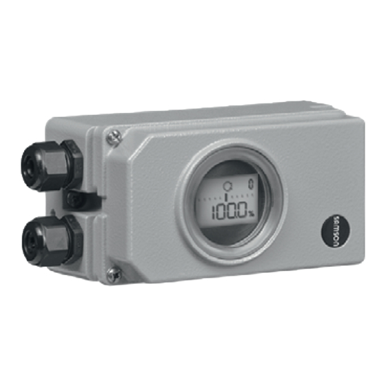
Type 3730-6
electropneumatic positioner
Hide thumbs
Also See for Series 3730:
- Mounting and operating instructions (220 pages) ,
- Operating instructions manual (120 pages) ,
- Mounting and operating instructions (208 pages)

Subscribe to Our Youtube Channel
Related Manuals for Samson Series 3730


Summary of Contents for Samson Series 3730
- Page 1 Series 3730 Type 3730-6 Electropneumatic Positioner with HART communication and pressure sensors ® Old design New design Mounting and Operating Instructions EB 8384-6 EN (1300-1623) Firmware version 1.11 Edition April 2017...
- Page 2 Definition of signal words DANGER! NOTICE Hazardous situations which, if not Property damage message or mal- avoided, will result in death or seri- function ous injury Note: WARNING! Additional information Hazardous situations which, if not avoided, could result in death or seri- Tip: ous injury Recommended action...
-
Page 3: Table Of Contents
Contents Important safety instructions ................7 Article code ....................8 Design and principle of operation ..............9 Safety function (SIL) ..................11 Valve diagnostics ..................11 Communication ...................12 3.4 Configuration using the TROVIS-VIEW software ..........12 Additional equipment ...................12 Technical data .....................14 Attachment to the control valve – Mounting parts and accessories ....20 Direct attachment ..................22 4.1.1 Type 3277-5 Actuator ..................22... - Page 4 Contents 5.1.2 Supply pressure ...................57 5.1.3 Signal pressure (output) ................58 Electrical connections ...................58 5.2.1 Switching amplifier ..................60 5.2.2 Establishing communication ................61 Operating controls and readings ..............63 Serial interface ....................66 HART communication .................66 ® Dynamic HART variables ................66 ® Start-up and settings ...................68 7.1 Determining the fail-safe position ..............68 Adjusting the volume restriction Q ..............69...
- Page 5 Contents 9.1 Retrofitting an inductive limit contact ..............89 Maintenance ....................91 Servicing explosion-protected devices ............91 Firmware update (serial interface) ..............91 Maintenance, calibration and work on equipment ........92 Code list .....................93 Dimensions in mm ..................112 15.1 Fixing levels according to VDI/VDE 3845 (September 2010) ......115 Valve characteristic selection ..............116 Test certificates ..................118 EB 8384-6 EN...
-
Page 6: Eb 8384-6 En
Positioner firmware revisions 1.0x 1.10 A positioner not yet initialized has the NAMUR status “Out of specification” (previously “Failure”. Revised default setting of diagnostic parameters (u EB 8389-1) 1.10 1.11 A positioner not yet initialized has the NAMUR status “Out of specification” (“Failure” in firmware version 1.10 and lower). Default values of the dynamic test adapted to the positioner series. Further production-related revisions. Note: The functions of the EXPERTplus Valve Diagnostics are described in the Operating In- structions EB 8389-1. -
Page 7: Important Safety Instructions
Important safety instructions 1 Important safety instructions For your own safety, follow these instructions concerning the mounting, start-up and opera- tion of the device: − The device is to be mounted, started up or operated only by trained and experienced personnel familiar with the product. According to these mounting and operating instruc- tions, trained personnel is referred to as individuals who are able to judge the work they are assigned to and recognize possible dangers due to their specialized training, their knowledge and experience as well as their knowledge of the applicable standards. − Explosion-protected versions of this device are to be operated only by personnel who has undergone special training or instructions or who is authorized to work on explosion-pro- tected devices in hazardous areas. Refer to section 11. − Any hazards that could be caused in the valve by the process medium, the signal pres- sure or by moving parts are to be prevented by taking appropriate precautions. − If inadmissible motions or forces are produced in the pneumatic actuator as a result of the supply pressure level, it must be restricted using a suitable supply pressure reducing station. To avoid damage to any equipment, the following also applies: −... - Page 8 Article code 2 Article code Positioner Type 3730-6 x x x x x x x 0 x x 0 x 0 0 With HART communication and pressure sensors ® Explosion protection Without 0 0 0 ATEX II 2G Ex ia IIC/IIB T6; II 2D Ex tb IIIC T6 IP66 1 1 0 IECEx Ex ia IIC/IIB T6; Ex d[ia] IIC/IIB T6; Ex tD A21 IP66 T80°C 1 1 1 GOST 1Ex ia IIC T6 Gb; 1Ex tb IIIC T80°C Db IP66 1 1 3...
-
Page 9: Article Code
Article code Positioner Type 3730-6 x x x x x x x 0 x x 0 x 0 0 With HART communication and pressure sensors ® Housing material Aluminum (standard) Stainless steel 1.4581 Special applications Without Device compatible with paint Exhaust air port with ¼-18 NPT thread, back of positioner sealed Attachment according to VDI/VDE 3847 including interface Attachment according to VDI/VDE 3847 prepared for interface EB 8384-6 EN... -
Page 10: Design And Principle Of Operation
(5). types of attachment using the corresponding The positioner is fitted with three binary con- accessories: tacts as standard: A fault alarm output indi- − Direct attachment to SAMSON cates a fault to the control room and two Type 3277 Actuator configurable software limit contacts are used − Attachment to actuators according to IEC to indicate the end positions of the valve. - Page 11 Design and principle of operation Serial Interface Depending on version >3.8 mA & >4.4 mA >12 V 24 V DC Control valve Software limit contacts A1/A2 Travel sensor Fault alarm output A3 PD controller A/D converter 17* Actuation of solenoid valve Microcontroller Electrical insulation i/p converter D/A converter...
-
Page 12: Safety Function (Sil)
Design and principle of operation 3.1 Safety function (SIL) 3.2 Valve diagnostics The safety function is based on the shutdown The EXPERTplus valve diagnostics are inte- of the i/p converter (6). This causes the grated into the positioner. They provide in- pneumatic actuator to be vented and the formation on the control valve and generate valve to move to its fail-safe position. -
Page 13: Communication
TROVIS-VIEW can be downloaded transmitter and issues the travel sensor signal free of charge from our website at as a 4 to 20 mA signal processed by the mi- http:\\www.samson.de > Services > crocontroller. Since this signal is issued inde- Software > TROVIS-VIEW. pendent of the positioner’s input signal, the momentary travel/angle of rotation is con- trolled in real-time. Additionally, the position... - Page 14 Design and principle of operation cated over a signal current of <2.4 mA or − Various diagnostic functions >21.6 mA. Details on EXPERTplus Valve Diagnostics in the Operating Instructions Leakage sensor u EB 8389-1. By upgrading the positioner with a leakage Additionally, the external solenoid valve sensor, it is possible to detect seat leakage function can be selected if a non-floating when the valve is in the closed position. De- contact is configured: tails on EXPERTplus Valve Diagnostics in the − External solenoid valve Operating Instructions u EB 8389-1.
-
Page 15: Technical Data
Design and principle of operation 3.6 Technical data Type 3730-6 Positioner: the technical data for the explosion-protected devices may be restricted by the limits specified in the test certificates. Travel Adjustable Direct attachment to Type 3277 Actuator: 3.6 to 30 mm Attachment according to IEC 60534-6-1: 3.6 to 200 mm Attachment according to VDI/VDE 3847: 3.6 to 200 mm Rotary actuators: 24 to 100° opening angle Travel range Adjustable Adjustable within the initialized travel/angle of rotation; travel can be restricted to 1/5 at the maximum Reference Signal range... - Page 16 Degree of protection IP 66/NEMA 4X Use in safety-instrumented Suitable for use in safety-instrumented systems up to SIL 2 (single device/HFT = 0) systems according to and SIL 3 (redundant configuration/HFT = 1) according to IEC 61511. IEC 61508/SIL • Triggered by the set point, emergency venting depending on positioner ver- sion at ≤3.8 mA or ≤4.4 mA • By the optional solenoid valve, emergency venting at 0 V • By the optional forced venting, emergency venting at <12 V Communication (local) SAMSON SSP interface and serial interface adapter, software requirement (SSP): TROVIS-VIEW with database module 3730-6 Communication (HART HART field communications protocol · Impedance in HART frequency range: Re- ® ® ® ceiving 350 to 450 Ω · Sending approx. 115 Ω Software re- For handheld Device description for Type 3730-6 quirements communicator (HART ®...
- Page 17 Design and principle of operation Type 3730-6 Positioner: the technical data for the explosion-protected devices may be restricted by the limits specified in the test certificates. Conformity · Options for Type 3730-6 Positioner Electronic forced venting· Approval acc. to IEC 61508/SIL Input 24 V DC · Electrical isolation and reverse polarity protection · Static destruction limit 40 V (corresponding to 4.8 mA at U – 5.7 V Power consumption: I = 3.84 kΩ...
- Page 18 Design and principle of operation External position sensor Travel Same as positioner Cable 10 m · Flexible and durable · With M12x1 connector · Flame-retardant acc. to VDE 0472 · Resistant to oils, lubricants and coolants as well as other aggressive media Permissible ambient –40 to +90 °C with a fixed connection between positioner and position sensor temperature The limits in the test certificate additionally apply for explosion-protected versions. Immunity to vibration Up to 10 g in the range of 10 to 2000 Hz Degree of protection IP 67 Binary input · Electrical isolation · Switching behavior configured over software Active switching behavior (default setting) Connection For external switch (floating contact) or relay contact Electric data Open-circuit voltage when contact is open: max. 10 V Pulsed DC current reaching peak value of 100 mA and RMS value of 0.01 mA when contact is closed Contact Closed, ON switching state (default setting) R < 20 Ω...
- Page 19 Design and principle of operation Summary of explosion protection certificates for Type 3730-6 Positioner Type Certification Type of protection/Comments Number PTB 10 ATEX 2007 II 2G Ex ia IIC/IIB T6; EC type II 2D Ex tb IIIC T80°C IP66 Date 2010-08-18 examination certificate Number GYJ12.1109X Ex ia IIC T4~T6 Ga; NEPSI Date 2012-10-08 DIP A21 Ta, T4~T6 Valid until 2017-10-07 Number IECEx PTB 10.0057...
- Page 20 Design and principle of operation Type Certification Type of protection/Comments Number PTB 10 ATEX 2007 With Type 3770-1 Field barrier: II 2G Ex d[ia] IIC/IIB T6 Gb; EC type Date 2010-08-18 II 2D Ex tb IIIC T80°C IP66 examination certificate Number IECEx PTB 10.0057 Ex ia IIC/IIB T6; Ex d[ia] IIC/IIB T6; IECEx Ex tD A21 IP66 T80°C Date 2011-01-10 Number RU C-DE.08.B.00113 Date 2013-11-15 1Ex d[ia Ga]iiC T6 Gb X Valid until 2018-11-14 Number PTB 10 ATEX 2008 X II 3G Ex nA ic IIC T6 Gc; II 3D Ex tc IIIC T80°C Dc IP66 Statement of Date 2010-08-18...
-
Page 21: Attachment To The Control Valve - Mounting Parts And Accessories
4. Connect the electrical power. sion of the actuator springs. 5. Perform the start-up settings. The positioner is equipped with the M lever (pin position 35) as standard. The positioner is suitable for the following types of attachment: − Direct attachment to SAMSON Type 3277 Actuator − Attachment to actuators according to IEC 60534-6 (NAMUR) − Attachment according to VDI/VDE 3847 − Attachment to Type 3510 Micro-flow Valve −... - Page 22 [cm²] [mm] Travel [mm] 25.0 120/175/240/350 35.0 355/700/750 10.0 50.0 Attachment according to IEC 60534-6 (NAMUR) SAMSON valves with Type 3271 Adjustment range at positioner Actuator Other control valves Actuator size Rated travel Min. travel Max. travel Required Assigned pin [cm²] [mm]...
-
Page 23: Direct Attachment
Attachment to the control valve – Mounting parts and accessories 4.1 Direct attachment Make sure that the gasket (14) points to- wards the actuator yoke. 4.1.1 Type 3277-5 Actuator 4. 15 mm travel: Keep the follower pin (2) on the M lever (1) on the back of the po- − Required mounting parts and accesso- sitioner in the pin position 35 (delivered ries: Table 2 on page 53 state). - Page 24 Attachment to the control valve – Mounting parts and accessories EB 8384-6 EN...
-
Page 25: Type 3277 Actuator
Attachment to the control valve – Mounting parts and accessories 4.1.2 Type 3277 Actuator Adjust the lever (1) correspondingly and open the positioner cover to hold the po- − Required mounting parts and accesso- sitioner shaft in position at the cap or ro- ries: Table 2 on page 53 tary pushbutton. The lever (1) must rest −... - Page 26 Attachment to the control valve – Mounting parts and accessories Marking EB 8384-6 EN...
-
Page 27: Attachment According To Iec 60534-6
Attachment to the control valve – Mounting parts and accessories 4.2 Attachment according to aligned with the NAMUR bracket at mid valve travel). IEC 60534-6 3. Mount connecting plate (6) or pressure − Required mounting parts and accesso- gauge bracket (7) with pressure gauges ries: Table 3 on page 54 on the positioner, making sure the two − Observe the travel table on page 22. seals (6.1) are seated properly. - Page 28 Attachment to the control valve – Mounting parts and accessories Attachment to rod-type yoke Rods with 20 to 35 mm diameter Attachment to NAMUR rib Additional bracket for actuators with 2800 cm² and travel ≥ 60 mm Lever XL and L lever 1.1 Nut 1.2 Disk spring Follower pin Follower plate 3.1 Follower plate Connecting plate 6.1 Seals Pressure gauge bracket Pressure gauge mounting kit Stem connector 9.1 Bracket NAMUR bracket Screw Bolt...
-
Page 29: Attachment According To Vdi/Vde 3847
Attachment to the control valve – Mounting parts and accessories 4.3 Attachment according to mounting screw is located in the groove of the actuator stem. VDI/VDE 3847 2. Place the adapter bracket (6) on the po- Type 3730-6-xxxxxxx0xx0600 and sitioner and mount using the screws Type 3730-6-xxxxxxx0xx0700 Positioners (6.1). Make sure that the seals are cor- with air purging of the actuator's spring rectly seated. - Page 30 Attachment to the control valve – Mounting parts and accessories EB 8384-6 EN...
- Page 31 Attachment to the control valve – Mounting parts and accessories 7. Insert the screws (13.1) through the mid- Place positioner on the adapter block dle holes of the adapter block (13). (13) in such a manner that the follower pin (2) rests on the top of the follower 8. Place the connecting plate (12) together clamp (3).
- Page 32 Attachment to the control valve – Mounting parts and accessories Attachment to NAMUR rib (see Fig. 8) on the rod and position the formed plate (15) on the opposite side. Use the nuts − Required mounting parts and accesso- and toothed lock washers to fasten the ries: Table 4 on page 54 formed plate onto the studs.
- Page 33 Attachment to the control valve – Mounting parts and accessories 6. Insert the formed seal (17.1) into the For double-acting actuators and actua- turnboard (17) and mount the turnboard tors with air purging, connect the Y2 to the adapter block (13) using the port of the adapter block to the signal pressure connection of the second actua- screws (17.2). tor chamber or spring chamber of the 7.
- Page 34 Attachment to the control valve – Mounting parts and accessories Lever 1.1 Nut 1.2 Disk spring Follower pin Follower plate 13.1 Screw 3.1 Follower plate Bolt Blanking plug 14.1 Screw Sealing plug Formed plate Adapter bracket Bracket 6.1 Screw Turnboard 6.2 Molded seal 17.1 Molded seal 6.3 Screw 17.2 Screw NAMUR...
-
Page 35: Attachment To Type 3510 Micro-Flow Valve
The positioner is mounted to the rotary actu- 4. Fasten the hex bar (11) onto the outer ator using two pairs of brackets. side of yoke by screwing the M8 screws Prior to attaching the positioner to the (11.1) directly into the holes on the yoke. SAMSON Type 3278 Rotary Actuator, 5. Fasten the bracket (10) to the hex bar us- mount the associated adapter (5) to the free ing the hex screw (10.1), washer, and end of the rotary actuator shaft. tooth lock washer. - Page 36 Attachment to the control valve – Mounting parts and accessories Lever 1.1 Nut 1.2 Disk spring NOTICE Follower pin Only use the connecting plate (6) Follower plate included in the accessories to connect Connecting plate supply and output! 6.1 Seal Never screw threaded parts directly Pressure gauge bracket into housing! Pressure gauge...
-
Page 37: Heavy-Duty Version
Attachment to the control valve – Mounting parts and accessories 2. Place coupling wheel (4) with flat side side of the positioner housing (see section facing the actuator on the follower clamp 4.6). (3). Refer to Fig. 11 to align slot so that it 6. Unscrew the standard follower pin (2) matches the direction of rotation when the from the positioner's M lever (1). - Page 38 Attachment to the control valve – Mounting parts and accessories EB 8384-6 EN...
-
Page 39: Reversing Amplifier For Double-Acting Actuators
(11) underneath, if neces- 5. Unscrew the standard follower pin (2) sary. from the positioner's M lever (1). Attach the follower pin (Ø 5 mm) included in 2. For SAMSON Type 3278 and VETEC the mounting kit to pin position 90°. S160 Rotary Actuators, screw the adapt- 6. Mount connecting plate (6) for required er (5) onto the free end of the shaft or G ¼ connecting thread or pressure... - Page 40 Attachment to the control valve – Mounting parts and accessories EB 8384-6 EN...
-
Page 41: Reversing Amplifier (1079-1118 Or 1079-1119)
Attachment to the control valve – Mounting parts and accessories The following applies to all reversing am- 2. Thread the special nuts (1.3) from the ac- plifiers: cessories of the reversing amplifier into the boreholes of the connecting plate. The signal pressure of the positioner is sup- plied at the output 1 of the reversing amplifi- 3. Insert the gasket (1.2) into the recess of er. - Page 42 Attachment to the control valve – Mounting parts and accessories EB 8384-6 EN...
-
Page 43: Attachment Of External Position Sensor
Attachment to the control valve – Mounting parts and accessories 4.7 Attachment of external Operation and setting are described in sections 7 and 8. position sensor − Since 2009, the back of the posi- tion sensor (20) is fitted with two pins acting as mechanical stops for the lever (1). - Page 44 Attachment to the control valve – Mounting parts and accessories Type 3277 Actuator with 175 to 750 cm²: together with the disk spring (1.2) from the sensor shaft. The signal pressure is routed to the connec- tion at the side of the actuator yoke for the 2. Screw the position sensor (20) onto the version with fail-safe action "actuator stem mounting plate (21).
-
Page 45: Mounting The Position Sensor With Attachment According To Iec 60534-6
Attachment to the control valve – Mounting parts and accessories 4. Place the lever (1) and disk spring (1.2) stalled to allow any condensed water on the sensor shaft. Place the lever in that collects to drain off. mid-position and hold it in place. Screw 4.7.2 Mounting the position on the nut (1.1). -
Page 46: Mounting The Position Sensor To Type 3510 Micro-Flow Valve
Attachment to the control valve – Mounting parts and accessories 2. Screw the position sensor (20) onto the 5. Place the bracket with the sensor at the bracket (21). NAMUR rib in such a manner that the follower pin (2) rests in the slot of the fol- The standard attached M lever with the fol- lower plate (3), then screw the bracket lower pin (2) at position 35 is designed for using its fixing screws onto the valve. -
Page 47: Mounting On Rotary Actuators
Attachment to the control valve – Mounting parts and accessories 4.7.4 Mounting on rotary with the disk spring (1.2) from the sen- sor shaft. actuators 2. Screw the position sensor (20) onto the − Required mounting parts and accesso- bracket (21). ries: Table 7 on page 57 3. Select the S lever (1) from the accessories and screw the follower pin (2) into the Fig. 18 hole for pin position 17. - Page 48 Attachment to the control valve – Mounting parts and accessories 4. Place the lever (1) and disk spring (1.2) on the sensor shaft. Place the lever in mid-position and hold it in place. Screw on the nut (1.1). Follow the instructions describing attachment to the standard positioner in section 4.5. Instead of the positioner, attach the position sensor (20) with its mounting plate (21).
-
Page 49: Mounting The Leakage Sensor
Attachment to the control valve – Mounting parts and accessories 4.8 Mounting the leakage The M8 threaded connection on the NAMUR rib should preferably be used to mount the sensor sensor (Fig. 19). Fig. 19 Tip: Normally, the control valve is delivered with If the positioner was mounted directly positioner and leakage sensor already onto the actuator (integral mounted. attachment), the NAMUR interfaces If the leakage sensor is mounted after the on either side of the valve yoke can valve has been installed or it is mounted on-... -
Page 50: Attaching Positioners With Stainless Steel Housings
Attachment to the control valve – Mounting parts and accessories 4.9 Attaching positioners with Attachment to rotary actuators stainless steel housings All mounting kits from Table 5 can be used except for the heavy-duty version. Connect- Positioners with stainless steel housings re- ing plate in stainless steel. quire mounting parts that are completely 4.10 Air purging function for made of stainless steel or free of aluminum. - Page 51 Attachment to the control valve – Mounting parts and accessories Attachment according to IEC 60534-6 Should other valve accessories be used (NAMUR rib or attachment to rod-type which vent the actuator (e.g. solenoid valve, yokes) and to rotary actuators volume booster, quick exhaust valve), this ex- haust air must also be included in the purg- The positioner requires an additional port for ing function.
-
Page 52: Required Mounting Parts And Accessories
Attachment to the control valve – Mounting parts and accessories 4.11 Required mounting parts and accessories Table 1: Direct attachment to Type 3277-5 Actuator (Fig. 3) Order no. Standard version for actuators 120 cm² or smaller 1400-7452 Mounting parts Version compatible with paint for actuators 120 cm² or smaller 1402-0940 Old switchover plate for Type 3277-5xxxxxx.00 Actuator (old) 1400-6819 New switchover plate for Type 3277-5xxxxxx.01 Actuator (new) 1400-6822 Accessories for New connecting plate for Type 3277-5xxxxxx.01 Actuator (new) , G ... - Page 53 Attachment to the control valve – Mounting parts and accessories Table 2: Direct attachment to Type 3277 Actuator (Fig. 4) Order no. Standard version for actuators 175, 240, 350, 355, 700, 750 cm² 1400-7453 Mounting parts Version compatible with paint for actuators 175, 240, 350, 355, 700, 750 cm² 1402-0941 G / G 1402-0970 ¼ Steel NPT/ NPT 1402-0976 ¼ 175 cm² G / G 1402-0971 ¼ St.
- Page 54 Pressure gauge mounting kit up to max. 6 bar (output/supply) Stainless steel/ 1402-0939 stainless steel M lever is mounted on basic device (included in the scope of delivery) In conjunction with Type 3273 Side-mounted Handwheel with 120 mm rated travel, additionally one bracket (0300-1162) and two countersunk screws (8330-0919) are required. Table 4: Attachment according to VDI/VDE 3847 (Fig. 6 and Fig. 8) Electropneumatic positioners with VDI/VDE 3847 interface Type 3730-6-xxxxxxx0xx0700 Order no. Interface adapter 1402-0257 Mounting kit for attachment to SAMSON Type 3277 Actuator with 175 to 750 cm² 1402-0868 Mounting kit for attachment to SAMSON Type 3271 Actuator or non-SAMSON 1402-0869 actuators ISO 228/1-G¼ 1402-0268 Mounting Aluminum parts ¼-18 NPT 1402-0269 Connecting plate, including connection for air purging of actuator spring chamber ISO 228/1-G¼...
- Page 55 Table 5: Attachment to rotary actuators (Fig. 10 and Fig. 11) Order no. Attachment acc. to VDI/VDE 3845 (September 2010), see section 15.1 for details Actuator surface corresponds to fixing level 1 Size AA1 to AA4, version with CrNiMo steel bracket 1400-7448 Size AA1 to AA4, heavy-duty version 1400-9244 Size AA5, heavy-duty version (e.g. Air Torque 10 000) 1400-9542 Bracket surface corresponds to fixing level 2, heavy-duty version 1400-9526 1400-8815 Mounting Attachment for rotary actuators with max. 180° opening angle, fixing level 2 parts 1400-9837 Attachment to SAMSON Type 3278 with 160/320 cm², CrNiMo steel bracket 1400-7614 Attachment to SAMSON Type 3278 with 160 cm² and to VETEC Type S160, Type R and 1400-9245 Type M, heavy-duty version 1400-5891 Attachment to SAMSON Type 3278 with 320 cm² and to VETEC Type S320, heavy-duty version 1400-9526 Attachment to Camflex II 1400-9120 G 1400-7461 ¼ Connecting plate (6) NPT 1400-7462 ¼...
- Page 56 Nickel-plated brass (6 to 12 mm clamping range) 1890-4875 Nickel-plated brass (10 to 14 mm clamping range) 1922-8395 Stainless steel 1.4305 (8 to 14.5 mm clamping range) 8808-0160 Powder-coated aluminum 0310-2149 Adapter M20 x 1.5 to ½ NPT Stainless steel 1400-7114 Retrofit kit for inductive limit contact 1 x SJ2-SN 1400-7460 DE/EN (delivered state) 1990-0761 Cover plate with list of parameters and operating instructions EN/ES 1990-3100 EN/FR 1990-3142 TROVIS-VIEW 6661 with device module Type 3730-6 Serial interface adapter (SAMSON SSP interface to RS-232 port on a computer) 1400-7700 Isolated USB interface adapter (SAMSON SSP interface to USB port on a computer) 1400-9740 including TROVIS-VIEW CD-ROM EB 8384-6 EN...
- Page 57 Size AA1 to AA4 with follower clamp and coupling wheel, version with CrNiMo steel bracket. See Fig. 18. 1400-7473 Size AA1 to AA4, heavy-duty version 1400-9384 Size AA5, heavy-duty version (e.g. Air Torque 10 000) 1400-9992 Attachment to ro- tary actuators Bracket surface corresponds to fixing level 2, heavy-duty 1400-9974 version SAMSON Type 3278 with 160 cm² and VETEC Type S160 and Type R, heavy- 1400-9385 duty version 1400-5891 SAMSON Type 3278 with 320 cm² and VETEC Type S320, heavy-duty version 1400-9974 G 1400-7461 ¼ Connecting plate (6) NPT 1400-7462 ¼...
-
Page 58: Connections
Connections 5 Connections a bore with ¼ NPT or G ¼ thread. Custom- ary fittings for metal or copper tubing or WARNING! plastic hoses can be used. Risk of injury due to the actuator stem extending or retracting! NOTICE Do not touch or block the actuator Risk of malfunction due to failure to stem! comply with required air quality. Only use supply air that is dry and free of oil and dust. -
Page 59: Signal Pressure (Output)
Connections 5.1.3 Signal pressure (output) The bench range is written on the nameplate either as the spring range or signal pressure The signal pressure at the output (38) of the range depending on the actuator. The direc- positioner can be restricted to 1.4 bar, tion of action is marked FA or FE, or by a 2.4 bar or 3.7 bar in Code 16. symbol. The limitation is not activated [7.0 bar] by Note: default. PLOW is indicated under Code 0 if the supply pressure p is lower than 5.2 Electrical connections the upper spring range value deter-... - Page 60 Connections Selecting cables and wires ambient temperatures below –20 °C with metal cable entries. Observe clause 12 of EN 60079-14 (VDE 0165, Part 1) for installation of the in- Equipment for use in zone 2/zone 22 trinsically safe circuits. In equipment operated according to type of Clause 12.2.2.7 applies when running multi- protection Ex nA II (non-sparking equipment) core cables and wires with more than one according to EN 60079-15: 2003, circuits intrinsically safe circuit. may be connected, interrupted or switched The radial thickness of the insulation of a while energized only during installation, conductor for common insulating materials maintenance or repair.
-
Page 61: Switching Amplifier
Connections equipment with energy-limited circuits in Depending on the version, the positioner is type of protection Ex nL IIC. equipped with inductive limit contacts and/ or a solenoid valve. Cable entry The position transmitter is operated on a Cable entry with M20 x 1.5 cable gland. two-wire circuit. The usual supply voltage is See section on Accessories for clamping 24 V DC. Taking the resistance of the supply range. -
Page 62: Establishing Communication
Connections Observe the relevant regulations for installa- If the load impedance of the controller or tion in hazardous areas. control station is too low, an isolation ampli- fier must be connected between controller 5.2.2 Establishing communica- and positioner (interfacing as for positioner connected in hazardous areas). See Fig. 21. tion If the positioner is used in hazardous areas, Communication between PC and positioner an explosion-protected isolation amplifier using an FSK modem or handheld communi-... - Page 63 Connections Standard bus (multidrop): In the standard bus (multidrop) mode, the positioner follows the analog current signal (reference variable) in the same manner as Controller/control station for point-to-point communication. This oper- ating mode is, for example, suitable for split- range operation of positioners (series con- Fig. 22: Adapting the output signal nection). The bus address/polling address has to be within a range of 1 to 15. Note: Communication errors may occur when the process controller/control station output is not HART-compati- ble.
-
Page 64: Operating Controls And Readings
Operating controls and readings 6 Operating controls and read- ble-acting rotary actuators (connections ac- cording to section 4.6). ings Volume restriction Q Rotary pushbutton The volume restriction serves to adapt the air The rotary pushbutton is located underneath output capacity to the size of the actuator. the front protective cover. The positioner is Depending on the air passage at the actua- operated on site using the rotary pushbutton: tor, two fixed settings are available. - Page 65 Operating controls and readings Readings been exceeded. Lever and pin position must be checked. Icons assigned to certain codes, parameters and functions are indicated on the display. Status messages Operating modes: Failure − Maintenance demanded/Mainte- − Manual mode (see section 8.2.1) − nance required The positioner follows the manual set blinks: Out of specification − point (Code 1) instead of the mA signal.
- Page 66 Operating controls and readings Maintenance demanded/ Maintenance required Fail-safe position active Configuration enabled Blinks: Out of specification Limit contact alarm 2 Limit contact alarm 1 Units Designation Position Bar graph for set point Parameters deviation or lever position Closed-loop operation Code Manual mode Malfunction/fault AUTO Automatic blinking Emergency mode (see error code 62) Clockwise blinking Positioner not initialized...
-
Page 67: Serial Interface
Operating controls and readings 6.1 Serial interface Locking HART communication ® The write access for HART communication ® The positioner must be supplied with at least can be disabled over Code 47. This function 3.8 mA. can only be enabled or disabled locally at The positioner can be connected directly to the positioner. the PC over the local serial interface and the Write access is enabled by default. serial interface adapter. The operator soft- ware is TROVIS-VIEW (version 4) with in- Locking on-site operation stalled device module 3730-6. - Page 68 Operating controls and readings Table 8: Dynamic HART variables assignment ® Variable Meaning Unit Set point Set point Direction of action set point Direction of action set point Set point after transit time Set point after transit time specification specification Valve position Actual value (process variable) Set point deviation e Set point deviation e Absolute total valve travel Absolute total valve travel...
-
Page 69: Start-Up And Settings
Start-up and settings 7 Start-up and settings Note: The positioner performs a test in the NOTICE start-up phase while following its au- Malfunction due to incorrect se- tomation task at the same time. quence of mounting, installation and During the start-up phase, operation start-up. -
Page 70: Adjusting The Volume Restriction Q
Start-up and settings Initialize an initialized positioner Note: again after the position of the volume The switch position is prompted prior restriction has been changed. to an initialization. After an initial- ization has been completed, chang- ing the switch position does not have 7.3 Adapting the display direc- any effect on the operation of the po- tion... -
Page 71: Checking The Operating Range Of The Positioner
Start-up and settings Select manual mode: Note: If no settings are entered within 120 seconds, the enabled configuration Operating mode function becomes invalid. Default MAN Turn Code 0 Enable configuration Default: No Press , Code 0 blinks. Turn MAN Press . -
Page 72: Initialization
Start-up and settings The permissible range has been exceed- Malfunction due to changed mount- ed when the displayed angle is more ing or installation circumstances! than 30° and the outer right or left bar Reset the positioner to its default set- element blinks. The positioner goes to the tings and re-initialize it after the posi- fail-safe position (SAFE). - Page 73 Start-up and settings − Substitute calibration (SUb) This mode allows a positioner to be re- Bar graph display indicating placed while the plant is running, with the the progress of the initializa- tion least amount of disruption to the plant (see section 7.6.5). Note: Initialization successfully com- For normal operation, simply start pleted.
-
Page 74: Max - Initialization Based On Maximum Range
Start-up and settings Reference variable w Fail-safe Direction of Valve position action Default: No CLOSED OPEN at AIR TO OPEN 0 % 100 % AIR TO CLOSE 100 % 0 % g Code 3, display: No Turn The tight-closing function has been activated. Press , Code 3 blinks. Set Code 15 (final position w>) to 99 % for Turn ... -
Page 75: Nom - Initialization Based On Nominal Range
Start-up and settings After initialization, the maximum travel/an- Enter the pin position and nominal range: gle of rotation (Code 5) which was detected during initialization is indicated. Pin position Default: No 7.6.2 NOM – Initialization based on nominal range The calibrated sensor allows the exact valve Nominal range travel to be measured very accurately. (locked when Code 4 = No) During initialization, the positioner checks whether the control valve can move through the indicated nominal range (travel or angle) Turn ... -
Page 76: Man - Initialization Based On A Manually Selected Open Position
Start-up and settings YES Turn Note: If the nominal range determined Press , display: during initialization is smaller than Enter the pin position: the range entered in Code 5, initial- ization is canceled and an error mes- sage (Code 52) is generated. Pin position Default: No Î... -
Page 77: Man2 - Initialization Based On Manually Selected End Positions
Start-up and settings Enable configuration: Press Turn Code 1 Note: If no settings are entered within 120 Press , Code 1 blinks. seconds, the enabled configuration Turn clockwise in small steps until the re- function becomes invalid. quired valve position is reached. The valve must be moved with a monotonically in- creasing signal pressure. -
Page 78: Sub - Substitute Calibration
Start-up and settings 7.6.5 SUB – Substitute calibra- tion POS1 (end position 1) A complete initialization procedure takes several minutes and requires the valve to move through its entire travel range several times. This initialization mode, however, is POS2 (end position 2) an emergency mode, in which the control parameters are estimated and not deter- mined by an initialization procedure. As a Turn... - Page 79 Start-up and settings Select the initialization mode: Enable configuration Default: No Init mode Default MAX g Code 3, display: No Turn Press , Code 3 blinks. Turn Code 6 Turn YES Press SUB Press , display: Turn Press to confirm the SUB as the initializa- Enter the pin position and nominal range: tion mode.
- Page 80 Start-up and settings Change pressure limit and control parame- Enter closing direction and blocking position: ters: Closing direction (direction of rotation causing the valve to Note: move to the CLOSED position Do not change the pressure limit (view onto positioner display) (Code 16).
-
Page 81: Tuning The Kp Input Filter
Start-up and settings Tuning the input filter Note: − Since initialization has not been completed, the error code 76 (no Tuning the input filter emergency mode) and possibly al- Default MAX so error code 57 (control loop) may appear on the display. These alarms do not influence the posi- Turn ... -
Page 82: Reset To Default Settings
Start-up and settings Enable configuration: Enable configuration: g Code 3, display: No g Code 3, display: No Turn Turn , Code 3 blinks. , Code 3 blinks. Press Press Turn YES Turn YES Press , display: Press , display: Perform zero calibration: Reset start-up parameters: Init mode Reset... - Page 83 Start-up and settings Table 9: Reset functions Reset Code 36 DIAG Initialization Fail-safe action Air supply failure Power supply failure of positioner Power supply failure of external solenoid valve Emergency mode Operating hours counter Device in operation Device switched on since initialization Device in operation since initialization Logging Code...
- Page 84 Start-up and settings Reset Code 36 DIAG Tolerance band Select characteristic Enter transit time OPEN Enter transit time CLOSED Total valve travel limit Alarm mode Limit A1 Limit A2 Error message in case of condensed state 'Function check' Error message in case of 'Maintenance required' and 'Out of specification' condensed states Inductive limit contact Bus address 48 - Diagnostics (u EB 8389-1 EN) 49 - EB 8384-6 EN...
-
Page 85: Operation
Operation 8 Operation Turn to select the required code. Press to activate the selected code. The WARNING! code number starts to blink. Risk of injury due to the actuator Turn to select the setting. stem extending or retracting. Press to confirm the selected setting. Do not touch or block the actuator stem. -
Page 86: Fail-Safe Position (Safe)
Operation Note: The positioner automatically returns Automatic mode to Code 0 if no settings are made within 120 seconds, but remains in the manual mode. Switching to manual mode (MAN) Switch to automatic mode Turn Code 0 Press , Code 0 blinks. Turn ... -
Page 87: Fault/Malfunction
Operation Exit the fail-safe position − Maintenance required The positioner still performs its control Turn Code 0 task (with restrictions). A maintenance , Code 0 blinks. Press demand or above average wear has Turn and select the required operating been determined. The wear tolerance will mode (AUTO or MAN). soon be exhausted or is reducing at a Press faster rate than expected. Maintenance is The positioner switches to the operating necessary in the medium term. -
Page 88: Confirming Error Messages
Operation The message with the highest priority deter- Turn YES mines the condensed state in the positioner. Press , display: If fault alarms exist, the possible source of Confirming error message: error is displayed in Code 49 onwards. In Turn Select the error code that you this case, ERR appears on the display. want to confirm. -
Page 89: Adjusting The Limit Contact
Adjusting the limit contact 9 Adjusting the limit contact Note: The inductive limit contact replaces The positioner version with an inductive limit the software limit contact A1 with ter- contact has an adjustable tag (1) mounted minal assignment +41/–42. Each on the axis of rotation, which operates the switching position can optionally be proximity switch (3). -
Page 90: Retrofitting An Inductive Limit Contact
Adjusting the limit contact Adjusting the switching point: You can measure the switching voltage as an indicator. Note: Contact function: During adjustment or testing, the switching point must always be ap- − Tag leaving the field > Proximity switch proached from mid-position (50 %). assumes low resistance −... - Page 91 Adjusting the limit contact imity switch (7) on the cover with a dot of glue. 4. Remove the jumper (8801-2267) at the socket X7 of the top board and insert the cable connector (11). 5. Guide the cable in such a manner that the plastic cover can be placed back onto the positioner. Insert the fixing screws (2) and screw tight. Attach the clamping plate (8) onto the proximity switch. 6. Attach the rotary switch (5). Make sure the flattened side of the positioner shaft is turned so that the rotary switch (5) can be attached with the metal tag next to the proximity switch.
-
Page 92: Maintenance
12 Firmware update (serial in- stream supply air pressure reducing stations terface) must be observed. Firmware updates on positioners currently in operation can be performed as follows: 11 Servicing explosion-protected When updates are performed by a service employee appointed by SAMSON, the up- devices date is confirmed on the device by the test If a part of the device on which the explosion mark assigned by SAMSON’s Quality Assur- protection is based needs to be serviced, the ance. device must not be put back into operation... -
Page 93: Maintenance, Calibration And Work On Equipment
Maintenance, calibration and work on equipment Updates on site: Updates on site are only permitted after the plant operator presented a signed hot work permit. After updating has been completed, add the current firmware to the nameplate; this can be done using labels. 13 Maintenance, calibration and work on equipment Interconnection with intrinsically safe cir- cuits to check or calibrate the equipment in- side or outside hazardous areas is to be performed only with intrinsically safe cur- rent/voltage calibrators and measuring in-... -
Page 94: Code List
Code list 14 Code list Code Parameter – Readings/ Description values [default setting] Note: Codes with marked with an asterisk (*) must be enabled with Code 3 prior to configuration. Operating mode Switchover from automatic to manual mode is bumpless. [MAN] Manual mode Automatic mode only possible if positioner has been initialized. AUTO Automatic mode SAFE Fail-safe position Display: Code 0, see section 6 Cancel Manual set point (manual w) Adjust the manual reference variable with the rotary pushbutton. - Page 95 Code list Code Parameter – Readings/ Description values [default setting] Pin position Pin position Standard Adjustment range Code 4 Code 5 Code 5 (continued) 3.6 to 17.7 If you select a pin position in 5.0 to 25.0 Code 4 that is too small, the positioner switches to SAFE 15.0 7.0 to 35.4 mode for reasons of safety.
- Page 96 Code list Code Parameter – Readings/ Description values [default setting] Initialization mode Fine tuning of the input filter · The valve moves through its (init mode) entire valve range. (continued) Zero calibration · The zero point is recalibrated. NOTICE Valve will temporarily be moved from its operat- ing point to CLOSED position. Direction of action of the set point in relation to the valve position Direction of action (w/x) Increasing/increasing: a globe valve opens as the set ää:...
- Page 97 Code list Code Parameter – Readings/ Description values [default setting] 10* Lower travel/angle limit Lower limitation of the travel/angle of rotation to the entered val- (lower x-limit) 0.0 to 49.9 % of the operat- The characteristic is not adapted. ing range, [No], ESC 11* Upper travel/angle limit Upper limitation of the travel/angle of rotation to the entered val- (upper x-limit) 50.0 to 120.0 %, [100 %] of The characteristic is not adapted.
- Page 98 Code list Code Parameter – Readings/ Description values [default setting] 14* CLOSED end position (end Limit of the set point w position w <) Actuators with fail-safe action ATO are completely vented and 0.0 to 49.9 %, [1.0 %] of the actuators with fail-safe action ATC are completely filled with air span adjusted in when the set point falls below the adjusted limit. Code 12/13, No, ESC This action always lead to the tight-closing of the valve. Codes 14/15 have priority over Codes 8/9/10/11. Codes 21/22 have priority over Codes 14/15. 15* OPEN end position (end po- Limit of the set point w sition w >) Actuators with fail-safe action ATO are completely filled with air...
- Page 99 Note: The lag time can only be set using the operator software. 20* Select characteristic Select characteristic. See section 16. Linear [0] to 9, ESC Equal percentage Reverse equal percentage SAMSON butterfly valve, linear SAMSON butterfly valve, equal percentage VETEC rotary plug valve, linear VETEC rotary plug valve, equal percentage Segmented ball valve, linear Segmented ball valve, equal percentage User-defined (defined over operator software) 21* Transit time OPEN...
- Page 100 Code list Code Parameter – Readings/ Description values [default setting] 23* Absolute total valve travel Totaled full valve travel cycle [0] to 99 · 10 , YES, ESC Can be reset to 0 in Code 36 – STD and Code 36 – DS. Note: The total valve travel is saved in a non-volatile memory after Exponential reading from 9999 travel cycles onwards every 24 full valve travel cycle. 24* Total valve travel limit Limit of total valve travel limit 1000 to 99 · 10...
- Page 101 Code list Code Parameter – Readings/ Description values [default setting] 26* Limit A1 (alarm limit 1) The valve position limit relating to the operating range. 0.0 to 100.0 [2.0] % of the Alarm A1 responds when the value falls below the limit. operating range, No, ESC The setting has no effect when an inductive limit con- tact is installed. 27* Limit A2 (alarm limit 2) The valve position limit relating to the operating range.
- Page 102 Code list Code Parameter – Readings/ Description values [default setting] 31* Position transmitter test Testing the position transmitter. Values can be entered in relation to the operating range. –10.0 to 110.0 % of the op- erating range · ESC, [default The momentary valve position is used in initialized positioners lo- value is last indicated value cally as the start value (bumpless changeover to the test mode). On of the position transmitter] testing over software, the entered simulation value is issued as the position feedback signal for 30 seconds.
- Page 103 Code list Code Parameter – Readings/ Description values [default setting] 36* Reset DAG: Reset diagnostics assessment − Parameter settings, reference values and logs remain (continued) unchanged. − The positioner does not need to be re-initialized. Resets positioner to default settings. − Resets parameters to their default settings. − Resets diagnostics assessment. −...
- Page 104 Code list Code Parameter – Readings/ Description values [default setting] 44 y info Control signal y in % in relation to the travel range determined during initialization Read only MAX: The positioner builds up its maximum output pressure, see description in Code 14 and 15. The positioner vents completely, see description in Code 14 and 15. – – –: The positioner is not initialized. 45 Internal solenoid valve/ Indicates whether a solenoid valve/forced venting is installed or forced venting not.
- Page 105 Code list Note: The error codes listed in following appear in the display corresponding to their status classification set over the condensed state (Maintenance required/Maintenance de- manded: , Out of specification: blinking, Failure: ). If “No message” is as- signed to the error code as the status classification, the error is not included in the condensed state.
- Page 106 Code list Error codes – Condensed state message active, when prompted, ERR appears. Recommended action When fault alarms exist, they are displayed here. 52 Attachment • The nominal range could not be achieved during initialization with NOM initialization mode (the maximum travel/angle reached is indicated on the display). • Wrong lever mounted. • Supply pressure too low; valve cannot be moved to desired position. Status classification [Maintenance required] Recommended • Check attachment and supply pressure. action •...
- Page 107 Code list Error codes – Condensed state message active, when prompted, ERR appears. Recommended action When fault alarms exist, they are displayed here. 56 Pin/switch Pin position not entered for nominal range (NOM) or substitute (SUB) ini- position tialization. ATO/ATC switch defective. Status classification [Maintenance required] Recommended Enter pin position and nominal range. action Re-initialize positioner. Return positioner to SAMSON for repair. EB 8384-6 EN...
- Page 108 • Valve trim, particularly with soft seat, is worn. Status classification [Maintenance required] Recommended • Check valve and positioner attachment. action • Calibrate zero. We recommend to re-initialize the positioner if zero deviates by more than 5 59 Inconsistent data The error is detected by automatic monitoring and corrected automatically. memory Status classification Failure (cannot be classified) 60 Internal device er- The positioner goes to the fail-safe position (SAFE). Additional indication at the fault alarm contact! Status classification Failure (cannot be classified) Recommended Return positioner to SAMSON for repair. action EB 8384-6 EN...
- Page 109 Note on the closed-loop operation: If the measuring system has failed, the positioner is still in a reliable state. The positioner switches to emergency mode where the position cannot be accurately controlled anymore. However, the positioner continues operation according to its set point so that the process remains in a safe state. Status classification [Maintenance demanded] Recommended Return positioner to SAMSON for repair. action 63 SIL shutdown/w Emergency shutdown of the i/p block is implemented by 3.8 mA or too low 4.4 mA (depending on the positioner version)´. The set point w is lower than 3.7 mA. This state is indicated on the posi- tioner display by LOW blinking.
- Page 110 Code list Error codes – Condensed state message active, when prompted, Err appears. Recommended action When fault alarms exist, they are displayed here. 64 i/p converter (y) Current circuit of i/p converter interrupted. Status classification Failure (cannot be classified) Recommended Return positioner to SAMSON for repair. action EB 8384-6 EN...
- Page 111 SAMSON AG for repair. Unassigned Check calculation Hardware controller monitored by test calculation. Additional indication at the fault alarm contact! Status classification [Failure] Recommended action Confirm error. If this is not possible, return positioner to SAMSON AG for repair. Data error Error codes – Recommended Condensed state message active, when prompted, Err appears. action When fault alarms exist, they are displayed here. 68 to Unassigned No emergency mode The travel measuring system of the positioner has a self-monitoring func- tion (see Code 62).
- Page 112 Status classification [No message] Recommended action Read out test status (only in the operator software) On/off valve The transit time and breakaway time or the final travel/angle value of the on/off valve has changed. Status classification [No message] Recommended action Check valve and actuator. SIL test SIL operator test failed Status classification Failure (cannot be classified) Recommended action Return positioner to SAMSON for repair. EB 8384-6 EN...
-
Page 113: Dimensions In Mm
Dimensions in mm 15 Dimensions in mm Attachment according to IEC 60534-6 Pressure gauge or connecting plate External bracket position sensor Lever (see Fig. 31) Direct attachment M20 x 1.5 Output (38) Supply (9) Fig. 28: NAMUR and direct attachment EB 8384-6 EN... - Page 114 Dimensions in mm Attachment according to VDI/VDE 3847 to Type 3277 Lever (see Fig. 31) Attachment according to VDI/VDE 3847 to a NAMUR Fig. 29: Attachment according to VDI/VDE 3847 EB 8384-6 EN...
- Page 115 Dimensions in mm Heavy-duty version Output Y Output Y Supply (9) Reversing Output Y Output Y amplifier (optional)* Ø 101 Light version Output A1 Supply (9) Reversing Output A2 amplifier (optional)* Connecting plate G ¼ or ¼ NPT * Reversing amplifier Type 3710 (see drawing of heavy-duty version for − dimensions) 1079-1118/1079-1119, no longer available − (see drawing of light version for dimensions) Fig. 30: Attachment to rotary actuators acc.
-
Page 116: Fixing Levels According To Vdi/Vde 3845 (September 2010)
Dimensions in mm Lever 10...17 17 mm 25 mm 33 mm 25 mm 50 mm 66 mm 70 mm 100 mm 116 mm 100 mm 200 mm 216 mm Fig. 31: Lever 15.1 Fixing levels according to VDI/VDE 3845 (September 2010) Fixing level 2 (bracket surface) Fixing level 1 (actuator surface) Actuator Dimensions in mm Size Ød 5.5 for M5 5.5 for M5 5.5 for M5 ØD... -
Page 117: Valve Characteristic Selection
Valve characteristic selection 16 Valve characteristic selection The characteristics that can be selected in Code 20 are shown in following in graph form. Note: A characteristic can only be defined (user-defined characteristic) using a worksta- tion/operator software (e.g. TROVIS-VIEW). Linear (select characteristic: 0) Travel/ angle of rotation [%] Reference variable [%] Equal percentage (select characteristic: 1) Reverse equal percentage (select characteristic: Travel/ angle of rotation [%] Travel/ angle of rotation [%]... - Page 118 SAMSON butterfly valve linear (select charac- SAMSON butterfly valve equal percentage teristic: 3) (select characteristic: 4) Travel/ angle of rotation [%] Travel/ angle of rotation [%] Reference variable [%] Reference variable [%] VETEC rotary plug valve linear (select char- VETEC rotary plug valve equal percentage (se-...
-
Page 119: Test Certificates
EB 8384-6 EN... - Page 120 EB 8384-6 EN...
- Page 121 EB 8384-6 EN...
- Page 122 EB 8384-6 EN...
- Page 123 EB 8384-6 EN...
- Page 124 EB 8384-6 EN...
- Page 125 EB 8384-6 EN...
- Page 126 EB 8384-6 EN...
- Page 127 EB 8384-6 EN...
- Page 128 EB 8384-6 EN...
- Page 129 EB 8384-6 EN...
- Page 130 EB 8384-6 EN...
- Page 131 EB 8384-6 EN...
- Page 132 SAMSON AG · MESS- UND REGELTECHNIK Weismüllerstraße 3 · 60314 Frankfurt am Main, Germany Phone: +49 69 4009-0 · Fax: +49 69 4009-1507 EB 8384-6 EN samson@samson.de · www.samson.de...
Need help?
Do you have a question about the Series 3730 and is the answer not in the manual?
Questions and answers