Samson 3730 Series Mounting And Operating Instructions
Electropneumatic positioner with hart communication
Hide thumbs
Also See for 3730 Series:
- Mounting and operating instructions (220 pages) ,
- Operating instructions manual (120 pages) ,
- Mounting and operating instructions (216 pages)

Related Manuals for Samson 3730 Series


Summary of Contents for Samson 3730 Series
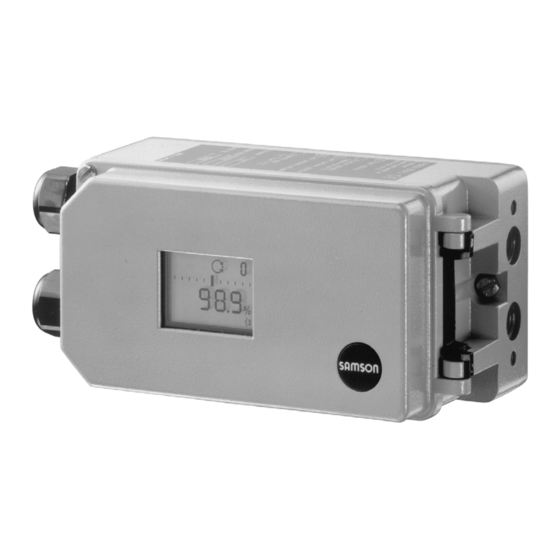
- Page 1 Series 3730 Electropneumatic Positioner Type 3730-3 ® With HART communication Fig. 1 · Type 3730-3 Mounting and Operating Instructions EB 8384-3 EN Firmware version 1.4x Edition August 2007...
-
Page 2: Table Of Contents
Contents Contents Page Design and principle of operation ....8 Communication ......9 Additional equipment . - Page 3 Contents Limiting the signal pressure ..... . 50 Checking the operating range of the positioner ... . . 50 Initialization .
- Page 4 Safety instructions General safety instructions The positioner may only be assembled, started up or operated by trained and experienced personnel familiar with the product. According to these mounting and operating instructions, trained personnel is referred to as individuals who are able to judge the work they are assigned to and recognize possible dangers due to their specialized training, their knowledge and experience as well as their knowledge of the relevant standards.
- Page 5 Versions Type 3730-3 X X X X X 0 0 X 0 X 0 0 X 0 X X Article code Explosion protection Without II 2 G EEx ia IIC T6/II 2 D IP 65 T 80 °C acc. to ATEX CSA/FM intrinsically safe/non incendive II 3 G EEx na II T6 / II 3 D IP 65 T 80 °C acc.
- Page 6 Firmware modification Modifications of positioner firmware in comparison to previous versions Previous 1.00 1.10 The HART protocol as per HART specification Revision 5 is supported by de- fault setting. The setting can be changed to HART Revision 6 over TROVIS-VIEW. HART tools as well as AMS or handheld communicators are currently not supported by the Revision 6 version.
- Page 7 Firmware modification The fault alarm contact is triggered by the condensed status of the positioner. It is always active with “Maintenance alarm” condensed status. If Code 32 is set to Yes : Also active with “Function check” condensed status If Code 33 is set to Yes : Also active with “Maintenance required/Mainte- nance demanded”...
-
Page 8: Design And Principle Of Operation
The positioner is equipped with an interface The positioner basically consists of a travel to allow the SAMSON TROVIS-VIEW Con- sensor system that functions proportional to figuration and Operator Interface software the resistance, an analog i/p module with... -
Page 9: Communication
Design and principle of operation Communication Additional equipment The positioner is equipped with an interface As an option, the device can be additionally for HART ® protocol (Highway Addressable equipped with a solenoid valve for forced Remote Transducer) for communication pur- venting, an analog position transmitter, an poses. - Page 10 Design and principle of operation Positioner with position transmitter The position transmitter (13) is a two-wire transmitter and issues the travel sensor sig- nal as a 4 to 20 mA signal processed by the microcontroller. Since this signal is issued independent of the positioner’s input signal (min.
-
Page 11: Technical Data
Design and principle of operation Technical data Type 3730-3 Positioner Direct attachment to Type 3277: 3.6 to 30 mm Travel, adjustable Attachment acc. to IEC 60534-6: 3.6 to 200 mm Rotary actuators: 24° to 100° Adjustable within the initialized travel/angle of rotation; Travel range travel can be restricted to at the maximum... - Page 12 FM/CSA intrinsically safe Class I, II, III, Division 1, Group A, B, C, D, E, F, G, T6 FM/CSA non incendive Class I, Division 2, Group A, B, C, D, T6 Communication (local) SAMSON SSP interface and serial interface adapter Software requirements TROVIS-VIEW with database module 3730-3 HART ®...
- Page 13 Design and principle of operation Options for Type 3730-3 Positioner Solenoid valve · Approval acc. to IEC 61508/SIL 24 V DC reverse polarity protection, static destruction limit 40 V; − U 5.6 V Input Current consumption I = (corresponding to 4.5 mA at 24 V) Ω...
-
Page 14: Attachment To The Control Valve - Mounting Parts And Accessories
– Mounting parts and accessories The positioner can be attached either di- rectly to a SAMSON Type 3277 Actuator or according to IEC 60534-6 (NAMUR) to con- trol valves with cast yokes or rod-type yokes as well as to rotary actuators according to Fig. - Page 15 3277-5 25.0 3277 120/240/350 35.4 Actuators 10.0 50.0 Travel table for attachment according to IEC 60534-6 (NAMUR) SAMSON valves Other valves/actuators Required Assigned lever pin position cm² Rated travel mm Min. Travel Max. 60 and 120 with 17.7...
- Page 16 Attachment to the control valve – Mounting parts and accessories Table 1 Direct attachment to Type 3277-5 Actuator, see Fig. 4 Mounting parts For actuators with 120 cm² effective diaphragm area 1400-7452 Switchover plate (old) for Actuator Type 3277-5xxxxxx.00 (old) 1400-6819 Switchover plate new for Actuator Type 3277-5xxxxxx.01 (new) 1400-6822...
- Page 17 VDI/VDE 3845 for all sizes of fixing level 2, heavy-duty version 1400-9244 parts Mounting parts for rotary actuators VDI/VDE 3845 (level 1), heavy-duty version 1400-9526 SAMSON Type 3278 160 cm² / VETEC Type S160 and Type R, heavy-duty version 1400-9245 AIR TORQUE 10 000, heavy-duty version 1400-9542 Connecting plate G ¼: 1400-7461...
-
Page 18: Direct Attachment
Attachment to the control valve – Mounting parts and accessories Direct attachment left) pointing towards the signal pressure connection. Make sure that the bonded 2.1.1 Type 3277-5 Actuator gasket (14) points towards the actuator yoke. Refer to Table 1 on page 16 for the required 5. - Page 19 Attachment to the control valve – Mounting parts and accessories Lever Symbols 1.1 Nut Switchover plate (9) 1.2 Disk spring Actuator stem Follower pin extends Follower clamp Screw plug Attachment left Attachment right Stopper Connecting plate Actuator stem 6.1 Seal rings retracts Pressure gauge bracket Press.
-
Page 20: Type 3277 Actuator
Attachment to the control valve – Mounting parts and accessories 2.1.2 Type 3277 Actuator rests on the top of the follower clamp (3). Adjust the lever (1) correspondingly Refer to Table 2 on page 16 or the required and open the positioner cover to hold mounting parts as well as the accessories the positioner shaft in position at the cap with their order numbers. - Page 21 Attachment to the control valve – Mounting parts and accessories Lever 12.1 Screw 1.1 Nut 12.2 Stopper or connection for external piping 1.2 Disk spring Switch plate Follower pin Gasket Follower clamp 10 14 Formed seal 10 Cover plate Gasket 11 Cover 12 Connection block Lever M...
-
Page 22: Attachment According To Iec 60534-6
Attachment to the control valve – Mounting parts and accessories Attachment according to (8) on the positioner, making sure both seal rings (6.1) are seated properly. IEC 60534-6 4. Select required lever size (1) M, L or XL The positioner is attached to the control and pin position according to the actua- valve with a NAMUR bracket (10). - Page 23 Attachment to the control valve – Mounting parts and accessories Attachment to rod-type yoke Rods with 20 to 35 mm Ø Attachment to NAMUR rib Additional bracket for actuators with 2800 cm and travel ≥ 60 mm Lever XL and L Lever 14.1 Disk spring...
-
Page 24: Attachment To Type 3510 Micro-Flow Valve
Attachment to the control valve – Mounting parts and accessories Attachment to Type 3510 Micro-flow Valve The positioner is attached to the valve yoke using a bracket. Refer to Table 3 on page 16 for the required mounting parts as well as the accessories with their order numbers. - Page 25 Attachment to the control valve – Mounting parts and accessories Lever Disk spring Follower pin Clamp Connecting plate Seal rings Pressure gauge bracket Pressure gauge mounting kit Bracket Screw Note! Always use the connecting plate (6) included in the accessories to connect supply and output.
-
Page 26: Attachment To Rotary Actuators
90°. Prior to the attachment of the positioner to 7. Place positioner on top pair of brackets the SAMSON Type 3278 Rotary Actuator, (10) and screw tight. Considering the mount the associated adapter (5) to the free actuator's direction of rotation, adjust le- end of the rotary actuator shaft. - Page 27 Attachment to the control valve – Mounting parts and accessories (7, 8) 10.1 Note! Always use the connecting plate (6) included in the accessories to connect Control valve opens counterclockwise supply and output. Never screw threaded Slot parts directly into the housing.
-
Page 28: Reversing Amplifier For Double-Acting Actuators
Attachment to the control valve – Mounting parts and accessories Reversing amplifier for Note! double-acting actuators The sealing plug (1.5) in the Type 3730 Positioner should not be unscrewed out of For the use with double-acting actuators, the the reversing amplifier. positioner must be fitted with a reversing The rubber seal (1.4) is not required and amplifier. - Page 29 Attachment to the control valve – Mounting parts and accessories From the positioner Output 38 Supply 9 Control signals to the actuator Reversing amplifer Connecting plate 1.1 Special screws 6.1 O-rings 1.2 Gasket 6.2 Screws 1.3 Special nuts 1.4 Rubber seal 1.5 Sealing plug 1.6 Filter Fig.
-
Page 30: Attaching An External Position Sensor
Attachment to the control valve – Mounting parts and accessories Attaching an external position sensor Refer to Table 6 on page 35 for a list of the mounting parts as well as the accessories re- quired for mounting the position sensor. Accessories for the pneumatic connection to the positioner housing can be found in Ta- ble 7. - Page 31 Attachment to the control valve – Mounting parts and accessories Type 3277 Actuator with 240 to 700 cm²: 2. Screw the position sensor (20) onto the mounting plate (21). The signal pressure is routed to the connec- 3. Depending on the actuator size and tion at the side of the actuator yoke for the rated travel of the valve, determine the version "Actuator stem extends".
-
Page 32: Mounting The Position Sensor With Attachment According To Iec 60534-6
Attachment to the control valve – Mounting parts and accessories 2.6.2 Mounting the position sensor Place the lever (1) in mid-position and hold it in place. Screw on the nut (1.1). with attachment according to 5. Place the follower clamp (3) on the actu- IEC 60534-6 ator stem, align and fasten it, making For the required mounting parts as well as... -
Page 33: Mounting The Position Sensor To Type 3510 Micro-Flow Valve
Attachment to the control valve – Mounting parts and accessories For other actuator sizes or travels, select the Place the lever (1) in mid-position and lever and pin position from the travel table hold it in place. Screw on the nut (1.1). on page 15. -
Page 34: Mounting The Position Sensor To Rotary Actuators
Attachment to the control valve – Mounting parts and accessories 2.6.4 Mounting the position sensor 4. Place the lever (1) and disk spring (1.2) on the sensor shaft. to rotary actuators Place the lever (1) in mid-position and For the required mounting parts as well as hold it in place. - Page 35 CrNiMo steel bracket, see Fig. 15 Attachment to rotary actuators VDI/VDE 3845 for all sizes of fixing level 2, heavy-duty version 1400-9384 SAMSON Type 3278 160 cm / VETEC Type S160 and Type R, 1400-9385 heavy-duty version Table 7 Postioner accessories Order no.
-
Page 36: Attaching Positioners With Stainless Steel Housings
Attachment to the control valve – Mounting parts and accessories Attaching positioners with Air purging function for stainless steel housings single-acting actuators Positioners with stainless steel housings re- The exhaust air from the positioner is di- quire mounting parts that are completely verted to the actuator spring chamber to made of stainless steel or free of aluminum. - Page 37 Attachment to the control valve – Mounting parts and accessories Should other valve accessories be used which vent the actuator (e.g. solenoid valve, volume booster, quick exhaust valve), this exhaust air must also be included in the pur- ging function. The connection over the adapter at the positioner must be protected with a check valve mounted in the piping.
-
Page 38: Connections
Connections Connections 3.1.1 Signal pressure gauges To monitor the supply air (Supply) and sig- Pneumatic connections nal pressure (Output), we recommend that pressure gauges be attached (see accesso- Caution! ries in Tables 1 to 5). The threads in the positioner housing are not designed for direct air connection! 3.1.2 Supply pressure The required supply air pressure depends... - Page 39 Connections d = Seat diameter [cm] Δp = Differential pressure across the valve [bar] A = Actuator diaphragm area [cm²] = Upper bench range of the actuator [bar] If there are no specifications, calculate as follows: Required supply pressure = Upper bench range value + 1 bar Note! The signal pressure at the output (Out-...
-
Page 40: Electrical Connections
Connections For the interconnection of equipment to en- Electrical connections ergy-limited circuits with type of protection EEx nL IIC, the permissible maximum values For electrical installation, you are re- specified in the statement of conformity or quired to observe the relevant the addenda to the statement of conformity electrotechnical regulations and the apply. - Page 41 Connections The wires for the reference variable must be The position transmitter is operated on a connected to the terminals 11 and 12 lo- two-wire circuit. The usual supply voltage is cated in the housing. Only use a current 24 V DC. Considering the resistance of the supply leads, the voltage at the position source! If the reference variable exceeds 22 mA,...
-
Page 42: Switching Amplifiers
Connections 3.2.1 Switching amplifiers 3.2.2 Establishing communication For operation of the limit switches, switching Communication between PC and positioner amplifiers must be connected in the output (via FSK modem or handheld communica- circuit. To ensure the operating reliability of tor, if necessary, using an isolation ampli- the positioner, the amplifiers should comply fier) is based on the HART protocol. - Page 43 Connections as for positioner connected in hazardous ar- eas, see Fig. 17). 250 Ω If the positioner is used in hazardous areas, 22 μF an explosion-protected isolation amplifier is to be used. Controller/control station By means of the HART protocol, all control room and field devices connected in the loop are individually accessible through their address via point-to-point or standard...
-
Page 44: Operation
Operation The switch position is prompted prior to an Operation initialization. After an initialization has been completed, changing the switch position Note! does not have any effect on the operation of A summary about operating and start up the positioner. can be found in section 8 on page 68. - Page 45 Operation Displays and their meaning Automatic mode Maximum range Substitute calibration Clockwise Not available tEStinG Test function active Counterclockwise Nominal travel Initialization in progress TunE Error Available Escape OVERLOAD w > 22 mA Zero calibration ix greater than 21.6 mA ää...
-
Page 46: Enabling And Selecting Parameters
Operation Enabling and selecting Note! parameters To cancel a value that you have just entered under a code, turn the button until ESC The codes which are marked with an aster- appears on the display and press to con- isk (*) in section 12 on page 73 onwards firm. -
Page 47: Operating Modes
Operation Operating modes Switching to manual operating mode Over Code 0 , press the button, AUtO 4.3.1 Automatic and manual appears in the display, Code 0 blinks. operating modes Turn button until MAN appears. Prior to initialization: If the positioner has not been initialized yet, the automatic operating AUtO cannot be se- lected. -
Page 48: Safe - Fail-Safe Position
Start-up and settings 4.3.2 SAFE – Fail-safe position Start-up and settings If you want to move the valve to fail-safe po- Note! sition, proceed as follows: A summary about start-up and operation can be found in section 8 on page 68. A leaflet including the same summary is also Select Code 0 , press the button, AUtO or... -
Page 49: Determining The Fail-Safe Position
Determining the fail-safe pends on how the signal pressure is routed position at the actuator in SAMSON actuators: To adapt the positioner to the operating di- The “SIDE“ position applies for actuators rection of the actuator, set slide switch to with a loading pressure connection at the AIR TO OPEN or AIR TO CLOSE. -
Page 50: Limiting The Signal Pressure
Start-up and settings Code 1 Reading direction for left Position valve using the attachment of pneumatic rotary pushbutton, the connections current angle of rotation is indicated Turn the button until Code 2 appears, 1. Turn the button until Code 0 appears, and press the button to confirm Code then confirm Code 0 by pressing the... -
Page 51: Initialization
Start-up and settings Simplified start-up! For most applications, the positioner with its default settings is ready for operation, provided it has been properly attached. After the fail-safe position and the volume restriction have been set, the positioner only needs to be initialized by pressing the INIT key. Caution! Prior to starting the initialization procedure, check the maximum permissible supply pressure of the control valve to prevent the valve from being damaged. - Page 52 Start-up and settings Positioners with EXPERT diagnostic func- The control position in % predetermined by tions start plotting the reference graphs after the reference variable appears on the dis- the initialization process has been com- play. pleted. See note at the end of this section. A malfunctioning leads to the process being interrupted.
-
Page 53: Initialization Modes
Start-up and settings After the initialization has been successfully After enabling: completed, the positioner still works prop- erly, even though the reference graph plot- ting has not been completed successfully. Default MAX The reference graphs are required for the extended diagnostic functions of EXPERT →... - Page 54 Start-up and settings If you want the reading in mm/°, proceed Note! as follows after configuration has been en- The maximum possible travel must always abled: be greater than the nominal travel entered. → Code 4 , press Turn If this is not the case, the initialization is interrupted (error indication Code 52) be- →...
- Page 55 Start-up and settings it as the operating range with the lower x-range value and upper x-range value be- ing the limits. Default MAX Enable configuration: → Code 6 , press Turn → NOM , press turn Default OFF Press INIT key to start initialization! →...
- Page 56 Start-up and settings sure signal which is routed to the actuator externally. The blocking position ensures that the plant continues to operate with this valve position. The spare positioner should not be initial- ized. If necessary, reset the spare positioner using Code 36 .
- Page 57 Start-up and settings Enable configuration: Default ää Default OFF → Code 7 , press Turn → Retain direction of action ää or → Code 3 , press turn Turn select äæ. → ON , press turn Press After enabling: Default 100.0 Default OFF →...
- Page 58 Start-up and settings → Select K turn Set switch for fail-safe position AIR TO OPEN or AIR TO CLOSE as described in press section 5.1 on page 49. Set volume restriction as described in section 5.2 on page 49. Default 2 Press INIT key! →...
-
Page 59: Fault/Failure
Start-up and settings Turn until AUtO appears on the display. Fault/failure Press to confirm the operating mode. All status and fault alarms are assigned a The positioner switches to automatic oper- classified status in the positioner. ating mode! To provide a better overview, the classified The current valve position is indicated in %. -
Page 60: Zero Calibration
Start-up and settings Zero calibration Display indicating an In case of discrepancies with the closing po- error code sition of the valve, e.g. with soft-sealed plugs, it may become necessary to recalibrate the zero point. After an error code has occurred, you should first try to confirm it as follows: Note! Enable configuration:... -
Page 61: Reset To Default Values
TROVIS-VIEW device module is required for communication. After enabling: If you have already installed the software, you can download updates at www.samson.de (Support & Downloads - Default OFF TROVIS VIEW Updates). ® 5.11 Start-up over HART → Code 36 , press... -
Page 62: Status And Diagnostic Alarms
Status and diagnostic alarms For start-up and settings, proceed as de- Status and diagnostic alarms scribed in section 5, 5.1 to 5.4. Refer to the code list in section 12 as well as section The Type 3730-3 Positioner contains an in- 13.4 for the parameters necessary for the tegrated diagnostic approach to generate operator interface. -
Page 63: Extended Expert + Diagnostics
Status and diagnostic alarms the positioner. Additionally, it is possible to Extended EXPERT activate EXPERT at a later point in time in a diagnostics positioner with firmware 1.30 or higher. For this purpose, an activation code can be or- In addition to the standard EXPERT diagnos- dered, specifying the serial number of the tic features, the optional EXPERT extended... - Page 64 Status and diagnostic alarms Function check Condensed status Test or calibration procedures are being To provide a better overview, the state of the performed. The positioner is temporarily un- positioner is summarized in a condensed able to perform its control task until this pro- status which is made up from a summary of cedure is completed.
- Page 65 Status and diagnostic alarms Status modification The classification of the status alarms can be changed as required. They can be modified using TROVIS-VIEW software over the local SSP interface. In addition, the classification can be modi- fied over the parameters in DD or easily en- tered over the DTM.
-
Page 66: Adjusting The Limit Switch
+41/–42. on the shaft which operates the proximity The device is set up accordingly when deliv- switch (3). ered ex works SAMSON. For operation of the inductive limit switch, Setting the switching point: the corresponding switching amplifier (see section 3.2.1) must be connected to the out- Note! put. - Page 67 Adjusting the limit switch For OPEN position: 1. Initialize positioner. 2. Use the MAN function to move the positioner to 95 % (see LC display). 3. Adjust the tag (1) using the yellow ad- justment screw (2) until the tag enters or leaves the field of the proximity switch (3).
-
Page 68: Quick Start-Up Guide
Mounting Make sure the lever can still move. Direct attachment Attachment to rotary actuators to SAMSON Type 3277 Actuator Lever M pin position 90° Travel mm Actuator cm² Pin position Put the valve into the closed position, de- termine the opening direction. -
Page 69: Start-Up
Quick start-up guide Start-up Operation Selecting the parameters or values Connect pneumatic supply air (1.4 to Each parameter has a code number which 6 bar). is shown in the display. Use the button to Apply an electrical reference variable (4 to select. -
Page 70: Initialization
Quick start-up guide → Code 4 , ↵ turn Initialization Select pin position, ↵ → Code 5 , ↵ turn Note! Perform a reset (Code 36) prior to each ini- Enter nominal travel/range, ↵ tialization → Code 6 , ↵ turn select NOM , ↵... -
Page 71: Upgrading Options
Upgrading options Upgrading options Retrofitting an inductive limit switch Required retrofit kit: Limit switch Order no. 1400-7460 Note! For explosion-protected devices, the requirements in section 11 need to be kept. 1. Take off the rotary pushbutton (3) and cap (1), unthread the five fixing screws (2) and lift off the plastic cover (9). -
Page 72: Activation Of Optional Expert + Diagnostics
Maintenance Activation of optional Servicing explosion-protected EXPERT diagnostics devices The optional extended EXPERT diagnostics If a part of the positioner on which the ex- can be activated subsequently. plosion protection is based needs to be ser- viced, the positioner must not be put back The required activation code is order num- into operation until an expert has inspected ber 1400-9318. -
Page 73: Code List
Code list Code list Parameter – Display, values Code Description [default setting] Note! Codes with marked with an asterisk (*) must be enabled with Code 3 prior to configuration. Operating mode AUtO = Automatic mode MAN = Manual mode SAFE = Fail-safe position ESC = Escape [MAN]... - Page 74 Code list Pin position For initialization using NOM or SUb, the follower pin must be in- serted into the correct pin position according to the valve [OFF] travel/angle of rotation. 17, 25, 35, 50 mm 70, 100, 200 mm, Pin position Standard Adjustment range 90°...
- Page 75 Code list Lower x-range value Lower range value for the travel/angle of rotation in the nominal or operating range. 0.0 to 80.0 [0.0] % of the The operating range is the actual travel/angle of the control nominal range, valve and is limited by the lower x-range value (Code 8) and the Specified in mm or angle °...
- Page 76 Code list w-start Lower range value of the applicable reference variable range must be smaller than the final value w-end, 0 % = 4 mA 0.0 to 75.0 [0.0] % of the The reference variable range is the difference between w-end reference variable range and w-start, and must be Δw ≥...
- Page 77 2: Reverse equal percentage 7: Segmented ball valve linear 3: Butterfly valve linear 8: Segmented ball valve eq. p. 4: Butterfly valve eq. percentage 9: User-defined * ® * Definition over SAMSON TROVIS-VIEW software or HART communication EB 8384-3 EN...
- Page 78 Code list w-ramp Open The time required to pass through the operating range when the valve opens. 0 to 240 s [0] Limitation of the transit time (Code 21 and 22): For some applications it is recommendable to limit the transit time of the actuator to prevent it from engaging too fast in the running process.
- Page 79 Code list Alarm mode Switching mode of software limit switches alarm A1 and A2 in responding state (when positioner has been initialized). 0 to 3 [2] 1) Explosion-protected version according to EN 60947-5-6 0: A1 ≥ 2.1 mA A2 ≤ 1.2 mA 1: A1 ≤...
- Page 80 Code list Alarm test Testing the software limit switches alarm A1 and A2 in addition to the fault alarm contact A3. Reading direction: If the test is activated, the respective limit switches five times. Standard Turned RUN1/1 RUN: Software limit switch A1 to ≥ 2.1 mA [OFF] [OFF] RUN2/2 RUN: Software limit switch A2 to ≥...
- Page 81 Code list Fault alarm with “Mainte- NO: Fault alarm only with “Maintenance alarm” condensed nance alarm” or “Mainte- status nance required” condensed YES: Fault alarm only with “Maintenance alarm” condensed status status and with “Maintenance required” condensed status NO [YES] CL: Clockwise, CCL: Counterclockwise Closing direction Turning direction in which the valve is moved to the CLOSED po-...
- Page 82 Code list y info Display only. The control signal y is displayed in % in relation to the travel [0] OP range determined on initialization. 0 to 100 % MAX : The positioner builds up its maximum output pressure (refer to description for Codes 14 and 15). 0 P: The positioner vents the actuator completely (refer to description for Codes 14 and 15).
- Page 83 Code list Diagnostics Diagnostic parameters d0 Current temperature Operating temperature [°C] inside the positioner –55 to 125 d1 Minimum temperature The lowest temperature below 20 °C that has ever occurred. [20] d2 Maximum temperature The highest temperature above 20 °C that has ever occurred. [20] d3 Number of zero The number of zero calibrations since the last initialization.
- Page 84 Code list Error codes – Remedy Condensed status alarm active, when prompted, Err appears. Initialization error (indicated on the display by the condensed status with the corresponding classification) x < range The value supplied by the measuring signal is either too high or too low, the measuring sensor is close to its mechanical limit.
- Page 85 Code list Init – Solenoid valve 1) A solenoid valve is installed (Code 45 = YES) and was not or not properly connected so that an actuator pressure could not be built up. The message appears when you attempt to initialize the positioner. 2) If you attempt to initialize the device from the fail-safe position (SAFE).
- Page 86 Remedy Return the positioner to SAMSON AG for repair. w too small The reference variable is much smaller than 4 mA (0 %); occurs if the power source that drives the positioner does not comply with the standard.
- Page 87 Additional alarm at the fault Valve moves to the fail-safe position. alarm contact! Remedy Return the positioner to SAMSON AG for repair. The hardware positioner is monitored by means of a test calcula- Test calculation tion.
- Page 88 Error in the production calibration data. Subsequently, the device runs on default values Additional alarm at the fault alarm contact! Remedy Return the positioner to SAMSON AG for repair. Parameter errors that are not critical for the control. General parameters Remedy Confirm error.
- Page 89 Remedy Interrupt current and restart positioner. Otherwise, return the positioner to SAMSON AG for repair. Options parameter Errors in options parameters. Alarms are generated in the EXPERT...
-
Page 90: Setting With Trovis-View Software - Parameter List
CD-ROM. Once you have entered the cor- rect CD key and initiated the activation pro- cess, a request code will be automatically generated. The Activation dialog box will come up displaying the generated request code and an Internet link to SAMSON’s ac- EB 8384-3 EN... -
Page 91: Starting Trovis-View And Performing Basic Settings
Setting with TROVIS-VIEW software – Parameter list You can also activate the listed functions in 13.2 Starting TROVIS-VIEW and the Device menu. performing basic settings Settings may be entered into the TROVIS-VIEW operator interface when ei- ther the positioner is connected or not con- nected. - Page 92 Setting with TROVIS-VIEW software – Parameter list 1. Start TROVIS-VIEW Make required settings in View menu by activating or deactivating functions. When the Trend Viewer is activated, all operating data are uploaded cyclically from the positioner in online mode and shown in the form of graphs. Right-click on the graph to edit the graph format or to copy the logged data to a file.
- Page 93 Setting with TROVIS-VIEW software – Parameter list 3. Select Communication from the Options menu and choose. communication settings. 4. Click on Port settings and select port as well as server setting. 5. Select Convert in the File menu to select the firmware version of the positioner.
-
Page 94: Setting The Parameters
Setting with TROVIS-VIEW software – Parameter list 13.3 Setting the parameters Click on one of the folders listed in the left column to open a window listing the settings of the corresponding parameters. Place the mouse arrow on the parameter name to open a tool tip providing information about that particular parameter. -
Page 95: Parameter List
Setting with TROVIS-VIEW software – Parameter list 13.4 Parameter list Parameter Values Default Description setting Refer to section 12 for the description of the codes Identification – Operation unit Max. 32 charac- Tag identification of operation unit ters Long TAG Bus address Code 46 Description... - Page 96 Setting with TROVIS-VIEW software – Parameter list Identification – Positioner Device type 3730-3 Indicates exact model designation Identification – Positioner – Actuator Type identification Manufacturer ID number of the actuator that the actuator positioner is mounted upon Actuator type Single-acting Single-acting Actuator with or without spring return mecha- Double-acting nism...
- Page 97 Setting with TROVIS-VIEW software – Parameter list Flow characteristic Linear 30:1/ Linear 50:1 Valve characteristic: Flow to valve travel Eq. perc. 30:1/ Linear 50:1/ Eq. perc. 50:1/ Other Valve dimensions DIN/ANSI Valve dimensions according to DIN or ANSI standard Nominal size DN 8...2100 Nominal size in mm (DIN) or inch (ANSI) Kvs coefficient...
- Page 98 Setting with TROVIS-VIEW software – Parameter list Status Condensed state Summarized state of the positioner. The condensed status is made up from the var- ious states. The condensed status can take on the following states: No alarm Maintenance required Maintenance demanded Maintenance alarm Function check The condensed states “Maintenance required”...
- Page 99 Setting with TROVIS-VIEW software – Parameter list Positioner – Reference variable Direction of action Increasing/ Increasing/ Code 7 increasing >> increasing >> Incr./decr. <> Lower reference 0.0...75.0 % 0.0 % Code 12 range value Upper reference 25.0...100.0 % 100.0 % Code 13 range value Enable final posi-...
- Page 100 Setting with TROVIS-VIEW software – Parameter list Positioner – Characteristic Linear Code 20 Characteristic Linear selection Equal percentage Eq. perc. reverse SAMSON butterfly valves linear eq. perc. VETEC rotary plug valves linear eq. perc. Segmented ball valves linear eq. perc.
- Page 101 Setting with TROVIS-VIEW software – Parameter list Example for user-defined characteristic • Select User defined characteristic in Characteristic selection parameter. • Double-click on Edit, open or save characteristic to open a window where the characteristic can be edited. Click on Characteristic button on the bottom right to open and save a characteristic. EB 8384-3 EN...
- Page 102 Setting with TROVIS-VIEW software – Parameter list Parameter Values Default Description Positioner – Performance characteristics Required propor- 0...17 Code 17 tional-action coeffi- cient KP (step) Proportional-action Code 17 coefficient KP (step) Required deriva- Off/1/2/3/4 Code 18 tive-action time TV (step) Derivative-action Code 18 time TV (step)
- Page 103 Setting with TROVIS-VIEW software – Parameter list Enable limit value On/Off Code 26 Limit value A1 0.0...100.0 % 2.0 % Code 26 Enable limit value On/Off Code 27 Limit value A2 0.0...100.0 % 98.0 % Code 27 Fault alarm with Yes/No Code 32 “Function check”...
- Page 104 Setting with TROVIS-VIEW software – Parameter list x > range Code 50 Delta x < range Code 51 Attachment Code 52 Initialization time Code 53 Determines the individual status exceeded for each alarm Initialization/ Code 54 solenoid valve with symbol Transit time not Code 55 achieved...
- Page 105 Setting with TROVIS-VIEW software – Parameter list Positioner – Start-up Reading direction Pneumatic Pneumatic Code 2 connection connection right/left right Pin position Code 4 17/25/35/50/ 70/100/200 mm 90° Initialization mode Nominal range Maximum Code 6 range Maximum range Manual adjust- ment Substitution Pressure limit...
- Page 106 Setting with TROVIS-VIEW software – Parameter list Initialization status Status of the running initialization procedure Initialization can- Running initialization procedure has been can- celed celed. The control valve moves to its fail-safe position. Target operating Automatic Automatic Code 0 mode Manual SAFE Current operating...
- Page 107 Setting with TROVIS-VIEW software – Parameter list Positioner – Simulation Alarm test A1 Code 28 Alarm test A2 Code 28 Alarm test A3 Code 28 (alarm fault output) Diagnosis Diagnosis level Expert setting Current operating Automatic Indicates current operating mode of positioner mode Diagnosis –...
- Page 108 Setting with TROVIS-VIEW software – Parameter list Number of zero Number of zero calibrations performed since calibrations last initialization Number of Number of initializations performed initializations Zero point limit Limit for zero point monitoring Operation Control loop Code 57 Zero point Code 58 Autocorrection Code 59...
- Page 109 Setting with TROVIS-VIEW software – Parameter list Data memory Control parameter Code 68 Poti parameter Code 69 Calibration Code 70 parameter General parameters Code 71 Internal device Code 73 Alarm error 1 HART parameter Code 74 Info parameter Code 75 Option parameter Code 78 Diagnostic...
- Page 110 Setting with TROVIS-VIEW software – Parameter list Reset initialization error Reset Code 50 x > range Reset Code 51 Delta x < range Reset attachment Code 52 Reset Code 53 initialization Resetting corresponding exceeded alarms Reset Code 54 initialization/ solenoid valve Reset Code 55 transit time too...
- Page 111 Setting with TROVIS-VIEW software – Parameter list EB 8384-3 EN...
-
Page 112: Dimensions In Mm
Dimensions in mm Dimensions in mm Pressure gauge Attachment acc. to IEC 60534-6 or connecting plate bracket External position sensor Lever mm S = 17 M = 50 L = 100 XL = 200 Direct attachment M20 x 1.5 Output (38) Supply (9) Attachment to rotary actuators VDI/VDE 3845 for all sizes of fixing level 2... -
Page 113: Test Certificates
EB 8384-3 EN... - Page 114 EB 8384-3 EN...
- Page 115 EB 8384-3 EN...
- Page 116 EB 8384-3 EN...
- Page 117 EB 8384-3 EN...
- Page 118 EB 8384-3 EN...
- Page 119 EB 8384-3 EN...
- Page 120 EB 8384-3 EN...
- Page 121 EB 8384-3 EN...
- Page 122 EB 8384-3 EN...
- Page 123 EB 8384-3 EN...
- Page 124 EB 8384-3 EN...
- Page 125 EB 8384-3 EN...
- Page 126 EB 8384-3 EN...
- Page 127 EB 8384-3 EN...
- Page 128 EB 8384-3 EN...
- Page 129 EB 8384-3 EN...
- Page 130 EB 8384-3 EN...
- Page 131 EB 8384-3 EN...
- Page 132 SAMSON AG · MESS- UND REGELTECHNIK Weismüllerstraße 3 · 60314 Frankfurt am Main · Germany Phone: +49 69 4009-0 · Fax: +49 69 4009-1507 EB 8384-3 EN Internet: http://www.samson.de...
Need help?
Do you have a question about the 3730 Series and is the answer not in the manual?
Questions and answers