Sign In
Upload
Manuals
Brands
Samson Manuals
Controller
3730 Series
Samson 3730 Series Manuals
Manuals and User Guides for Samson 3730 Series. We have
16
Samson 3730 Series manuals available for free PDF download: Mounting And Operating Instructions, Operating Instructions Manual
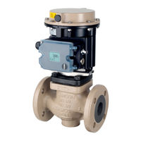
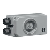
Samson 3730 Series Mounting And Operating Instructions (220 pages)
Electropneumatic positioner with pressure sensors, communication: HART
Brand:
Samson
| Category:
Valve Positioners
| Size: 19.61 MB
Table of Contents
Table of Contents
3
1 Safety Instructions and Measures
7
Notes on Possible Severe Personal Injury
10
Notes on Possible Personal Injury
10
Notes on Possible Property Damage
11
Special Instructions Concerning Explosion Protection
12
2 Markings on the Device
15
Nameplate
15
Article Code
16
Firmware Versions
18
3 Design and Principle of Operation
19
Additional Equipment
20
Communication
22
Configuration Using the TROVIS-VIEW Software
22
Technical Data
23
Dimensions in MM
29
Fixing Levels According to VDI/VDE 3845 (September 2010)
33
4 Shipment and On-Site Transport
34
Accepting the Delivered Goods
34
Removing the Packaging from the Positioner
34
Transporting the Positioner
34
Storing the Positioner
34
5 Installation
36
Installation Conditions
36
Preparation for Installation
37
Adjusting the Lever and Pin Position
37
Travel Tables
39
Direct Attachment
41
Attachment According to IEC 60534-6
45
Attachment According to VDI/VDE 3847-1
47
Attachment According to VDI/VDE 3847-2
51
Attachment to Type 3510 Micro-Flow Valve
59
Attachment to Rotary Actuators
59
Reversing Amplifier for Double-Acting Actuators
65
Mounting the Position Sensor with Direct Attachment
66
Mounting the Position Sensor with Attachment According to IEC 60534-6
67
Mounting the Position Sensor to Type 3510 Micro-Flow Valve
69
Mounting on Rotary Actuators
70
Mounting the Leakage Sensor
71
Retrofitting Inductive Limit Switch
72
Mounting Positioners with Stainless Steel Housings
73
Air Purging Function for Single-Acting Actuators
73
Connecting the Air Supply
75
Signal Pressure Connection
76
Supply Pressure
76
Signal Pressure (Output)
77
Connecting the Electrical Power Supply
79
Switching Amplifier According to en 60947-5-6
79
Establishing Communication
79
Mounting Accessories
81
6 Operation
88
Serial Interface
89
HART ® Communication
91
Dynamic HART Variables
91
7 Start-Up and Configuration
94
Determining the Fail-Safe Position
95
Adjusting the Volume Restriction Q
96
Limiting the Signal Pressure
96
Checking the Operating Range of the Positioner
97
Initializing the Positioner
98
MAX - Initialization Based on Maximum Range
101
NOM - Initialization Based on Nominal Range
102
MAN - Initialization Based on a Manually Selected OPEN Position
103
MAN2 - Initialization Based on Manually Selected End Positions
105
SUB - Substitute Calibration
106
Tuning the KP Input Filter
110
Setting Other Parameters
111
8 Operation
116
Adapting the Display Direction
116
Closed-Loop Operation (Automatic Mode)
117
Manual Mode
117
Fail-Safe Position (SAFE)
118
Performing Zero Calibration
119
Resetting the Positioner
120
Advertisement
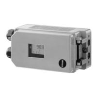
Samson 3730 Series Mounting And Operating Instructions (216 pages)
Brand:
Samson
| Category:
Valve Positioners
| Size: 27.99 MB
Table of Contents
Table of Contents
3
Safety Instructions and Measures
7
Notes on Possible Severe Personal Injury
10
Notes on Possible Personal Injury
10
Notes on Possible Property Damage
11
Special Instructions Concerning Explosion Protection
13
Markings on the Device
15
Nameplate
15
Article Code
16
Firmware Versions
18
Design and Principle of Operation
21
Mounting Versions
22
Additional Equipment
22
Communication
23
Configuration Using the TROVIS-VIEW Software
24
Technical Data
25
Dimensions in MM
31
Fixing Levels According to VDI/VDE 3845 (September 2010)
35
Shipment and On-Site Transport
37
Accepting the Delivered Goods
37
Removing the Packaging from the Positioner
37
Transporting the Positioner
37
Storing the Positioner
37
Installation
39
Installation Conditions
39
Preparation for Installation
40
Adjusting the Lever and Pin Position
40
Exchanging the Lever
40
Travel Tables
43
Positioner Attachment
44
Direct Attachment
44
Attachment According to IEC 60534-6
48
Attachment According to VDI/VDE 3847-1
50
Attachment According to VDI/VDE 3847-2
54
Attachment to Type 3510 Micro-Flow Valve
62
Attachment to Rotary Actuators
62
Reversing Amplifier for Double-Acting Actuators
68
Attachment of External Position Sensor
68
Mounting the Position Sensor with Direct Attachment
69
Mounting the Position Sensor with Attachment According to IEC 60534-6
70
Mounting the Position Sensor to Type 3510 Micro-Flow Valve
72
Mounting on Rotary Actuators
73
Mounting the Leakage Sensor
74
Retrofitting Inductive Limit Switch
75
Mounting Positioners with Stainless Steel Housings
76
Air Purging Function for Single-Acting Actuators
76
Pneumatic Connection
78
Signal Pressure Connection
79
Signal Pressure Reading
79
Supply Pressure
79
Signal Pressure (Output)
79
Electrical Connection
80
Switching Amplifier According to en 60947-5-6
83
Mounting Accessories
85
Operation
91
Serial Interface
92
HART ® Communication
94
Dynamic HART ® Variables
94
Start-Up and Configuration
97
Determining the Fail-Safe Position
98
Adjusting the Volume Restriction Q
99
Limiting the Signal Pressure
100
Checking the Operating Range of the Positioner
100
Initializing the Positioner
102
MAX - Initialization Based on Maximum Range
104
NOM - Initialization Based on Nominal Range
105
MAN - Initialization Based on a Manually Selected OPEN Position
107
Sub - Substitute Calibration
108
Setting Other Parameters
112
Adjusting Inductive Limit Switch
113
Operation
117
Adapting the Display Direction
117
Changing the Operating Mode
118
Closed-Loop Operation (Automatic Mode)
118
Manual Mode
118
Fail-Safe Position (SAFE)
119
Performing Zero Calibration
120
Samson 3730 Series Mounting And Operating Instructions (208 pages)
Electropneumatic Positioner
Brand:
Samson
| Category:
Valve Positioners
| Size: 35.3 MB
Table of Contents
Table of Contents
3
Safety Instructions and Measures
7
Notes on Possible Severe Personal Injury
10
Notes on Possible Personal Injury
10
Notes on Possible Property Damage
11
Special Instructions Concerning Explosion Protection
13
Markings on the Device
15
Nameplate
15
Article Code
16
Firmware Versions
17
Design and Principle of Operation
19
Mounting Versions
20
Additional Equipment
20
Communication
21
Configuration Using the TROVIS-VIEW Software
21
Technical Data
22
Dimensions in MM
27
Fixing Levels According to VDI/VDE 3845 (September 2010)
31
Shipment and On-Site Transport
33
Accepting the Delivered Goods
33
Removing the Packaging from the Positioner
33
Transporting the Positioner
33
Storing the Positioner
33
Installation
35
Installation Conditions
35
Preparation for Installation
36
Adjusting the Lever and Pin Position
36
Exchanging the Lever
36
Travel Tables
39
Positioner Attachment
40
Direct Attachment
40
Attachment According to IEC 60534-6
44
Attachment According to VDI/VDE 3847-1
46
Attachment According to VDI/VDE 3847-2
50
Attachment to Type 3510 Micro-Flow Valve
58
Attachment to Rotary Actuators
58
Reversing Amplifier for Double-Acting Actuators
64
Attachment of External Position Sensor
64
Mounting the Position Sensor with Direct Attachment
65
Mounting the Position Sensor with Attachment According to IEC 60534-6
66
Mounting the Position Sensor to Type 3510 Micro-Flow Valve
68
Mounting on Rotary Actuators
69
Mounting the Leakage Sensor
70
Retrofitting Inductive Limit Switch
71
Mounting Positioners with Stainless Steel Housings
72
Air Purging Function for Single-Acting Actuators
72
Pneumatic Connection
74
Signal Pressure Connection
75
Signal Pressure Reading
75
Supply Pressure
75
Signal Pressure (Output)
75
Electrical Connection
76
Switching Amplifier According to en 60947-5-6
79
Establishing Communication
79
Mounting Accessories
81
Operation
87
Start-Up and Configuration
91
Determining the Fail-Safe Position
92
Adjusting the Volume Restriction Q
93
Limiting the Signal Pressure
94
Checking the Operating Range of the Positioner
95
Initializing the Positioner
96
MAX - Initialization Based on Maximum Range
98
NOM - Initialization Based on Nominal Range
99
MAN - Initialization Based on a Manually Selected OPEN Position
101
Sub - Substitute Calibration
102
Setting Other Parameters
107
Adjusting Inductive Limit Switch
109
Operation
113
Adapting the Display Direction
113
Changing the Operating Mode
114
Closed-Loop Operation (Automatic Mode)
114
Manual Mode
114
Fail-Safe Position (SAFE)
115
Performing Zero Calibration
116
Advertisement
Samson 3730 Series Mounting And Operating Instructions (180 pages)
Electropneumatic Positioner
Brand:
Samson
| Category:
Valve Positioners
| Size: 14.34 MB
Table of Contents
Table of Contents
3
1 Safety Instructions and Measures
7
Notes on Possible Severe Personal Injury
11
Notes on Possible Personal Injury
11
Notes on Possible Property Damage
12
2 Markings on the Device
13
Nameplate
13
Article Code
14
Firmware Versions
15
3 Design and Principle of Operation
17
Mounting Versions
18
Additional Equipment
18
Communication
20
Configuration Using the TROVIS-VIEW Software
20
Device Overview and Operating Controls
20
Accessories
21
Travel Tables
26
Technical Data
27
Dimensions in MM
33
Fixing Levels According to VDI/VDE 3845 (September 2010)
37
4 Measures for Preparation
39
Unpacking
39
Transporting
39
Storage
39
5 Mounting and Start-Up
41
Mounting Position
41
Lever and Pin Position
41
Direct Attachment
44
Type 3277-5 Actuator
44
Type 3277 Actuator
46
Attachment According to IEC 60534-6
48
Attachment According to VDI/VDE 3847-1
50
Attachment According to VDI/VDE 3847-2
54
Version for Single-Acting Actuator
56
Version for Double-Acting Actuator
58
Attachment to Type 3510 Micro-Flow Valve
62
Attachment to Rotary Actuators
62
Heavy-Duty Version
64
Reversing Amplifier for Double-Acting Actuators
68
Reversing Amplifier (1079-1118 or 1079-1119)
68
Attachment of External Position Sensor
70
Mounting the Position Sensor with Direct Attachment
71
Mounting the Position Sensor with Attachment According to IEC 60534-6
73
Mounting the Position Sensor to Type 3510 Micro-Flow Valve
74
Mounting on Rotary Actuators
75
Mounting the Leakage Sensor
76
Retrofitting an Inductive Limit Switch
77
Attaching Positioners with Stainless Steel Housings
78
Air Purging Function for Single-Acting Actuators
78
Pneumatic Connections
81
Connecting the Supply Air
81
Signal Pressure Gauges
82
Supply Pressure
82
Signal Pressure (Output)
83
Electrical Connections
83
Connecting the Electrical Power
85
Switching Amplifier According to en 60947-5-6
86
Establishing Communication
86
6 Operation
89
Serial Interface
91
HART ® Communication
92
Dynamic HART ® Variables
92
7 Operating the Positioner
95
Determining the Fail-Safe Position
96
Adjusting the Volume Restriction Q
96
Adapting the Display Direction
97
Limiting the Signal Pressure
97
Checking the Operating Range of the Positioner
98
Initializing the Positioner
100
MAX - Initialization Based on Maximum Range
102
NOM - Initialization Based on Nominal Range
103
MAN - Initialization Based on a Manually Selected OPEN Position
105
MAN2 - Initialization Based on Manually Selected End Positions
106
SUB - Substitute Calibration
108
Tuning the KP Input Filter
112
Zero Calibration
113
Adjusting Inductive Limit Switch
115
Reset to Default Settings
117
Enabling and Selecting Parameters
120
Operating Modes
121
Automatic and Manual Modes
121
Fail-Safe Position (SAFE)
122
Samson 3730 Series Mounting And Operating Instructions (160 pages)
Electropneumatic Positioner With FOUNDATION fieldbus communication
Brand:
Samson
| Category:
Valve Positioners
| Size: 12.17 MB
Table of Contents
Table of Contents
3
1 Safety Instructions and Measures
7
Notes on Possible Severe Personal Injury
10
Notes on Possible Personal Injury
10
Notes on Possible Property Damage
11
2 Markings on the Device
13
Nameplate
13
Article Code
14
Firmware Versions
15
3 Design and Principle of Operation
19
Mounting Versions
20
Additional Equipment
20
Communication
21
Configuration Using the TROVIS-VIEW Software
21
Device Overview and Operating Controls
22
Accessories
23
Travel Tables
28
Technical Data
29
Dimensions in MM
35
Fixing Levels According to VDI/VDE 3845 (September 2010)
39
4 Measures for Preparation
41
Unpacking
41
Transporting
41
Storage
41
5 Mounting and Start-Up
43
Mounting Position
43
Lever and Pin Position
43
Direct Attachment
46
Type 3277-5 Actuator
46
Type 3277 Actuator
48
Attachment According to IEC 60534-6
50
Attachment According to VDI/VDE 3847-1
52
Attachment According to VDI/VDE 3847-2
56
Version for Single-Acting Actuator
58
Version for Double-Acting Actuator
60
Attachment to Type 3510 Micro-Flow Valve
64
Attachment to Rotary Actuators
64
Heavy-Duty Version
66
Reversing Amplifier for Double-Acting Actuators
70
Reversing Amplifier (1079-1118 or 1079-1119)
70
Attachment of External Position Sensor
72
Mounting the Position Sensor with Direct Attachment
73
Mounting the Position Sensor with Attachment According to IEC 60534-6
75
Mounting the Position Sensor to Type 3510 Micro-Flow Valve
76
Mounting on Rotary Actuators
77
Mounting the Leakage Sensor
78
Retrofitting an Inductive Limit Contact
79
Attaching Positioners with Stainless Steel Housings
80
Air Purging Function for Single-Acting Actuators
80
Pneumatic Connections
83
Connecting the Supply Air
83
Signal Pressure Gauges
84
Supply Pressure
84
Signal Pressure (Output)
85
Electrical Connections
85
Establishing Communication
87
6 Operation
91
7 Operating the Positioner
95
Determining the Fail-Safe Position
96
Adjusting the Volume Restriction Q
96
Adapting the Display Direction
97
Limiting the Signal Pressure
97
Checking the Operating Range of the Positioner
98
Initializing the Positioner
99
MAX - Initialization Based on Maximum Range
102
NOM - Initialization Based on Nominal Range
103
MAN - Initialization Based on a Manually Selected Range
105
Sub - Substitute Calibration
106
Zero Calibration
111
Adjusting the Inductive Limit Contact
112
Reset to Default Settings
114
Enabling and Selecting Parameters
114
Operating Modes
116
Automatic and Manual Modes
116
Fail-Safe Position (SAFE)
117
Samson 3730 Series Mounting And Operating Instructions (140 pages)
Electropneumatic
Brand:
Samson
| Category:
Valve Positioners
| Size: 2.78 MB
Table of Contents
Table of Contents
3
1 Important Safety Instructions
8
2 Article Code
9
3 Design and Principle of Operation
10
Application Type
11
Additional Equipment
12
Configuration Using TROVIS-VIEW Software
13
Technical Data
14
4 Attachment to the Control Valve - Mounting Parts and Accessories
18
Direct Attachment
20
Type 3277-5 Actuator
20
Type 3277 Actuator
22
Attachment According to IEC 60534-6 (NAMUR)
24
Attachment to Type 3510 Micro-Flow Valve
26
Attachment to Rotary Actuators
28
Heavy-Duty Version
30
Reversing Amplifier for Double-Acting Actuators
32
Reversing Amplifier (1079-1118 or 1079-1119)
32
Attaching an External Position Sensor
34
Mounting the Position Sensor with Direct Attachment
34
Mounting the Position Sensor with Attachment According to IEC 60534-6
36
Mounting the Position Sensor to Type 3510 Micro-Flow Valve
37
Mounting the Position Sensor to Rotary Actuators
38
Attaching Positioners with Stainless Steel Housings
39
Air Purging Function for Single-Acting Actuators
39
Mounting Parts and Accessories
40
5 Connections
44
Pneumatic Connections
44
Signal Pressure Gauges
44
Supply Pressure
44
Signal Pressure (Output)
45
Electrical Connections
45
Switching Amplifiers
47
6 Operator Controls and Readings
48
Serial Interface
50
7 Start-Up - Settings
50
Defining the Valve Closed Position
51
Setting the Volume Restriction Q
51
Adapting the Display
52
Limiting the Signal Pressure
52
Checking the Operating Range of the Positioner
53
Initialization
54
MAX - Initialization Based on Maximum Range
55
NOM - Initialization Based on Nominal Range
56
MAN - Initialization Based on a Manually Selected Range
57
Sub Substitute Calibration
59
Zero Calibration
62
Performing Settings for Open/Close Valves
63
Reset to Default Values
65
8 Operation
66
Enabling and Selecting Parameters
66
Operating Modes
67
Automatic and Manual Modes
67
Fail-Safe Position (SAFE)
68
Malfunction/Maintenance Alarm
68
Confirming Error Messages
69
9 Adjusting the Limit Switch
70
Retrofitting an Inductive Limit Switch
72
10 Maintenance
73
Samson 3730 Series Mounting And Operating Instructions (140 pages)
Electropneumatic Positioner
Brand:
Samson
| Category:
Valve Positioners
| Size: 3.63 MB
Table of Contents
Table of Contents
3
Important Safety Instructions
9
Article Code
10
Design and Principle of Operation
11
Application Type
12
Additional Equipment
13
Communication
14
Configuration Using TROVIS-VIEW Software
14
Technical Data
15
Attachment to the Control Valve - Mounting Parts and Accessories
18
Direct Attachment
20
Type 3277-5 Actuator
20
Type 3277 Actuator
22
Attachment According to IEC 60534-6 (NAMUR)
24
Attachment to Type 3510 Micro-Flow Valve
26
Attachment to Rotary Actuators
28
Reversing Amplifier for Double-Acting Actuators
30
Pressure Gauge Attachment
30
Attaching an External Position Sensor
32
Mounting the Position Sensor with Direct Attachment
32
Mounting the Position Sensor with Attachment According to IEC 60534-6
34
Mounting the Position Sensor to Type 3510 Micro-Flow Valve
35
Mounting the Position Sensor to Rotary Actuators
36
Attaching Positioners with Stainless Steel Housings
37
Air Purging Function for Single-Acting Actuators
37
Required Mounting Parts and Accessories
38
Connections
42
Pneumatic Connections
42
Signal Pressure Gauges
42
Supply Pressure
42
Signal Pressure (Output)
43
Electrical Connections
43
Switching Amplifiers
45
Establishing Communication
46
Operator Controls and Readings
48
Serial Interface
50
HART ® Communication
50
Start-Up - Settings
51
Determining the Fail-Safe Position
51
Setting the Volume Restriction Q
52
Adapting the Display
52
Limiting the Signal Pressure
53
Checking the Operating Range of the Positioner
53
Initialization
54
MAX - Initialization Based on Maximum Range
56
NOM - Initialization Based on Nominal Range
57
MAN - Initialization Based on a Manually Selected Range
58
Sub Substitute Calibration
59
Zero Calibration
62
Performing Settings for Open/Close Valves
63
Reset to Default Values
65
Operation
66
Enabling and Selecting Parameters
66
Operating Modes
67
Automatic and Manual Modes
67
Samson 3730 Series Mounting And Operating Instructions (132 pages)
Type 3730-6 Electropneumatic Positioner
Brand:
Samson
| Category:
Controller
| Size: 3.75 MB
Table of Contents
Table of Contents
3
1 Important Safety Instructions
7
2 Article Code
9
3 Design and Principle of Operation
10
Safety Function (SIL)
12
Valve Diagnostics
12
Communication
13
Configuration Using the TROVIS-VIEW Software
13
Additional Equipment
13
Technical Data
15
4 Attachment to the Control Valve - Mounting Parts and Accessories
21
Direct Attachment
23
Type 3277-5 Actuator
23
Type 3277 Actuator
25
Attachment According to IEC 60534-6
27
Attachment According to VDI/VDE 3847
29
Attachment to Type 3510 Micro-Flow Valve
35
Attachment to Rotary Actuators
35
Heavy-Duty Version
37
Reversing Amplifier for Double-Acting Actuators
39
Reversing Amplifier (1079-1118 or 1079-1119)
41
Attachment of External Position Sensor
43
Mounting the Position Sensor with Direct Attachment
43
Mounting the Position Sensor with Attachment According to IEC 60534-6
45
Mounting the Position Sensor to Type 3510 Micro-Flow Valve
46
Mounting on Rotary Actuators
47
Mounting the Leakage Sensor
49
Attaching Positioners with Stainless Steel Housings
50
Air Purging Function for Single-Acting Actuators
50
Required Mounting Parts and Accessories
52
5 Connections
58
Pneumatic Connections
58
Signal Pressure Gauges
58
Supply Pressure
58
Signal Pressure (Output)
59
Electrical Connections
59
Switching Amplifier
61
Establishing Communication
62
6 Operating Controls and Readings
64
Serial Interface
67
HART ® Communication
67
Dynamic HART ® Variables
67
7 Start-Up and Settings
69
Determining the Fail-Safe Position
69
Adjusting the Volume Restriction Q
70
Adapting the Display Direction
70
Limiting the Signal Pressure
70
Checking the Operating Range of the Positioner
71
Initialization
72
MAX - Initialization Based on Maximum Range
74
NOM - Initialization Based on Nominal Range
75
MAN - Initialization Based on a Manually Selected OPEN Position
76
MAN2 - Initialization Based on Manually Selected End Positions
77
SUB - Substitute Calibration
78
Tuning the KP Input Filter
81
Zero Calibration
81
Reset to Default Settings
82
Samson 3730 Series Mounting And Operating Instructions (132 pages)
Electropneumatic Positioner with HART communication
Brand:
Samson
| Category:
Valve Positioners
| Size: 3.06 MB
Table of Contents
Table of Contents
2
1 Design and Principle of Operation
8
Communication
9
Additional Equipment
9
Technical Data
11
2 Attachment to the Control Valve - Mounting Parts and Accessories
14
Direct Attachment
18
Type 3277-5 Actuator
18
Type 3277 Actuator
20
Attachment According to IEC 60534-6
22
Attachment to Type 3510 Micro-Flow Valve
24
Attachment to Rotary Actuators
26
Reversing Amplifier for Double-Acting Actuators
28
Pressure Gauge Attachment
28
Attaching an External Position Sensor
30
Mounting the Position Sensor with Direct Attachment
30
Mounting the Position Sensor with Attachment According to IEC 60534-6
32
Mounting the Position Sensor to Type 3510 Micro-Flow Valve
33
Mounting the Position Sensor to Rotary Actuators
34
Attaching Positioners with Stainless Steel Housings
36
Air Purging Function for Single-Acting Actuators
36
3 Connections
38
Pneumatic Connections
38
Signal Pressure Gauges
38
Supply Pressure
38
Electrical Connections
40
Switching Amplifiers
42
Establishing Communication
42
4 Operation
44
Operator Controls and Display
44
Enabling and Selecting Parameters
46
Operating Modes
47
Automatic and Manual Operating Modes
47
SAFE - Fail-Safe Position
48
5 Start-Up and Settings
48
Determining the Fail-Safe Position
49
Setting the Volume Restriction Q
49
Adapting the Display
49
Limiting the Signal Pressure
50
Checking the Operating Range of the Positioner
50
Initialization
51
Initialization Modes
53
Fault/Failure
59
Zero Calibration
60
Reset to Default Values
61
Start-Up Via Local Interface (SSP)
61
Start-Up over HART ® Communication
61
6 Status and Diagnostic Alarms
62
Standard EXPERT Diagnostics
62
Extended EXPERT + Diagnostics
63
Classification of the Status Alarms and the Condensed Status
63
7 Adjusting the Limit Switch
66
Samson 3730 Series Operating Instructions Manual (120 pages)
Electropneumatic Positioner EXPERTplus Valve Diagnostics
Brand:
Samson
| Category:
Valve Positioners
| Size: 3.54 MB
Table of Contents
Table of Contents
3
1 Description
7
General
7
Start-Up
9
Diagnostic Functions
10
Type of Application
11
Assessment
11
2 Monitoring
13
Status Messages
13
Resetting Status Messages
13
Condensed State
17
Logging
18
3 Data Logger
21
Permanent Data Logging
21
Triggered Data Logging
22
Triggered by Condensed State
22
Triggered by Set Point, Valve Position, Set Point Deviation or Signal Pressure
23
Triggered by Binary Input
24
Triggered by Internal Solenoid Valve/Forced Venting
25
Triggered by Set Point or Internal Solenoid Valve/Forced Venting
25
4 Valve Signature
27
Reference Graphs
28
Analysis and Monitoring
28
Valve Signature, Signal Pressure(X)
29
Analysis and Monitoring
30
Course of Supply Pressure
31
Analysis and Monitoring
32
Valve Signature, Friction(X)
33
Analysis and Monitoring
34
Resetting Single Status Messages
34
5 On/Off Valve
37
Diagnostics for On/Off Valve
38
Analysis and Monitoring
39
Resetting Single Status Messages
40
6 Valve Position X Histogram
41
Analysis and Monitoring
42
Resetting Single Status Messages
42
7 Set Point Deviation E Histogram
44
Analysis and Monitoring
45
Resetting Single Status Messages
46
8 Cycle Counter Histogram
49
Analysis and Monitoring
50
Resetting Single Status Messages
50
9 Leakage Sensor
53
Start-Up of the Leakage Sensor
54
Manufacturer Reference
54
Process Reference
57
Short-Term Monitoring
62
Resetting Single Status Messages
63
Long-Term Monitoring
63
Sound Level(X)
64
Resetting Single Status Messages
64
10 Course of End Position
67
Analysis and Monitoring
68
Resetting Single Status Messages
68
Samson 3730 Series Mounting And Operating Instructions (124 pages)
Electropneumatic Positioner with PROFIBUS-PA communication
Brand:
Samson
| Category:
Valve Positioners
| Size: 3.3 MB
Table of Contents
Table of Contents
3
Important Safety Instructions
6
Article Code
7
Design and Principle of Operation
8
Additional Equipment
9
Communication
10
Configuration Using TROVIS-VIEW Software
10
Technical Data
11
Attachment to the Control Valve - Mounting Parts and Accessories
14
Direct Attachment
16
Type 3277-5 Actuator
16
Type 3277 Actuator
18
Attachment According to IEC 60534-6 (NAMUR)
20
Attachment According to VDI/VDE 3847
22
Attachment to Type 3510 Micro-Flow Valve
28
Attachment to Rotary Actuators
30
Heavy-Duty Version
32
Reversing Amplifier for Double-Acting Actuators
34
Reversing Amplifier (1079-1118 or 1079-1119)
34
Attaching an External Position Sensor
36
Mounting the Position Sensor with Direct Attachment
36
Mounting the Position Sensor with Attachment According to IEC 60534-6
38
Mounting the Position Sensor to Type 3510 Micro-Flow Valve
39
Mounting the Position Sensor to Rotary Actuators
40
Attaching Positioners with Stainless Steel Housings
41
Air Purging Function for Single-Acting Actuators
41
Mounting Parts and Accessories
42
Connections
47
Pneumatic Connections
47
Signal Pressure Gauges
47
Supply Pressure
47
Signal Pressure (Output)
48
Electrical Connections
48
Establishing Communication
51
Operator Controls and Readings
53
Start-Up - Settings
56
Defining the Valve Closed Position
56
Setting the Volume Restriction Q
57
Adapting the Display
57
Limiting the Signal Pressure
58
Checking the Operating Range of the Positioner
58
Initialization
60
MAX - Initialization Based on Maximum Range
61
NOM - Initialization Based on Nominal Range
62
MAN - Initialization Based on a Manually Selected Range
63
Sub Substitute Calibration
65
Zero Calibration
68
Reset to Default Values
68
Start-Up Via Local Interface (SSP)
69
Setting the Bus Address
69
Operation
70
Enabling and Selecting Parameters
70
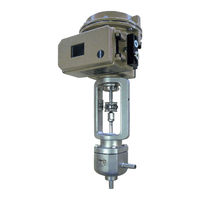
Samson 3730 Series Mounting And Operating Instructions (104 pages)
Aseptic Angle Valve with USP-VI diaphragm, Valve with Pneumatic Actuator and Positioner, Valve combined with Pneumatic Piston Actuator and Positioner
Brand:
Samson
| Category:
Control Unit
| Size: 6.86 MB
Table of Contents
Table of Contents
3
Safety Instructions and Measures
7
Notes on Possible Severe Personal Injury
11
Notes on Possible Personal Injury
11
Notes on Possible Property Damage
13
Warnings on the Device
14
Markings on the Device
17
Body Inscription
17
Material Identification Number
17
Actuator Nameplate
17
Label When an Adjustable Packing Is Installed
17
Design and Principle of Operation
19
Fail-Safe Action
22
Versions
22
Additional Fittings
23
Valve Accessories
23
Technical Data
23
Shipment and On-Site Transport
29
Accepting the Delivered Goods
29
Removing the Packaging from the Valve
29
Transporting and Lifting the Valve
29
Transporting the Valve
31
Lifting the Valve
31
Storing the Valve
33
Installation
35
Installation Conditions
35
Preparation for Installation
36
Mounting the Device
37
Mounting the Actuator Onto the Valve
38
Installing the Valve into the Pipeline
40
Testing the Installed Valve
41
Leak Test
42
Travel Motion
43
Fail-Safe Position
43
Pressure Test
43
Start-Up
45
Operation
47
Normal Operation
48
Manual Operation
48
CIP (Cleaning-In-Place)
48
SIP (Sterilization-In-Place)
48
Malfunctions
49
Troubleshooting
49
Emergency Action
51
Servicing
53
Periodic Testing
55
Checking the Extent of Servicing
55
Preparing the Valve for Service Work
56
Installing the Valve after Service Work
56
Service Work for Version with Type 3271 or Type 3277 Actuator
56
Replacing the Packing (Micro-Flow Valve Version Only)
56
Replacing the Diaphragm and Plug
58
Service Work for Version with Type 3379 Actuator
60
Replacing the Packing (Micro-Flow Valve Version Only)
62
Samson 3730 Series Mounting And Operating Instructions (76 pages)
Electropneumatic Actuator
Brand:
Samson
| Category:
Controller
| Size: 7.26 MB
Table of Contents
Table of Contents
3
1 Safety Instructions and Measures
5
Notes on Possible Severe Personal Injury
8
Notes on Possible Personal Injury
9
Notes on Possible Property Damage
10
Warnings on the Device
12
2 Markings on the Device
13
Actuator Nameplate
13
3 Design and Principle of Operation
15
Operating Direction
15
Signal Pressure Routing
18
Fail-Safe Action
18
Actuator Stem Extends
18
Actuator Stem Retracts
19
Mounting Types
19
Versions
21
Accessories
21
Technical Data
21
4 Shipment and On-Site Transport
25
Accepting the Delivered Goods
25
Removing the Packaging from the Actuator
25
Transporting and Lifting the Actuator
25
Transporting the Actuator
25
Lifting the Actuator
26
Storing the Actuator
26
5 Installation
27
Preparation for Installation
27
Mounting the Actuator
27
Mounting the Actuator Onto the Valve
28
Connections
32
6 Start-Up
33
Spring Compression
34
Tensioning the Springs
34
Increasing the Actuator Thrust
35
Adapting the Travel Range
35
7 Operation
37
Throttling Service
37
On/Off Service
38
Additional Notes Concerning Operation
38
8 Malfunctions
39
Troubleshooting
39
Emergency Action
40
9 Servicing and Conversion
41
Periodic Testing
43
Service Work Preparations
43
Installing the Valve after Service Work
43
Service Work
46
Replacing the Diaphragm
46
Replacing the Actuator Stem Seals
48
Conversion Work
52
Reversing the Direction of Action
52
Ordering Spare Parts and Operating Supplies
52
Samson 3730 Series Mounting And Operating Instructions (72 pages)
Electropneumatic Positioner
Brand:
Samson
| Category:
Valve Positioners
| Size: 1.94 MB
Table of Contents
Table of Contents
2
1 Important Safety Instructions
6
2 Article Code
7
3 Design and Principle of Operation
8
Technical Data
10
4 Attachment to the Control Valve - Mounting Parts and Accessories
12
Direct Attachment
14
Type 3277-5 Actuator
14
Type 3277 Actuator
16
Attachment According to IEC 60534-6
18
Attachment According to VDI/VDE 3847
20
Attachment to Type 3510 Micro-Flow Valve
20
Attachment to Rotary Actuators
22
Heavy-Duty Version
24
Reversing Amplifier for Double-Acting Actuators
26
Reversing Amplifier (1079-1118 or 1079-1119)
26
Attaching Positioners with Stainless Steel Housings
28
Air Purging Function for Single-Acting Actuators
28
Mounting Parts and Accessories
29
5 Connections
33
Pneumatic Connections
33
Signal Pressure Gauges
34
Supply Pressure
34
Electrical Connections
35
Switching Amplifier
37
6 Operation
38
Operator Controls
38
7 Start-Up
39
Setting the Volume Restriction Q
40
Adapting the Display
40
Entering the Opening Direction
40
Setting Other Parameters
41
Initialization
41
Faults
43
Zero Calibration
43
Reset
44
Manual Adjustment
44
8 Code List
45
9 Maintenance
49
10 Servicing Explosion-Protected Devices
49
11 Dimensions in MM
51
Fixing Levels According to VDI/VDE 3845 (September 2010)
53
Test Certificates
54
Samson 3730 Series Mounting And Operating Instructions (48 pages)
Electropneumatic Positioner
Brand:
Samson
| Category:
Valve Positioners
| Size: 0.85 MB
Table of Contents
Table of Contents
2
1 Design and Principle of Operation
6
2 Attachment to the Control Valve - Mounting Parts and Accessories
8
Direct Attachment
12
Type 3277-5 Actuator
12
Type 3277 Actuator
14
Attachment According to IEC 60534-6
16
Attachment to Type 3510 Micro-Flow Valve
18
Attachment to Rotary Actuators
20
Reversing Amplifier for Double-Acting Actuators
22
3 Connections
24
Pneumatic Connections
24
Signal Pressure Gauges
24
Supply Pressure
24
Electrical Connections
26
4 Operation
28
Operator Controls
28
5 Start-Up
29
Setting the Volume Restriction Q
29
Adapting the Display
30
Determining the Fail-Safe Position
30
Setting Other Parameters
30
Initialization
31
Faults
32
Zero Calibration
33
6 Code List
34
7 Maintenance
38
8 Servicing Explosion-Protected Devices
38
9 Dimensions in MM
39
Test Certificates
40
Samson 3730 Series Mounting And Operating Instructions (20 pages)
Electropneumatic Positioner ESD Version, With HART communication
Brand:
Samson
| Category:
Valve Positioners
| Size: 0.35 MB
Table of Contents
Table of Contents
2
1 Description
3
General
3
ESD Functions
4
Presetting the Positioner
5
Converting TROVIS-VIEW 3
5
Unlocking the Positioner
5
Changing the Graph Settings in TROVIS-VIEW 3
6
2 ESD Functions
7
Changing ESD Parameters and Starting the Partial Stroke Test
11
On-Site Operation
12
Analyzing Measured Data
12
Condensed State
13
Measured Data
13
Resetting ESD
14
List of ESD Parameters
14
3 EXPERT + Test Functions
17
4 Notes on Applications
18
Advertisement
Related Products
Samson 3730-2
Samson FOUNDATION 3730-5
Samson TROVIS 3730-1
Samson 3730-4
Samson foundation 3787
Samson 3725 series
Samson TROVIS 3730-3
Samson 3767
Samson 3730-6
Samson 3434-1
Samson Categories
Controller
Control Unit
Microphone
Valve Positioners
Speakers
More Samson Manuals
Login
Sign In
OR
Sign in with Facebook
Sign in with Google
Upload manual
Upload from disk
Upload from URL