Samson 3730 Series Mounting And Operating Instructions
Electropneumatic positioner with profibus-pa communication
Hide thumbs
Also See for 3730 Series:
- Mounting and operating instructions (220 pages) ,
- Operating instructions manual (120 pages) ,
- Mounting and operating instructions (208 pages)

Related Manuals for Samson 3730 Series


Summary of Contents for Samson 3730 Series
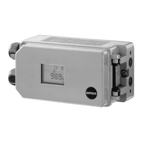
- Page 1 Series 3730 Type 3730-4 Electropneumatic Positioner with PROFIBUS-PA communication Fig. 1 · Type 3730-4 Mounting and Operating Instructions EB 8384-4 EN (1300-1613) Firmware version 1.52 Edition February 2015 EB + CD...
- Page 2 Definitions of the signal words used in these instructions DANGER! NOTICE indicates a hazardous situation which, if not indicates a property damage message. avoided, will result in death or serious injury. Note: Supplementary explanations, information and tips WARNING! indicates a hazardous situation which, if not avoided, could result in death or serious inju- EB 8384-4 EN...
-
Page 3: Table Of Contents
Contents Contents Page Important safety instructions ..... . 6 Article code ......7 Design and principle of operation. - Page 4 Contents Adapting the display......57 Limiting the signal pressure..... . . 58 Checking the operating range of the positioner .
- Page 5 Revisions to the communication firmware are listed in the Configuration Manual KH 8384-4 EN. The Configuration Manual is included on the enclosed CD-ROM and on the SAMSON website. Note: The functions of EXPERTplus valve diagnostics are described in the Mounting and Operating Instructions EB 8389 EN.
-
Page 6: Important Safety Instructions
Important safety instructions Important safety instructions For your own safety, follow these instructions concerning the mounting, start-up and opera- tion of the positioner: The positioner is to be mounted, started up or operated only by trained and experienced personnel familiar with the product. According to these Mounting and Operating Instructions, trained personnel refers to individuals who are able to judge the work they are assigned to and recognize possible dangers due to their specialized training, their knowledge and experience as... -
Page 7: Article Code
Article code Article code x x x 0 x 0 x x 1 x 0 0 x 0 x x Positioner Type 3730-4 With LCD and autotune, PROFIBUS-PA Explosion protection ohne ATEX: II 2G Ex ia IIC T6; II 2D Ex tb IIIC T80°C IP66 CSA: Ex ia IIC T6;... -
Page 8: Design And Principle Of Operation
Design and principle of operation When a set point deviation occurs, the actu- Design principle ator is pressurized or vented. If required, the operation changes in the signal pressure can be slowed down by a connectable Q restriction. The electropneumatic positioner is attached The signal pressure supplied to the actuator to pneumatic control valves. -
Page 9: Additional Equipment
The positioner is suitable for the following types of attachment using the corresponding Inductive limit switch accessories: Direct attachment to SAMSON The rotary shaft of the positioner carries an Type 3277 Actuator: section 4.1 adjustable tag which actuates the installed Attachment to actuators according to proximity switch. -
Page 10: Communication
The device-specific module for Type 3730-4 can be downloaded free of charge from the SAMSON website (Services > Software > TROVIS-VIEW). Additional information on TROVIS-VIEW (e.g. system requirements) can found on the SAMSON website and in the Data Sheet T 6661 EN. EB 8384-4 EN... -
Page 11: Technical Data
Certified DTM acc. to FDT Specification 1.2 for integration of the device into suitable FDT framework applications · Other integrations, e.g. EDD in SIMATIC PDM Local Over SAMSON SSP interface and serial interface adapter Software requirements SAMSON TROVIS-VIEW with database module 3730-4... - Page 12 Design and principle of operation Type 3730-4 Positioner (technical data in test certificates additionally apply for explosion-protected devices) –20 to +80 °C for all versions Permissible ambient –45 to +80 °C with metal cable gland temperature –25 to +80 °C with inductive limit switch (SJ2-S1N) and metal cable gland The limits in test certificate additionally apply for explosion-protected devices.
- Page 13 Design and principle of operation Materials Die-cast aluminum EN AC-AlSi12(Fe) (EN AC-44300) acc. to DIN EN 1706; Housing chromated and powder paint coated · Special version: stainless steel 1.4581 External parts Stainless steel 1.4571 and 1.4301 Cable gland Black polyamide, M20x1.5 Weight Approx.
-
Page 14: Attachment To The Control Valve - Mounting Parts And Accessories
The positioner is standard equipped with the The positioner is suitable for the following lever M (pin position 35). types of attachment: Direct attachment to SAMSON Type 3277 Actuator Attachment to actuators according to IEC 60534-6 (NAMUR) Attachment according to VDI/VDE 3847... - Page 15 [cm²] [mm] Min. Travel Max. 25.0 120/240/175/350 35.0 355/700/750 10.0 50.0 Attachment according to IEC 60534-6 (NAMUR) SAMSON valves/Type 3271 Actuator Adjustment range at positioner Required Assigned Other valves/actuators Actuator size Rated travel lever pin position [cm²] [mm] min. Travel max.
-
Page 16: Direct Attachment
Attachment to the control valve – Mounting parts and accessories Direct attachment tion. Make sure that the bonded gasket (14) points towards the actuator yoke. 4.1.1 Type 3277-5 Actuator 5. 15 mm travel: Keep the follower pin (2) at lever M (1) on the back of the Refer to Table 1 on page 42 for the required positioner in the pin position 35 (deliv- mounting parts as well as the accessories. - Page 17 Attachment to the control valve – Mounting parts and accessories Lever Symbols Switchover plate (9) 1.1 Nut 1.2 Disk spring Actuator stem Follower pin extends Follower clamp Attachment left Attachment right Screw plug Stopper Connecting plate Actuator stem 6.1 Seal rings retracts Pressure gauge bracket Press.
-
Page 18: Type 3277 Actuator
Attachment to the control valve – Mounting parts and accessories 4.1.2 Type 3277 Actuator (3). Adjust the lever (1) correspondingly and open the positioner cover to hold Refer to Table 2 on page 43 or the required the positioner shaft in position at the cap mounting parts as well as the accessories or the switch (Fig. - Page 19 Attachment to the control valve – Mounting parts and accessories Lever Connection block 12.1 Screw Disk spring 12.2 Stopper or connection for external piping Follower pin 10 14 Switch plate Follower clamp Gasket Cover plate Formed seal Cover 11 11.1 Gasket 11.1 Vent plug Lever M...
-
Page 20: Attachment According To Iec 60534-6 (Namur)
Attachment to the control valve – Mounting parts and accessories Attachment according to 3. Mount connecting plate (6) or pressure gauge bracket (7) with pressure gauges IEC 60534-6 (NAMUR) (8) on the positioner, making sure both Refer to Table 3 on page 44 for the required seal rings (6.1) are seated properly. - Page 21 Attachment to the control valve – Mounting parts and accessories Attachment to rod-type yoke Rod diameter 20 to 35 mm Attachment to NAMUR rib Additional bracket for actuators with 2800 cm and travel ≥ 60 mm Lever Lever XL and L 14.1 Disk spring Follower pin...
-
Page 22: Attachment According To Vdi/Vde 3847
Attachment to the control valve – Mounting parts and accessories Attachment according to 1. Place follower clamp (3) on the actuator stem, align and screw tight so that the VDI/VDE 3847 mounting screw is located in the groove Type 3730-4xxxxxxxx0x0060xx and of the actuator stem. - Page 23 Attachment to the control valve – Mounting parts and accessories View from below 13.1 17.1 17.2 18 18.1 11.1 12.1 Exh. 6.2 6.1 Lever Connecting plate 1.1 Nut 12.1 Seal 1.2 Disk spring Adapter block Follower pin 13.1 Screws Follower clamp Turnboard Screw plug 17.1 Formed seal...
- Page 24 Attachment to the control valve – Mounting parts and accessories 7. Insert screws (13.1) through the middle 12. Place the positioner on the adapter block holes of the adapter block (13). (13) in such a manner that the follower 8. Place the connecting plate (12) together pin (2) rests on the top of the follower with the seal (12.1) onto the screws clamp (3).
- Page 25 Attachment to the control valve – Mounting parts and accessories Attachment to NAMUR rib (see Fig. 9) Fasten the NAMUR connection block (10) directly into the existing yoke bore Refer to Table 4 on page 44 for the required using the screw and toothed lock washer mounting parts as well as the accessories.
- Page 26 Attachment to the control valve – Mounting parts and accessories 7. Mount the blank plate (18) to the turnboard (17) using the screws (18.1) Make sure that the seals are correctly seated. Note: A solenoid valve can also be mounted in place of the blank plate (18).
- Page 27 Attachment to the control valve – Mounting parts and accessories View from below 13.1 17.1 17.2 18.1 Exh. Lever Adapter block 14.1 1.1 Nut 13.1 Screws 1.2 Spring disk Bolt Follower pin 14.1 Screws Follower plate U-bolt 3.1 Follower plate Bracket Turnboard Screw plug...
-
Page 28: Attachment To Type 3510 Micro-Flow Valve
Attachment to the control valve – Mounting parts and accessories Attachment to Type 3510 Move lever once all the way as far as it will go in both directions. Micro-flow Valve 10. Place positioner on the bracket (10) in Refer to Table 3 on page 44 for the required such a manner that the follower pin mounting parts as well as the accessories slides into the groove of the clamp (3). - Page 29 Attachment to the control valve – Mounting parts and accessories 12.1 11.1 10.1 Lever Disk spring Follower pin Note: Always use the connecting plate (6) included in the accessories to connect Follower plate supply and output. Connecting clamp Never screw threaded parts directly into Seal rings the housing.
-
Page 30: Attachment To Rotary Actuators
Prior to attaching the positioner to the bore for pin position 90°. SAMSON Type 3278 Rotary Actuator, mount the associated adapter (5) to the free 7. Place positioner on the top pair of end of the rotary actuator shaft. - Page 31 Attachment to the control valve – Mounting parts and accessories (7, 8) 10.1 Note: Always use the connecting 80 mm plate (6) included in the accessories to connect supply and output. Never screw threaded 130 mm parts directly into the housing.
-
Page 32: Heavy-Duty Version
(11) underneath, if der no.1400-6964) into the signal pres- necessary. sure output of the positioner (or the out- 2. For SAMSON Type 3278 and VETEC put of the pressure gauge bracket or S160 Rotary Actuator, screw the adapter connecting plate). - Page 33 Actuator shaft or adapter 5.1 Adapter 10.1 10.1 Attachment acc. to VDE/VDI 3845 (2010) level 1, size AA1 to AA4, section 15.1 SAMSON Type 3278 VETEC S160, VETEC R Fig. 14 · Attachment to rotary actuators (heavy-duty version) EB 8384-4 EN...
-
Page 34: Reversing Amplifier For Double-Acting Actuators
3. Insert the gasket (1.2) into the recess of amplifier, e.g. the SAMSON Type 3710 Re- the reversing amplifier and push both versing Amplifier (see Mounting and Oper- the hollowed special screws (1.1) into ating Instructions EB 8392 EN). - Page 35 Attachment to the control valve – Mounting parts and accessories From the positioner Output 38 Supply 9 Control signals to the actuator Reversing amplifier Connecting plate 1.1 Special screws 6.1 O-rings 6.2 Screws 1.2 Gasket 1.3 Special nuts 1.4 Rubber seal 1.5 Sealing plug 1.6 Filter Fig.
-
Page 36: Attaching An External Position Sensor
Attachment to the control valve – Mounting parts and accessories Operation and setting are described in Attaching an external sections 7 and 8. position sensor – Since 2009, the back of the position sen- sor (20) is fitted with two pins acting as Refer to Table 7 on page 46 for the mount- mechanical stops for the lever (1). - Page 37 Attachment to the control valve – Mounting parts and accessories version "Actuator stem extends". pin (2) from the travel table on page 15. For the fail-safe position "Actuator stem re- The positioner is delivered with lever M tracts" the connection on the top diaphragm in pin position 35 on the sensor.
-
Page 38: Mounting The Position Sensor With Attachment According To Iec 60534-6
Attachment to the control valve – Mounting parts and accessories of the follower clamp (3). It must rest on Unthread the nut (1.1) and remove the it with spring force. lever together with the disk spring (1.2) Screw tight the mounting plate (21) onto from the sensor shaft. -
Page 39: Mounting The Position Sensor To Type 3510 Micro-Flow Valve
Attachment to the control valve – Mounting parts and accessories the follower plate (3) and fix with the 2. Screw the position sensor (20) onto the screws (14.1). bracket (21). 5. Place the bracket with the sensor at the 3. Select the lever S (1) from the accesso- NAMUR rib in such a manner that the ries and screw the follower pin (2) into follower pin (2) rests in the slot of the fol-... -
Page 40: Mounting The Position Sensor To Rotary Actuators
Attachment to the control valve – Mounting parts and accessories 4.7.4 Mounting the position 4. Place the lever (1) and disk spring (1.2) on the sensor shaft. sensor to rotary actuators Place the lever (1) in mid-position and For the required mounting parts and the ac- hold it in place. -
Page 41: Attaching Positioners With Stainless Steel Housings
Attachment to the control valve – Mounting parts and accessories Attaching positioners with Air purging function for stainless steel housings single-acting actuators Positioners with stainless steel housings re- The exhaust air from the positioner is di- quire mounting parts that are completely verted to the actuator spring chamber to made of stainless steel or free of aluminum. -
Page 42: Mounting Parts And Accessories
Attachment to the control valve – Mounting parts and accessories over piping. An adapter available as an ac- Should other valve accessories be used cessory is used for this purpose: which vent the actuator (e.g. solenoid valve, volume booster, quick exhaust valve), this exhaust air must also be included in the Threaded bushing G ¼... - Page 43 Attachment to the control valve – Mounting parts and accessories Table 2 · Direct attachment to Type 3277 (Fig. 5) Order no. Standard version for actuators with 175, 240, 350, 355, 700, 750 cm² 1400-7453 Mounting parts Version compatible with paint for actuators with 175, 240, 350, 355, 700, 750 cm² 1402-0941 1402-0970 Steel...
- Page 44 Mounting kit for attachment to SAMSON Type 3271 or non-SAMSON actuators 1402-0869 parts Travel pick-off for valve travel up to 100 mm 1402-0177 Travel pick-off for 100 to 200 mm valve travel (SAMSON Type 3271 only) 1402-0178 EB 8384-4 EN...
- Page 45 1400-9873 Attachment for SAMSON Type 3278 with 160/320 cm², CrNiMo steel bracket 1400-7614 Attachment for SAMSON Type 3278 with 160 cm² and for VETEC Type S160, Type R 1400-9245 and Type M, heavy-duty version Attachment for SAMSON Type 3278 with 320 cm² and for VETEC Type S320,...
- Page 46 Bracket surface corresponds to level 2, heavy-duty version 1400-9974 SAMSON Type 3278 with 160 cm² (also for VETEC Type S160 and Type R), 1400-9385 heavy-duty version SAMSON Type 3278 with 320 cm² and for VETEC Type S320, heavy-duty...
-
Page 47: Connections
Connections observed. Connections Blow through all air pipes and hoses tho- roughly prior to connecting them. WARNING! Mount the positioner, keeping the following sequence: If the positioner is attached directly to the 1. Remove protective film from pneumatic Type 3277 Actuator, the connection of the connections. -
Page 48: Signal Pressure (Output)
Connections Actuator stem retracts FE (AIR TO CLOSE) Electrical connections Fail-open (for globe and angle valves): For tight-closing valves, the maximum signal DANGER! pressure pst is roughly estimated as fol- Risk of electric shock and/or lows: the formation of an explosive atmosphere! ⋅... - Page 49 Connections In particular, the radial thickness of the con- Cable entries ductor insulation for common insulation ma- The cable entry with M20 x 1.5 cable gland, terials, such as polyethylene, must have a 6 to 12 mm clamping range. minimum radial thickness of 0.2 mm. There is a second M20 x 1.5 threaded bore The diameter of an individual wire in a in the housing that can be used for addi-...
- Page 50 Connections Bus line Limit switch Route the two-wire bus line to the screw ter- For operation of the limit switches, switching minals marked "IEC 1158-2", whereby no amplifiers have to be connected in the out- polarity has to be observed. put circuit.
-
Page 51: Establishing Communication
Connections Solenoid valve (forced venting function) 5.2.1 Establishing communication For positioners fitted with the optional sole- The communication structure between the noid valve for the forced venting function, a controller, logic solvers (PLC) or automation voltage of 24 V DC must be connected to system, or between a PC or work station the relevant terminals +81 and –82. - Page 52 Connections Controller/PLC/Control system PROFIBUS-DP(E) RS 485 Display and operating elements PROFIBUS-DP(E) RS 485 Bus termination Segment coupler PROFIBUS-PA IEC 61158-2 termination 3730-40 3730-40 3730-40 3730-40 Controller/PLC/Control system PROFIBUS-DP RS 485 Display and operating elements PROFIBUS-DP RS 485 Bus termination Expl.-protected segment coupler Hazardous PROFIBUS-PA IEC 61158-2 area...
-
Page 53: Operator Controls And Readings
Operator controls and readings For positioners with an attached reversing Operator controls and amplifier for double-acting rotary actuators readings (section 4.6): switch position AIR TO OPEN. Rotary pushbutton Volume restriction Q The rotary pushbutton is located underneath The volume restriction is used to adapt the the front protective cover. - Page 54 Operator controls and readings Status alarms Readings on display Icons appear on the display that are as- : Maintenance alarm signed to parameters, codes and functions. : Maintenance required/demanded These icons indicate that an error has oc- Operating modes: curred. A classified status can be as- signed to each error.
- Page 55 Operator controls and readings Maintenance alarm/fault Manual mode Closed-loop operation Code Bar graph for Designation system deviation Position or lever position Parameter Units Binary contact 1 Binary contact 2 Maintenance required Configuration Fail-safe position Maintenance demanded enabled active Readings in display AUtO Automatic mode Increasing/increasing...
-
Page 56: Start-Up - Settings
Start-up – Settings Start-up – Settings WARNING! The actuator stem moves while the start-up WARNING! settings are being performed. Mount the positioner, keeping the following Do not touch the actuator stem or obstruct it sequence: to avoid risk of injury to hands or fingers. 1. -
Page 57: Setting The Volume Restriction Q
If this is not the case, change pends on how the signal pressure is routed the slide switch position and re-initialize the at the actuator in SAMSON actuators: positioner. The “SIDE“ position applies for actuators with a loading pressure connection at the side, e.g. -
Page 58: Limiting The Signal Pressure
Start-up – Settings Limiting the signal pressure: Reading direction for left attachment of pneumatic connections Pressure limit Default: No If the displayed data appear upside down, proceed as follows: Turn → Code 16 Turn → Code 2 Press → Code 16 blinks. Press →... - Page 59 Start-up – Settings Checking the operating range: WARNING! To avoid personal injury or property dam- age caused by the supply air or electrical Manual reference variable auxiliary power, disconnect the supply air w (current angle of rotation is indicated) and electrical auxiliary power (bus line) be- fore exchanging the lever or changing the pin position.
-
Page 60: Initialization
Start-up – Settings Initialization NOM nominal range Initialization mode for all globe valves (see section 7.6.2) WARNING! MAN manually selected range During initialization, the control valve moves Initialization mode for globe valves with through its entire travel/angle of rotation an unknown nominal range (see section range. -
Page 61: Max - Initialization Based On Maximum Range
Start-up – Settings The time required for an initialization pro- The tight-closing function is activated. cess depends on the transit time of the actu- ator and take several minutes. After a suc- NOTICE cessful initialization, the positioner runs in Set Code 15 (final position w>) to 99 % for closed-loop operation indicated by three-way valves. -
Page 62: Nom - Initialization Based On Nominal Range
Start-up – Settings Turn → Code 3, display: No Enter the pin position: Press → Code 3 blinks Turn → YES Pin position Default No Press , display Select the initialization mode: Turn → Code 4 Press , Code 4 blinks Initialization mode Turn →... -
Page 63: Man - Initialization Based On A Manually Selected Range
Start-up – Settings Enable configuration: Turn → Nominal travel/angle Press Note: If no settings are entered within 120 seconds, the enabled configuration Select the initialization mode: function becomes invalid. Initialization mode Default MAX Default No Turn → Code 6 Press , Code 6 blinks Turn →... - Page 64 Start-up – Settings (Code 8) and travel/angle range end Select the initialization mode: (Code 9). Enable configuration: Initialization mode Default MAX Note: If no settings are entered within 120 seconds, the enabled configuration Turn → Code 6 function becomes invalid. Press , Code 6 blinks Turn...
-
Page 65: Sub Substitute Calibration
Start-up – Settings 7.6.4 SUb substitute calibration A complete initialization procedure takes Default No several minutes and requires the valve to move through its entire travel range several times. This initialization mode, however, is Turn → Code 3, display: No an emergency mode, in which the control parameters are estimated and not deter- Press... - Page 66 Start-up – Settings Select the initialization mode: Change pressure limit and control parame- ters: Initialization mode Note: Do not change the pressure limit Default MAX (Code 16). Only change the control param- eters K (Code 17) and T (Code 18) if the settings of the the replaced positioner are Turn →...
- Page 67 Start-up – Settings Enter closing direction and blocking posi- Start initialization: tion: Press INIT key. The positioner switches to MAN mode. Closing direction Direction of rotation caus- The blocking position is indicated. ing the valve to move to the CLOSED position (view onto positioner display) Note: As initialization has not been carried Default: CCL (counterclock-...
-
Page 68: Zero Calibration
Start-up – Settings Perform zero calibration: Note: If the positioner shows a tendency to oscillate in automatic operating mode, the parameters K and T must be slightly cor- Initialization mode rected. Proceed as follows: Default MAX – Set T to 4 (Code 18). –... -
Page 69: Start-Up Via Local Interface (Ssp)
Start-up – Settings Press , Code 36 blinks 7.10 Setting the bus address Turn → Std A maximum of 32 positioners in a safe Press . All start-up parameters and the di- (non-hazardous) area can be operated over agnosis are reset to their default values. a segment coupler in one PROFIBUS-PA seg- ment. -
Page 70: Operation
Operation Operation Note: The bus address can only be imple- mented by the PROFIBUS command SET_ADRESS when the bus address is set to WARNING! the default setting [126]. Refer to Configura- The actuator stem moves while the positioner tion Manual KH 8384-4 EN. is being operated. -
Page 71: Operating Modes
Operation Press to access the selected code. The Operating modes code number starts to blink. 8.2.1 Automatic and manual Turn and select the setting. modes Press to confirm the selected setting. After initialization has been completed suc- Note: If no settings are entered within 120 cessfully, the positioner is in automatic seconds, the enabled configuration function... -
Page 72: Safe - Fail-Safe Position
Operation Adjust the manual set point 8.2.2 SAFE – Fail-safe position If you want to move the valve to fail-safe po- sition determined during start-up (see sec- tion 7.1), proceed as follows: Turn → Code 1 Press , Code 1 blinks. Turn until sufficient pressure has been Turn... -
Page 73: Malfunction/Maintenance Alarm
Operation soon be exhausted or is reducing at a Malfunction/maintenance faster rate than expected. Maintenance alarm is necessary in the short term. Process-related faults/outside of specifi- All status and fault alarms are assigned to a cations classified status in the positioner. The default The positioner is being operated outside settings of the status classification are listed the specified conditions of use. -
Page 74: Confirming Error Messages
Operation The cause and recommended action are listed in the code list (section 14). Example Error caused by pin position 8.3.1 Confirming error messages Enable configuration: Note: If no settings are entered within 120 seconds, the enabled configuration function becomes invalid. Turn →... -
Page 75: Adjusting The Limit Switch
Adjusting the limit switch The desired switching function, i.e. whether Adjusting the limit switch the output relay shall be picked up or re- The positioner version with an inductive limit leased when the tag has entered the field, switch has one adjustable tag (1) mounted has to be determined, if necessary, at the on the shaft which operates the proximity switching amplifier. -
Page 76: Retrofitting An Inductive Limit Switch
Adjusting the limit switch For CLOSED position: Retrofitting an inductive limit switch 1. Initialize positioner. 2. Use the MAN function to move the Required retrofit kit: positioner to 5 % (see LC display). Limit switch Order no. 1400-7460 3. Adjust the tag using the yellow adjust- ment screw (2) until the tag enters or Note: The same requirements apply to retro- leaves the field and the switching ampli-... - Page 77 Adjusting the limit switch is turned so that the rotary switch (5) can be attached with the metal tag next to the proximity switch. 7. Note: On start-up of the positioner, set the option inductive alarm under Code 38 from No to YES. Socket X7 (11) Metal tag Proximity...
-
Page 78: Maintenance
When updates are performed by a service operation until a qualified inspector has as- employee appointed by SAMSON, the up- sessed it according to explosion protection date is confirmed on the positioner by the requirements, has issued an inspection cer- test mark assigned by SAMSON’s Quality... -
Page 79: Maintenance, Calibration And Work On Equipment
Maintenance, calibration and work on equipment a) Updates outside the hazardous area: Remove the positioners from the plant and update them outside the hazardous area. b) Updates on site: Updates on site are only permitted after the plant operator has presented a sig- ned hot work permit. -
Page 80: Code List
Code list Code list Parameter – Display, values Code Description [default setting] Note: Codes with marked with an asterisk (*) must be enabled with Code 3 prior to configuration. Operating mode Switchover from automatic to manual mode is smooth. In fail-safe mode, the symbol S appears on the display. [MAN] Manual mode In MAN and AUtO mode, the system deviation is represented by AUtO... - Page 81 Code list Parameter – Display, values Code Description [default setting] Note: Codes with marked with an asterisk (*) must be enabled with Code 3 prior to configuration. For initialization using NOM or SUb, the nominal travel/angle of Nominal range rotation of the valve must be entered. mm or angle °...
- Page 82 Code list Parameter – Display, values Code Description [default setting] Note: Codes with marked with an asterisk (*) must be enabled with Code 3 prior to configuration. Upper range value for the travel/angle of rotation in the nominal Travel/angle range end (upper x-range value) or operating range.
- Page 83 Code list Parameter – Display, values Code Description [default setting] Note: Codes with marked with an asterisk (*) must be enabled with Code 3 prior to configuration. If w approaches the percentage adjusted at the final value that Set point range end (w-end) causes the valve to open, the actuator is immediately completely filled with air (with AIR TO OPEN) or vented (with AIR TO...
- Page 84 0 to 9 [0] Linear Equal percentage Reverse equal percentage SAMSON butterfly valve linear SAMSON butterfly valve equal percentage VETEC rotary plug valve linear VETEC rotary plug valve equal percentage Segmented ball valve linear Segmented ball valve equal percentage User-defined (defined over operating software) Note: The various characteristics are listed in the Appendix (section 16).
- Page 85 Code list Parameter – Display, values Code Description [default setting] Note: Codes with marked with an asterisk (*) must be enabled with Code 3 prior to configuration. Totaled double valve travel. Total valve travel 0 to 99 · 10 Can be reset to 0 by RES. Exponential reading from 9999 travel Note: The total valve travel is saved in a non-volatile memory cycles onwards...
- Page 86 Code list Parameter – Display, values Code Description [default setting] Note: Codes with marked with an asterisk (*) must be enabled with Code 3 prior to configuration. Read only, Auto-w/manual-w info Auto mode: indicates the supplied automatic set point 0.0 to 100.0 % of the span Man mode: indicates the supplied manual set point Firmware info control Read only,...
- Page 87 Code list Note: The error codes listed in following appear in the display corresponding to their status classification set over the condensed state (Maintenance required/Maintenance demanded: , Maintenance alarm: ). If “No message” is assigned to the error code as the status classification, the error is not included in the condensed state.
- Page 88 Code list Initialization errors Error codes – Recommended action Condensed state alarm active, when prompted, Err appears. When fault alarms exist, they are displayed here. The value supplied by the measuring signal is either too high or x > range too low, the measuring sensor is close to its mechanical limit.
- Page 89 Code list Error codes – Recommended action Condensed state alarm active, when prompted, Err appears. When fault alarms exist, they are displayed here. Initialization time exceeded The initialization routine lasts too long. (Init time >) • No pressure on the supply line or there is a leak. •...
- Page 90 Code list Operational errors Error codes – Recommended action Condensed state alarm active, when prompted, Err appears. When fault alarms exist, they are displayed here. Control loop error, the control valve does not react within the tol- Control loop erable times of the controlled variable (tolerance band alarm Code 19).
- Page 91 Status classification [Maintenance demanded] Recommended action Return the positioner to SAMSON AG for repair. The circuit of the i/p converter has been interrupted. i/p converter Status classification Maintenance alarm (cannot be classified) Recommended action Cannot be remedied.
- Page 92 Valve moves to the fail-safe position. Status classification Maintenance alarm (cannot be classified) Recommended action Return the positioner to SAMSON AG for repair. The hardware controller is monitored by means of a test Test calculation calculation.
- Page 93 Error in the production calibration data. Subsequently, the device runs on default values. Status classification [Maintenance required] Recommended action Return the positioner to SAMSON AG for repair. General parameters Parameter errors that are not critical for the control. Status classification [Maintenance required] Recommended action Confirm error.
- Page 94 Status classification Maintenance alarm (cannot be classified) Recommended action Interrupt current and restart positioner. Otherwise, return the positioner to SAMSON AG for repair. Options parameter Errors in options parameters Status classification [Maintenance required] Recommended action Return the positioner to SAMSON AG for repair. EB 8384-4 EN...
- Page 95 Code list Diagnosis errors Error codes – Recommended action Condensed state alarm active, when prompted, Err appears. When fault alarms exist, they are displayed here. Alarms are generated by the extended EXPERTplus diagnostics Diagnostic alarms Status classification Maintenance required (cannot be classified) Errors that are not critical for control.
-
Page 96: Dimensions In Mm
Dimensions in mm Dimensions in mm Pressure or connection plate gauge Attachment acc. to IEC 60534-6 External bracket position sensor Lever in mm S = 17 M = 50 L = 100 XL = 200 Direct attachment M20 x 1.5 Output (38) Supply (9) Fig. - Page 97 Dimensions in mm Attachment according to VDI/VDE 3847 to Type 3277 Attachment according to VDI/VDE 3847 on NAMUR rib Fig. 28b · Attachment according to VDI/VDE 3847 EB 8384-4 EN...
- Page 98 Dimensions in mm Heavy-duty version Output Y Output Y Supply (9) Output Y Output Y Reversing amplifier (optional)* Ø 101 Light version Output A1 Supply (9) Output A2 Reversing amplifier (optional)* Connecting plate G ¼ or ¼ NPT * Reversing amplifier –...
-
Page 99: Fixing Levels According To Vdi/Vde 3845 (September 2010)
Dimensions in mm 15.1 Fixing levels according to VDI/VDE 3845 (September 2010) Level 2 (bracket surface) Level 1 (actuator surface) Actuator Dimensions in mm Size ∅d ∅D* 5.5 for M5 5.5 for M5 5.5 for M5 5.5 for M5 ØD 5.5 for M5 6.5 for M6 * Flange type F05 according to DIN EN ISO 5211... -
Page 100: Valve Characteristic Selection
Valve characteristic selection Valve characteristic selection The characteristics that can be selected in Code 20 are shown in following in graph form. Note: A characteristic can only be defined (user-defined characteristic) using a workstation/ operating software (e.g. TROVIS-VIEW). Linear (select characteristic: 0) Travel/ angle of rotation [%] Reference variable [%] Equal percentage (select characteristic: 1) - Page 101 SAMSON butterfly valve linear SAMSON butterfly valve equal percentage (select characteristic: 3) (select characteristic: 4) Travel/ angle of rotation [%] Travel/ angle of rotation [%] Reference variable [%] Reference variable [%] VETEC rotary plug valve linear VETEC rotary plug valve equal percentage...
- Page 102 EB 8384-4 EN...
-
Page 103: Test Certificates
EB 8384-4 EN... - Page 104 EB 8384-4 EN...
- Page 105 EB 8384-4 EN...
- Page 106 EB 8384-4 EN...
- Page 107 EB 8384-4 EN...
- Page 108 EB 8384-4 EN...
- Page 109 EB 8384-4 EN...
- Page 110 EB 8384-4 EN...
- Page 111 EB 8384-4 EN...
- Page 112 EB 8384-4 EN...
- Page 113 EB 8384-4 EN...
- Page 114 EB 8384-4 EN...
- Page 115 EB 8384-4 EN...
- Page 116 Addendum Page 2 Addendum Page 1 Installation Manual for apparatus certified by CSA for use in hazardous locations. Intrinsically safe if installed as specified in manufacturer’s installation manual. Communication is optionally either according to the FOUNDATION Fieldbus Specification or CSA- certified for hazardous locations Type 4 Enclosure according to PROFIBUS PA in compliance FISCO-Concept Ex ia IIC T6...
- Page 117 Addendum Page 3 Addendum Page 4 Table 1: Intrinsic Safety Parameters Table 2: CSA – certified barrier parameters of circuit 4 Fieldbus Limit- Forced Binary- input Serial-Interface Supply barrier Evaluation barrier switches venting- Barrier inductive function Foundation Profibus Active Passive Circuit No Diode circuit 3...
- Page 118 Addendum Page 5 Addendum Page 6 CSA certified for hazardous locations: Installation drawing Control Relay KHA5-OTI/Ex2, KHA6-OTI/Ex1 or KHA6-OTI/Ex2 with Model SJ-b-N Proximity Sensors Ex nA II T6 / Ex nL IIC T6 Class I, Div. 2; Groups A, B, C, D; Class II, Div. 2 Groups E, F + G; Class III HAZARDOUS SAFE Type 4 Enclosure...
- Page 119 Addendum Page 7 Addendum Page 8 Installation Manual for apparatus approved by FM for use in hazardous locations. Intrinsically safe if installed as specified in manufacturer’s installation manual. Communication is optionally either according to the FOUNDATION Fieldbus Specification or according to PROFIBUS PA in compliance FISCO-Concept FM- approved for hazardous locations Class I, Zone 0 AEx ia IIC T6: The FISCO Concept allows interconnection of intrinsically safe apparatus to associated apparatus not specifically examined in...
- Page 120 Addendum Page 10 Addendum Page 9 Table 2: FM – approved barrier parameters of circuit 4 Table 1: Maximum values Supply barrier Evaluation barrier Barrier Fieldbus Limit- Forced Binary- input Serial-Interface switches venting- inductive function Foundation Profibus active passive circuit 3 ≤28V ≥245Ω...
- Page 121 Addendum Page 11 Addendum Page 12 FM approved for hazardous locations: Installation drawing Control Relay KHA5-OTI/Ex2, KHA6-OTI/Ex1 or Ex nA II T6; Ex nL IIC T6 Zone 2. KHA6-OTI/Ex2 with Model SJ-b-N Proximity Sensor Class I, II, Div. 2 Groups A, B, C, D, E+F. Field enclosure NEMA 4X SAFE HAZARDOUS...
- Page 122 EB 8384-4 EN...
- Page 123 EB 8384-4 EN...
- Page 124 SAMSON AG · MESS- UND REGELTECHNIK Weismüllerstraße 3 · 60314 Frankfurt am Main, Germany Phone: +49 69 4009-0 · Fax: +49 69 4009-1507 EB 8384-4 EN Internet: http://www.samson.de...
Need help?
Do you have a question about the 3730 Series and is the answer not in the manual?
Questions and answers