
Related Manuals for KEB COMBIVERT T6APD


Summary of Contents for KEB COMBIVERT T6APD
- Page 1 COMBIVERT T6 INSTRUCTIONS FOR USE INSTALLATION MODULAR DRIVE CONVERTER SYSTEM Translation of the original manual Document 20108384 EN 05...
-
Page 3: Preface
The hardware and software described in this document are products of KEB. The infor- mation contained in this document is valid at the time of publishing. KEB reserves the right to update this document in response to misprints, mistakes or technical changes. -
Page 4: Laws And Guidelines
The customer may use the instructions for use as well as further documents or parts from it for internal purposes. Copyrights are with KEB and remain valid in its entirety. This KEB product or parts thereof may contain third-party software, including free and/ or open source software. -
Page 5: Table Of Contents
2.1.1 System architecture ......................26 2.2 Specified application ........................29 2.2.1 Residual risks ........................29 2.3 Unintended use ..........................30 2.4 Overview of the COMbIVERT T6APD ..................30 2.5 Nameplate ............................31 2.6 Configurable options ........................32 2.7 Type code ............................33... - Page 6 TAbLE Of CONTENTS 3 Technical Data .............. 34 3.1 Operating conditions ........................34 3.1.1 Evironmental conditions ..................... 34 3.1.2 Mechanical environmental conditions ................34 3.1.3 Electrical operating conditions .................... 35 3.1.3.1 Device classification ......................35 3.1.3.2 Electromagnetic compatibility ..................36 3.2 System and module data ......................37 3.2.1 System weight ........................
- Page 7 TAbLE Of CONTENTS 4.3.2.1 Inverter module A and B - socket X1B ................65 4.3.2.2 Motor connector for inverter module A and B ..............66 4.3.2.3 Inverter module C - socket X1B ..................67 4.3.2.4 Motor connector for inverter module C ................68 4.3.2.5 Motor cable length ......................
-
Page 8: List Of Figures
LIST Of fIGURES List of figures Figure 1: - Principle construction ..................25 Figure 2: Complete overview ..................... 30 APD - Figure 3: Nameplate........................31 Figure 4: AIC with 7.2 % Uk choke filtering ..................38 Figure 5: AIC with sine-wave EMC filter..................38 Figure 6: Switch-off time t depending on the overload I/IN (OL) with the example of module A ..41 Figure 7: Typical overload characteristic in the lower output frequencies (OL2) Example module A 42 Figure 8: Typical pressure drops ..................... -
Page 9: List Of Tables
LIST Of TAbLES List of Tables Table 1: System architecture ......................28 Table 2: Configurable options ......................32 Table 3: Type code ........................33 Table 4: Evironmental conditions ....................34 Table 5: Mechanical environmental conditions ................34 Table 6: Device classification......................35 Table 7: Electromagnetic compatibility ..................36 Table 8: Electrical system data ...................... -
Page 10: Glossary
Therefore, insulation system inverter modules monitoring must be applied as pro- DS 402 CiA DS 402 - CAN device profile for tective measure drives KEB product The KEB product is subject of this manual KL15 EN Enable – switched plus from the ignition starter switch... - Page 11 KL31 GND Negative cable directly from the battery or vehicle mass Silicium temperature sensor (pola- rized) Manufacturer The manufacturer is KEB, unless otherwise specified (e.g. as ma- nufacturer of machines, engines, vehicles or adhesives) American unit for large wire cross sections Main Control Unit - Central connec-...
-
Page 12: List Of Standards
LIST Of STANDARDS List of standards DGUV regulation 3 Electrical installations and equipment DIN EN 55012 Vehicles, boats and internal combustion engine driven devices - Radio distur- bance characteristics - Limits and methods of measurement for the protection of receivers except those installed in the vehicle/boat/device itself or in adjacent vehicles/boats/devices (IEC/CISPR 12);... - Page 13 LIST Of STANDARDS DIN EN 61131-3 Programmable controllers - Part 3: Programming languages (IEC 61131- 3:2013); German version EN 61131-3:2013 DIN EN 61800-3 Adjustable speed electrical power drive systems - Part 3: EMC requirements and specific test methods (IEC 61800-3); German version EN 61800-3 DIN EN 61800-5-1 Adjustable speed electrical power drive systems - Part 5-1: Safety requirements - Electrical, thermal and energy (IEC 61800-5-1);...
- Page 14 LIST Of STANDARDS VGB R 455 P Water treatment and use of materials in cooling systems Vo 2015/208 Commission delegated regulation (EU) 2015/208 of 8 December 2014 supple- menting Regulation (EU) No 167/2013 of the European Parliament and of the Council with regard to vehicle functional safety requirements for the approval of agricultural and forestry vehicles...
-
Page 15: Basic Safety Instructions
► Read the instructions for use ! ► Observe the safety and warning instructions ! ► If anything is unclear, please contact KEB Automation KG ! 1.1 Target group This instruction manual is determined exclusively for electrical personnel. Electrical per- sonnel for the purpose of this instruction manual must have the following qualifications: •... -
Page 16: Installation
bASIC SAfETY INSTRUCTIONS Drive controllers contain electrostatic sensitive components. ► Avoid contact. ► Wear ESD-protective clothing. Do not store drive controllers • in the environment of aggressive and/or conductive liquids or gases. • with direct sunlight. • outside the specified environmental conditions. 1.3 Installation DANGER Risk of explosion due to sparking on and in the device! -
Page 17: Electrical Connection
bASIC SAfETY INSTRUCTIONS 1.4 Electrical connection DANGER Voltage at the terminals and in the device! Danger to life due to electric shock! ► Voltages up to DC 820 V and AC 580 V at the connections. ► For any work on the unit switch off the supply voltage, secure it against switching on and check absence of voltage by measure- ment. -
Page 18: Emc-Compatible Installation
Accordng to it is permissible to disconnect already tested com- EN 60204-1 ponents. Drive inverters of KEB Automation KG are delivered ex works voltage tested to 100% according to product standard. 1.4.3 Insulation measurement An insulation measurement (in accordance with Chapter 18.3 for industrial... -
Page 19: Start-Up And Operation
KEB. For these reasons, KEB is not liable for the behavior of the CAN interfaces and any resulting hazards or damages. - Page 20 bASIC SAfETY INSTRUCTIONS WARNING Installation, configuration or program errors can cause malfunc- tions or total failure of other CAN bus nodes! ► The programming of the customer software must be carried out in such a way that other CAN bus nodes continue to function in error case.
-
Page 21: Maintenance
Never replace drive inverter without knowledge of the applica- tion. ► Modification or repair is permitted only by authorized personnel by KEB. ► Only use original manufacturer parts. ► Infringement will annul the liability for resulting consequences. In case of failure, please contact the vehicle manufacturer. Only the vehicle manufactur- er knows the parameterisation of the used drive inverter and can provide an appropriate replacement or induce the maintenance. -
Page 22: Disposal
SAfETY INSTRUCTIONS 1.9 Disposal Electronic devices of the KEB Automation KG are exclusively professional devices for further industrial processing (so-called B2B devices). Manufacturers of B2B devices are obliged to take back and recycle devices manufac- tured after 14.08.2018. These devices may not be disposed at the collection centres of public sector disposal organisations. -
Page 23: Product Description
PRODUCT DESCRIPTION 2 Product Description COMbIVERT T6 Series Electric drive solutions for commercial vehicles and mobile machines Modular inverter system for the electrification of auxiliary drives. A modular and scalable multi-inverter system, especially for the control of auxiliary units and auxiliary drives in commercial vehicle applications. As a system consisting of an intelligent control, AC inverters in 3 output sizes and in- tegrated EMC filter solutions, T6 offers significant space requirements, cabling and costs compared to a conventional system. - Page 24 PRODUCT DESCRIPTION System architecture MCU - Intelligent Control - embedded Control • PLC, DIN EN 61131-3 programming environment, CODESYS based, freely pro- grammable with COMBIVIS studio 6 • Communication via two individual CAN interfaces Inverter module - power electronics - AC inverter •...
-
Page 25: T6 Apd - Principle Construction
PRODUCT DESCRIPTION 2.1 T6 - Principle construction HV-DC Filter Filter Filter LV-DC CAN-Bus Legend HV-DC High-voltage DC supply LV-DC Low-voltage DC supply CAN bus Communication Main Control Unit: Central connection unit, intelligent control (PLC) and switch-mode power supply (SNT) Filter DC EMC filter M1…Mn Inverter modules A / B / C... -
Page 26: System Architecture
PRODUCT DESCRIPTION 2.1.1 System architecture The COMBIVERT T6 is available in six system lengths. Each system length consists of the MCU as well as different configurations of inverter modules A, B and C. Rated output current I basic devices = 8 kHz; U = 565 V; f = 50 Hz) N_HV_dc System System Length Module Module Module... - Page 27 PRODUCT DESCRIPTION Rated output current I basic devices = 8 kHz; U = 565 V; f = 50 Hz) N_HV_dc System System Length Module Module Module Module Module Module configura- Weight length in mm tion in kg CCCCC – CCCCB –...
-
Page 28: Table 1: System Architecture
PRODUCT DESCRIPTION Rated output current I basic devices = 8 kHz; U = 565 V; f = 50 Hz) N_HV_dc System System Length Module Module Module Module Module Module configura- Weight length in mm tion in kg CCCCCC 35,2 CCCCCB 34,6 CCCCCA 16,5... -
Page 29: Specified Application
PRODUCT DESCRIPTION 2.2 Specified application is a modular inverter module system for the control and regulation of three-phase motors, which was developed for the use in different vehicle classes. The T6 system is used for the electrification of auxiliary components e.g. in bus- es, municipal vehicles, construction machinery such as climate and air compressors, hydraulic pumps for servo steering or for drive systems for attachments in the field of agricultural machinery. -
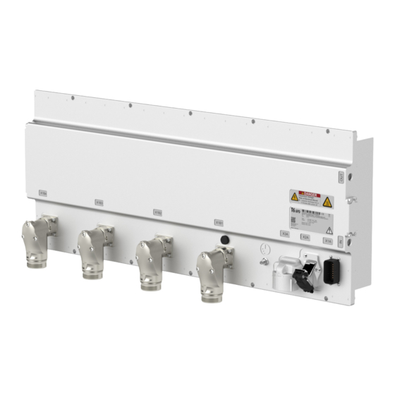
Page 30: Unintended Use
Central ground connection, connection for protective earth, => „4.3.1.2 Protective earth“. Pressure compensation valve for the housing Connector for control signals, LV-DC input (electrical system), HVIL, CAN and KEB diagnosis Ethernet interface RJ45 HV-DC input X1B1...X1B6 Motor output, number according to installed inverter modules (max. 6) -
Page 31: Nameplate
DC 565V max. 120A ⑦ Output AC 3 Ph 0...Uindc/√2 ⑩ 0...599Hz IP67 / IP6K9K ⑧ Modul X1B1: 16.5A KEB Automation KG ⑨ 32683 Barntrup www.keb.de Made in Germany Legend Barcode with serial number Test mark (CE or E1) Serial number, order number; Year and week of manufacture; Factory Material number, basic unit (=>... -
Page 32: Configurable Options
PRODUCT DESCRIPTION 2.6 Configurable options The following section describes the possibilities of the configurable options: features feature values Description Approval ATCE, ATE1 CE or E1 acceptance Basic unit 00T6A0x-xxxx Material number Basic unit (hardware) CBAA System configuration modules A, B, C MCU Firmware SWMxxx MCU Firmware MCU Runtime RTxxx CODESYS Runtime licence APP Utility BAxxx Application software - APP Utility: With e.g. -
Page 33: Type Code
B: 496 mm C: 649 mm System length D: 796 mm E: 946 mm F: 1096 mm Reserved 0: Default value Control type A: KEB default Series T6: COMBIVERT T6APD System 00: System 0 (default) Table 3: Type code The type code is not used as order code, but only for identification! -
Page 34: Technical Data
OPERATING CONDITIONS 3 Technical Data 3.1 Operating conditions 3.1.1 Evironmental conditions Storage Standard Class Notes Environmental conditions ISO 16750-4 Code A -40…85 °C Storage height – – Max. 3000 m above sea level Transport Standard Class Notes Environmental conditions ISO 16750-4 Code A -40…85 °C Operation... -
Page 35: Electrical Operating Conditions
OPERATING CONDITIONS 3.1.3 Electrical operating conditions 3.1.3.1 Device classification Requirement Standard Class Notes System voltage 300 V – – Overvoltage category – DIN EN 61800-5-1 Pulse voltage 2.5 kV Basic Basic insulation between HV-DC / DIN EN 60664-1 insulation AC and PE / housing DC test voltage 2260 V (60 s) ISO 6469-3... -
Page 36: Electromagnetic Compatibility
OPERATING CONDITIONS 3.1.3.2 Electromagnetic compatibility EMC emitted interference Standard Class Notes – DIN EN 61800-3 Line-conducted interferences ECE R10:Rev.5 – – Vo 2015/208 Radiated emissions DIN EN 61800-3 – 62-52 dB (μV/m) 30…75 MHz ECE R10:Rev.5 Radiated broadband interferences – 52-63 dB (μV/m) 75…400 MHz Vo 2015/208 63 dB (μV/m) 400 MHz…1 GHz 52-42 dB (μV/m) 30…75 MHz ECE R10:Rev.5 Radiated narrow band interfer-... -
Page 37: System And Module Data
SYSTEM AND MODULE DATA 3.2 System and module data 3.2.1 System weight System weight information => „2.1.1 System architecture“. 3.2.2 Electrical system data Electrical system data DC input voltage range 520…750 in_HV_dc Limited operation 1 200…520 HV1_dc Limited operation 2 750…820 HV2_dc DC rated input voltage... -
Page 38: Operation At The Aic (Active Infeed Controller)
+ to earth and DC link - to earth may occur. This is shown as example in „Figure 4: AIC filtering“. When operating on an AIC, KEB must be consulted. with 7.2 % Uk choke NOTICE Operation of the COMBIVERT T6APD on an AIC (Active Infeed Controller) ► Consultation with KEB. -
Page 39: Electrical Data High Voltage Interlock Loop (Hvil)
SYSTEM AND MODULE DATA 3.2.3 Electrical data High Voltage Interlock Loop (HVIL) The HVIL is designed as short-circuit bridge in the T6 system. There is no evalua- tion of the signal loop. Evaluation and reaction is to implement by the customer. For an overview of the connection =>... -
Page 40: Inverter Modules A, B, C
Rated operation corresponds to U = 400 V; f = 50 Hz (typical value). The technical data are for 2/4-pole standard motors. With other pole numbers the inverter must be dimensioned onto the rated motor current. Contact KEB for special or medium frequency motors. -
Page 41: Overload Characteristic (Ol)
SYSTEM AND MODULE DATA 3.2.5.1 Overload characteristic (OL) All drive inverters can be operated for 60 s at rated switching frequency with an utilization according to the data from „Table 13: Electrical data of the inverter modules“ Restrictions: • The thermal design of the heat sink is based on the rated output current and the maximum surrounding temperature. -
Page 42: Frequency-Dependent Maximum Current (Ol2)
SYSTEM AND MODULE DATA Operation in the range of the thermal overload limit Due to the high steepness of the overload characteristic, the duration of a permissible overload in this range cannot be determined exactly. Therefore, the design of the drive inverter should be assumed to have a maximum overload time of 300s. -
Page 43: Table 14: Frequency-Dependent Maximum Current For Module A
SYSTEM AND MODULE DATA The values for the respective module are listed in the following tables. Module Output frequency / Hz 12,5 8 kHz Frequency-dependent maximum current 16 kHz Table 14: Frequency-dependent maximum current for module A Module Output frequency / Hz 12,5 8 kHz... -
Page 44: Switching Frequency And Temperature
SYSTEM AND MODULE DATA 3.2.6 Switching frequency and temperature The drive inverter cooling is designed by way that the heat sink overtemperature thresh- old is not exceeded at rated conditions. A switching frequency higher than the rated switching frequency also produces higher losses and thus a higher heat sink heating. If the heat sink temperature reaches a critical threshold (T ) the switching frequency can be reduced automatically, in order to prevent that the drive inverter switches off... -
Page 45: Table 18: Technical Data Coolant
SYSTEM AND MODULE DATA Observe coolant flow rate ► Fall below => no sufficient cooling. ► Exceeding => heat sink is washed out. Coolant connection Coolant Water-glycol (45:55) The amount of coolant is Amount of coolant in the device depending on the system length Minimum amount of coolant (system length A) 0.125 l Maximum amount of coolant (system length F) 0.410 l... -
Page 46: Pressure Drops
SYSTEM AND MODULE DATA 3.2.7.1 Pressure drops Typical pressure drop at 30°C Legend 0,50 0,45 System length A 0,40 0,35 0,30 System length B 0,25 0,20 0,15 System length C 0,10 0,05 0,00 System length D l/min Typical pressure drop at 45°C 0,50 System length E 0,45... -
Page 47: Materials In The Cooling Circuit
SYSTEM AND MODULE DATA 3.2.7.2 Materials in the cooling circuit Avoid contact corrosion and pitting For the screw connections and also for the metallic articles in the cooling circuit which are in contact with the coolant (electrolyte) a material is to be selected, which forms a small voltage difference to the heat sink in order to avoid contact corrosion and/or pitting corrosion (electro-chemical voltage series, see the following table). The specific case of application must be checked by the customer in tuning of the complete cooling circuit... -
Page 48: Requirements For The Coolant
SYSTEM AND MODULE DATA 3.2.8 Requirements for the coolant General requirements for the coolant: The VGB cooling water directive (VGB R 455 P) contains in- formation on common cooling process techniques. Particu- Cooling water directive lary the interactions between cooling water and components of the cooling system are described. -
Page 49: Mechanical Data
MECHANICAL DATA 3.3 Mechanical data 3.3.1 Dimensions system length A 104,5 Ø8,5 Module Dimension in mm Weight in kg A / B X: 310 Y: 125 Z: M23 x 1.5 => „2.1.1 System architec- ture“ X: 348 Y: 151 Z: M40 x 1.5 Figure 9: Dimensions system length A... -
Page 50: Dimensions System Length B
MECHANICAL DATA 3.3.2 Dimensions system length b 104,5 Ø8,5 Module Dimension in mm Weight in kg A / B X: 310 Y: 125 Z: M23 x 1.5 => „2.1.1 System archi- tecture“ X: 348 Y: 151 Z: M40 x 1.5 Figure 10: Dimensions system length B... -
Page 51: Dimensions System Length C
MECHANICAL DATA 3.3.3 Dimensions system length C 104,5 Ø 8,5 Module Dimension in mm Weight in kg A / B X: 310 Y: 125 Z: M23 x 1.5 => „2.1.1 System architec- ture“ X: 348 Y: 151 Z: M40 x 1.5 Figure 11: Dimensions system length C... -
Page 52: Dimensions System Length D
MECHANICAL DATA 3.3.4 Dimensions system length D 104,5 Ø8,5 Module Dimension in mm Weight in kg A / B X: 310 Y: 125 Z: M23 x 1.5 => „2.1.1 System architecture“ X: 348 Y: 151 Z: M40 x 1.5 Figure 12: Dimensions system length D... -
Page 53: Dimensions System Length E
MECHANICAL DATA 3.3.5 Dimensions system length E 104,5 Ø8,5 Module Dimension in mm Weight in kg A / B X: 310 Y: 125 Z: M23 x 1.5 => „2.1.1 System architecture“ X: 348 Y: 151 Z: M40 x 1.5 Figure 13: Dimensions system length E... -
Page 54: Dimensions System Length F
MECHANICAL DATA 3.3.6 Dimensions system length f 1096 104,5 1054 1080 Ø8,5 Module Dimension in mm Weight in kg A / B X: 310 Y: 125 Z: M23 x 1.5 => „2.1.1 System archi- tecture“ X: 348 Y: 151 Z: M40 x 1.5 Figure 14: Dimensions system length F... -
Page 55: Connection To The Coolant For All Housing Sizes
MECHANICAL DATA 3.3.7 Connection to the coolant for all housing sizes NOTICE Damage to the threads A pairing of G1/4 internal thread and a conical/tapered external thread is not permitted. Name Version Coolant inlet G1/4 Coolant outlet G1/4 Figure 15: Connection to the coolant It is recommended to connect the G1/4 internal thread together with a G1/4 exter- nal thread. It is necessary to seal the fitting via the external threading. A suitable... -
Page 56: Installation And Connection
INSTALLATION AND CONNECTION 4 Installation and Connection 4.1 Mounting • Use screws M8 stainless steel A4 80 . Tightening torque 22 Nm DIN EN ISO 4762 ± 1.1 Nm. • It is recommended to use a medium screw locking varnish for threaded connections which corresponds to the ambient conditions. -
Page 57: Durchsteckmontage
INSTALLATION AND CONNECTION 4.1.1 Durchsteckmontage • It must be worked with a spacer that fits into the recess of the housing cover and bridges the M4 screw head height of min. 4 mm. • Only the specified fastening materials may be used, => „4.1 Mounting“. NOTICE Damage to the housing cover ► Clamping against the housing cover is not permitted. ► Clamping on the M4 screw heads is not permitted for push-through mounting. -
Page 58: Permissible Installation Position
INSTALLATION AND CONNECTION 4.2 Permissible installation position The following figure shows all permissible installation positions. Figure 18: Permissible installation position... -
Page 59: External Magnetic Fields
INSTALLATION AND CONNECTION 4.2.1 External magnetic fields Recommended restricted area Figure 19: External magnetic fields NOTICE faulty current measurements External magnetic fields can negatively influence the current measure- ment. Do not place or lay any • current-carrying wires • batteries • electric motors • switches • magnets in the marked recommended restricted area. -
Page 60: Connection Of The Power Unit
Fuses type aR; pay attention to the permissible voltage range !=> „3.2.2 Elec- trical system data“ HV-DC coupling (not included in the scope of delivery) KEB COMBIVERT T6 Figure 20: Connection at DC voltage supply The T6 must be pre-charged via a appropriate circuit. This is to be carried out, for example, passively with a minimum precharging resistance of 3 Ω... -
Page 61: High Voltage Interlock Loop (Hvil) - Exemplary Connection
CONNECTION Of THE POWER UNIT 4.3.1.1 High Voltage Interlock Loop (HVIL) - Exemplary connection The HVIL • is led as signal loop through all components of the HV system. • is a leading contact in the corresponding connectors (pilot contact). •... -
Page 62: Hv-Dc Supply X3A
CONNECTION Of THE POWER UNIT 4.3.1.3 HV-DC supply X3A NOTICE Short circuit due to reverse polarity when assembling the cables ! ► Observe the view of connector or coupling. ► Observe front or rear view. Parts data HV-DC supply X3A Connector manufacturer Rosenberger Website... -
Page 63: Coupling For Hv-Dc Supply
CONNECTION Of THE POWER UNIT 4.3.1.4 Coupling for HV-DC supply The following plug-in connection is not included in the scope of delivery. It is assembled by the vehicle manufacturer or directly ordered from the specified manufacturer. It is recommended to lay the HV-DC + and HV-DC - cables together. Only cables approved by the manufacturer must be used. -
Page 64: Motor Connection
CONNECTION Of THE POWER UNIT 4.3.2 Motor connection ➄ ➅ Legend KEB COMBIVERT T6 Motor connector (not included in the scope of delivery) Motor cable , place the shield on both sides and over a large surface to the functional earth... -
Page 65: Inverter Module A And B - Socket X1B
CONNECTION Of THE POWER UNIT 4.3.2.1 Inverter module A and B - socket X1B Parts data inverter module A and b - socket X1b Connector manufacturer Phoenix Contact Website www.phoenixcontact.com Name Device connector hybrid M23x1.5 Part No. Device connector 1621560 Part No. -
Page 66: Motor Connector For Inverter Module A And B
CONNECTION Of THE POWER UNIT 4.3.2.2 Motor connector for inverter module A and B The following plug-in connection is not included in the scope of delivery. It is assembled by the vehicle manufacturer or directly ordered from the specified connector manufac- turer. Manufacturer data accessories Connector manufacturer Phoenix Contact Website www.phoenixcontact.com Name Cable connector Hybrid M23x1.5 Number of poles... -
Page 67: Inverter Module C - Socket X1B
CONNECTION Of THE POWER UNIT 4.3.2.3 Inverter module C - socket X1B Parts data inverter module C - socket X1b Connector manufacturer Phoenix Contact Website www.phoenixcontact.com Name Device connector M40x1.5 hybrid Part No. Device connector 1623365 Part No. Crimp contact motor connection 1623380 Part No. -
Page 68: Motor Connector For Inverter Module C
CONNECTION Of THE POWER UNIT 4.3.2.4 Motor connector for inverter module C The following plug-in connection is not included in the scope of delivery. It is assembled by the vehicle manufacturer or directly ordered from the specified connector manufac- turer. Manufacturer data accessories Connector manufacturer Phoenix Contact Website www.phoenixcontact.com Cable connector M40x1,5-Hy- Name brid Number of poles... -
Page 69: Motor Cable Length
CONNECTION Of THE POWER UNIT 4.3.2.5 Motor cable length The maximum permissible resulting motor cable length per inverter module is 30 m. Longer cables, standard cables with a larger capacitive coating against shield / PE and cables with much bigger cross-section than required can: •... -
Page 70: Connection Of A Kty Sensor
CONNECTION Of THE POWER UNIT NOTICE Disturbances via temperature sensor connection ► Cables for temperature monitoring within the motor cable is only permissible with double shielding ! 4.3.3.1 Connection of a KTY sensor Sensor Resistance in kΩ Temperature in °C 0,498 KTY84/130 1,722... -
Page 71: Connection Of The Temperature Input In Operating Mode Ptc
CONNECTION Of THE POWER UNIT NOTICE Störungen durch fehlmessungen PT1000 sensors may not be combined with other detections. Other- wise, incorrect measurements would be the result. 4.3.3.3 Connection of the temperature input in operating mode PTC Operating mode Resistance in kΩ Temperature / state <... -
Page 72: Connection Of The Control
CONNECTION Of THE CONTROL 4.4 Connection of the control The following information must be observed when connecting: NOTICE Interference due to inductive and capacitive coupling ► Lay control and power cable separately (about 10…20 cm distance); Lay crossings in a right angle. ►... -
Page 73: Figure 33: Assignment Of The Terminal Block X1A
CAN_L_1 CAN-Low Port 1 (CAN 2.0) Release of the inverter modules – modulation permissible (KL15 – Switched plus from ignition starter switch) reserved reserved reserved KEB Service interface reserved reserved reserved Input High Voltage Interlock HVIL_IN => „4.3.1.1 High Voltage Interlock Loop (HVIL) - Exemplary connection“... -
Page 74: Terminal 15 „Enable
CONNECTION Of THE CONTROL 4.4.1.1 Terminal 15 „Enable“ Terminal 15 "Enable" is used for modulation release of the COMBIVERT T6 , i.e. the connected inverter modules can start the operation. X1A.9 Reference X1A.2 (LV_GND) potential Status 0 Status 1 Digital inputs / mA / mA _low... -
Page 75: Connection Example 1 - Connection Of The Can Client At T6
CONNECTION Of THE CONTROL 4.4.1.3 Connection example 1 - Connection of the CAN client at T6 ➀ Control connector X1A CAN_H_0 CAN_H_0 120 Ω ➂ CAN_H_0_R CAN_L_0 CAN_L_0 ➃ ➁ CAN_H_1 120 Ω CAN_H_1_R ➅ CAN_L_1 CAN_L_1 ➄ Client n Legend CAN bus 0 to client n-1 CAN bus 0 to client n+1... -
Page 76: Connection Example 2 - Assignment Of Both Can Interfaces With T6
CONNECTION Of THE CONTROL 4.4.1.4 Connection example 2 - Assignment of both CAN interfaces with T6 at the end of the respective ➀ Control connector X1A CAN_H_0 CAN_H_0 120 Ω CAN_H_0_R ➂ CAN_L_0 CAN_L_0 CAN_H_1 120 Ω CAN_H_1_R ➂ CAN_L_1 CAN_L_1 ➁... -
Page 77: Connection Plug For X1A
CONNECTION Of THE CONTROL 4.4.2 Connection plug for X1A The following plug-in connection is not included in the scope of delivery. It is assembled by the vehicle manufacturer. Manufacturer data accessories Connector manu- TE connectivity facturer Internet www.te.com Name AMP SEAL PLUG socket Part No. -
Page 78: Bus Interface X2A
CONNECTION Of THE CONTROL 4.4.3 bus interface X2A NOTICE Defect if not observed ! • The bus interface is not part of the E1 or CE acceptance tests and is not tested. • May not be connected during operation, is only designed as service interface. -
Page 79: Assignment Of The Ethernet Interface X2A
CONNECTION Of THE CONTROL 4.4.3.1 Assignment of the Ethernet interface X2A RJ45 without supply voltage (view with Auto-Cross Over) reserved reserved reserved reserved Table 28: PIN description RJ45 Ethernet The IP address for parameterization via the control is 192.168.0.100 Subnet mask 255.255.255.0... -
Page 80: Certification
CERTIfICATION 5 Certification ECE R10-/CE certification Depending on the logo on the nameplate, the device is either ECE R10 or CE certified. 5.1 ECE R10 The COMBIVERT T6 system has been approved as electrical / electronic sub-as- sembly in accordance with ECE Regulation No. 10 including Amendment No. 05 Sup- plement 01 The intended use is the installation in vehicles for the control and regulating of three-phase motors. -
Page 81: Manufacturer´s Declaration
A. W. Hovestadt / Conformance Officer W. Wiele / Technical Manager This declaration of conformity is issued under the sole responsibility of KEB. This declaration certifies the conformity with the named directives, but does not contain any assurance of quality. - Page 82 Base for the complete approval is the definition of a complete PDS ( power drive system ). For not exceeding the required limits or minimum levels of immunity it is necessary to use the KEB internal filters and observe the given wiring specifications.
-
Page 83: Figure 40: Declaration Of Conformity
A. W. Hovestadt / Conformance Officer W. Wiele / Technical Manager This declaration of conformity is issued under the sole responsibility of KEB. This declaration certifies the conformity with the named directives, but does not contain any assurance of quality. -
Page 84: Revision History
REVISION HISTORY 6 Revision History Version Date Description 2018-05 Pre-series Pre-series, adaptation of the standards list, symbols, nameplate and the table power 2018-10 input LV-DC 2018-11 Pre-series, addition of safety instructions, extension of the table pressure drops 2019-01 Pre-series, editorial changes Conversion to series version, E1 specific descriptions; change product description;... - Page 85 Tel: +33 149620101 Fax: +33 145767495 c / Mitjer, Nave 8 - Pol. Ind. LA MASIA E-Mail: info@keb.fr Internet: www.keb.fr 08798 Sant Cugat Sesgarrigues (Barcelona) Spain Tel: +34 93 8970268 Fax: +34 93 8992035 E-Mail: vb.espana@keb.de Germany Geared Motors KEB Antriebstechnik GmbH...
- Page 86 Automation with Drive www.keb.de KEB Automation KG Suedstrasse 38 32683 Barntrup Tel. +49 5263 401-0 E-Mail: info@keb.de...
Need help?
Do you have a question about the COMBIVERT T6APD and is the answer not in the manual?
Questions and answers