KEB Combivert F5 Instruction Manual
Ttl voltage supply 15/24v
incremental encoder
Hide thumbs
Also See for Combivert F5:
- Applications manual (378 pages) ,
- Reference manual (349 pages) ,
- Instruction manual (196 pages)

Related Manuals for KEB Combivert F5


Summary of Contents for KEB Combivert F5
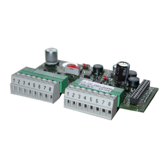
- Page 1 COMBIVERT INSTRUCTION MANUAL Incremental encoder Channel 1 TTL Voltage Supply 15/24V Mat.No. Rev. DKF5ZEM-K030...
-
Page 3: Table Of Contents
Inhaltsverzeichnis 1. Safety Instructions ..................Validity ........................4 1.2 Qualification ......................4 2. Product description ..................General .......................5 Part number ......................5 Scope of delivery (option or replacement delivery) ..........5 Mechanical installation ..................6 3. Description of the Interface ................Power supply ......................6 3.1.1 Adjustment of the Supply Voltage ..............7 Channel 1 ......................7 3.2.1... -
Page 4: Safety Instructions
The used semiconductors and components of KEB are developed and dimensi- oned for the use in industrial products. If the KEB COMBIVERT is used in ma- Use under spe-... -
Page 5: Product Description
Incremental encoder input TTL 15/24V General Each of the interface cards delivered by KEB include two interfaces. As there are numerous different combinations available each interface will be described by means of separate instructions. The instruction covers the installation of the interface card, the connection as well as the start-up of a suitable encoder. -
Page 6: Mechanical Installation
Encoder Input TTL at Channel 1 - 15/24V voltage supply Mechanical installation All kind of works on the inverter may be carried out by authorized personnel in accordance with the EMC and safety rules only. • Switch inverter de-energized and await capacitor discharge time •... -
Page 7: Adjustment Of The Supply Voltage
Encoder Input TTL at Channel 1 - 15/24V voltage supply 3.1.1 Adjustment of the Supply Voltage 15 V 24 V or external supply via the control Channel 1 3.2.1 Specification Terminal strip 8-pole Interface type Incremental encoder input Output signals 5 V TTL according to RS485 Outputs / tracks A, B and N with the respective inverted signals... -
Page 8: Signal Input
Encoder Input TTL at Channel 1 - 15/24V voltage supply 3.3.3. Signal input 3.3.3.1 Input signals of encoder inputs At the encoder interface TTL input the signals A+ and B+ are electrically phase-shifted by 90° rectangular signals with the respective inverted signals. Figure 3.3.3.1 Signal tracks A and B with inverse signals 2...5 V... -
Page 9: Encoder Breakage Recognition
Encoder Input TTL at Channel 1 - 15/24V voltage supply 3.2.3.3 Encoder breakage recognition For a monitoring of the encoder to channel 1 and the encoder cable the signal tracks and the zero track are monitored. If the connected encoder has no zero track, then the the 5 V- supply must be assigned to track N+ and COM to N- at the encoder plug. -
Page 10: Encoder Channel
U : see encoder description KEB encoder cable resistance R: 0,036 Ω/m at 0,5 mm² 3.2.7 Tested encoder The following TTL incremental encoders have been tested by KEB on it application: Heidenhain ROD 426 However, this does not restrict the use of rotary encoder with same specifications of other manufacturers. Channel 2 The description of input X3B is depending on the used encoder interface. -
Page 11: Start-Up
Encoder Input TTL at Channel 1 - 15/24V voltage supply Start-up After the installation or exchange of an encoder interface some adjustments of the inverter/ servo software have to be done before operation: • Switch on inverter • Select application mode • Select parameter Ec.0 and control whether value „13 incremental encoder input 24V TTL In“ is entered.The displayed value has to be confirmed by „ENTER“ in any case. • Select Ec.1 and adjust increments per revolution • Select Ec.42 (Ec.20 upto V2.8) and adjust the encoder breakage recognition dependent on the case of operation. • If several slaves are connected, deactivate the terminating resistor with Ec.20 Bit 1 (do not switch off at last slave). - Page 12 +39 02 3353531 • fax: +39 02 33500790 net: www.keb.de • mail: kebitalia@keb.it KEB Power Transmission Technology (Shanghai) Co.,Ltd. No. 435 Qianpu Road, Chedun Town, Songjiang District, KEB Japan Ltd. CHN-Shanghai 201611, P.R. China 15–16, 2–Chome, Takanawa Minato-ku fon: +86 21 37746688 • fax: +86 21 37746600...
Need help?
Do you have a question about the Combivert F5 and is the answer not in the manual?
Questions and answers