
Related Manuals for KEB combivert B6


Summary of Contents for KEB combivert B6
- Page 1 C O M B I V E R T Installation Manual Housing B 1.5…2.2 kW 230 V 2.2…4.0 kW 400 V The general EMC and safety directions at www.keb.de have to be observed ! Mat.No. Rev. Part 00B60EMKB00...
- Page 3 GB - 3...
- Page 4 This manual describes the KEB COMBIVERT B6. Particular attention is paid to the in- stallation, the connection as well as the basic operation. Due to the various application and programming possibilities, the application-specific connection and/or wiring diagram, the parameter adjustment as well as instructions to the start-up are to be taken from the documentation of the machine manufacturer.
-
Page 5: Table Of Contents
Table of Contents Safety and Operating Instruc- Annex A ..........35 tions ..........6 A.1 Overload characteristic ....35 A.2 Calculation of the motor voltage ..35 Product description .....7 A.3 Maintenance ........35 Intended use ........7 A.4 Storage ........36 Unit identification ......7 A.5 Activation of the temperature input Technical data ........8 (only housing B) ......37 2.3.1 230 V class .......... -
Page 6: Safety And Operating Instructions
Important, absolutely read Safety and Operating Instructions Safety and Operating Instructions for drive converters (in conformity with the Low-Voltage Directive 2006/95/EC) 1. General Drive converters contain electrostatic sensitive components which are liable to damage through improper use. Electric In operation, drive converters, depending on their degree of components must not be mechanically damaged or destroyed protection, may have live, uninsulated, and possibly also moving (potential health risks). -
Page 7: Product Description
Product description Product description Intended use The frequency inverter KEB COMBIVERT B6 serves exclusively for the control and regulation of asynchronous motors. The operation of other electric consumers is prohibited and can lead to the destruction of the unit. Frequency inverter are components which are intended for the installation in electric sy- stems or machines. -
Page 8: Technical Data
Product description Technical data 2.3.1 230 V class Inverter size Housing size Phases Output rated power [kVA] Max. rated motor power [kW] Output rated current Max. short time current 12.6 OC-tripping current 15.1 Input rated current [A ] Max. permissible mains fuse (inert) Rated switching frequency [kHz] Max. -
Page 9: 400 V Class
Product description 2.3.2 400 V class Inverter size Housing size Phases Output rated power [kVA] Max. rated motor power [kW] Output rated current Max. short time current 10.4 OC-tripping current 12.5 Input rated current Max. permissible mains fuse (inert) Rated switching frequency [kHz] Max. -
Page 10: Dimensions And Terminals
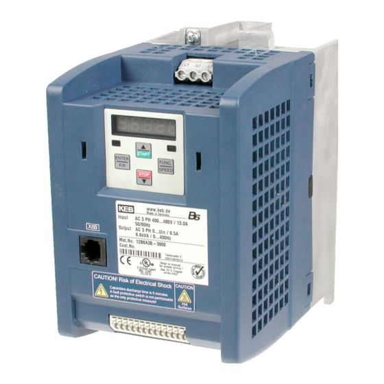
Product description Dimensions and Terminals 58,5 Connection for mains supply Connection for motor, braking resistor and temperature detection Connection for control lines HSP5 Interface for parametrizing. Used accessories for PC connection: • Adapter SUB-D9 to RJ45 (mat.no. 00F50C0-0020) • RS232/HSP5 converter (mat.no. 00F50C0-0010) Connection protective conductor GB - 10... -
Page 11: Installation And Connection
- ideal in a metal cable duct. • Mount COMBIVERT well conducting with the mounting plate. Remove the paint beforehand. You can find further instructions regarding the EMC- conform wiring in the Internet at KEB. GB - 11... -
Page 12: Connection Of Power Circuit
Connection of power circuit 3.3.1 Wiring instructions Absolutely observe the connecting voltage of the KEB COMBIVERT. A 230V- unit will be immediately destructed on a 400V-power supply. Never exchange the mains and motor cables. Some countries demand that the PE-terminal is directly connected to the terminal box (not over the mounting plate). -
Page 13: Dc Connection
Installation and Connection 3.3.3 DC connection DC connection Input voltage 230 V-class: 250…370 V DC Input voltage 400 V-class: 420…720 V DC – – – – Terminal strip X1B Tightening torque 0.6 Nm (5 lb inch) Connection cross-section 1.5…4 mm² (AWG 16-11) At DC supply pay attention to the permissible voltage range of the fuses ! 3.3.4 Motor connection... -
Page 14: Wiring Example Braking Resistor
T1/T2 is activated as described in annex A.5. Main fuses Push-bottom switch for switch on Line contactor with auxiliary contacts Emergency-off switch KEB COMBIVERT B6 Braking resistor with temperature monitoring 3.3.6 Note to the function In the example above the locking of the line contactor K1 is interrupted in case of overhe- ating of the braking resistor. -
Page 15: Control Board Xxb6Axx-Xxx (Default)
Installation and Connection Control board xxB6Axx-xxx (default) 3.4.1 X2A Control terminal strip The control connections are „safety separated circuits“ according to PELV requi- rements. • Conductor cross-section AWG 20-16 rigidly or flexibly 0.5…1.5 mm² Wire-end ferrule without plastic case 0.5…1 mm² Wire-end ferrule with plastic case 0.5 mm²... -
Page 16: Connection Of The Control Terminal Strip
Installation and Connection 3.4.2 Connection of the control terminal strip 0-10VDC Current signal max. 10mA 0…20 mA 4…20 mA 0-10VDC Setpoint Dropping potentiometer resistor R2 2.5 kΩ 1.15 kΩ 3 kΩ 1.3 kΩ 5 kΩ 2.1 kΩ 10 kΩ 3.7 kΩ 15 V ±8 % max. -
Page 17: Control Board Xxb6Bxx-Xxx (Can)
Installation and Connection Control board xxB6Bxx-xxx (CAN) 3.5.1 X2A Control terminal strip The control connections are „safety separated circuits“ according to PELV requi- rements. • Conductor cross-section AWG 20-16 rigidly or flexibly 0.5…1.5 mm² Wire-end ferrule without plastic case 0.5…1 mm² Wire-end ferrule with plastic case 0.5 mm²... -
Page 18: Connection Of The Control Terminal Strip
Installation and Connection 3.5.2 Connection of the control terminal strip CAN high CAN low CAN high CAN low 15 V ±10 % max. 50 mA max. 30 V DC / 0.01…1 A To avoid interferences separate shieldings must be provided for bus and control lines. Depending on the use of the relay output, an extra shielding is to be used, too. -
Page 19: Operation Of The Unit
Double function keyboard Keyboard operation 4.2.1 Parameter numbers and values When switching on KEB COMBIVERT B6 the value of parameter CP.1 appears. The function key changes between the parameter value and parameter number. With UP (▲) and DOWN (▼) the parameter number or at changeable parameters the value is increased/ decreased. -
Page 20: Password Input Cp.0
Operation of the Unit 4.2.3 Password input CP.0 The KEB COMBIVERT is outfitted with an extensive password protection. Dependent on the entered password the following modes are possible: Display Mode Password CP_ro End customer menu (CP-Parameter) read-only CP_on End customer menu (CP-Parameter) read/write... -
Page 21: Drive Mode
4.2.4 Drive mode The Drive Mode is an operating mode of KEB COMBIVERT that permits the manual starting of the drive by the keyboard. After switching the control release the set value and rotation setting are effected exclusively over the keyboard. In order to activate the drive mode the corresponding password (see 4.2.3) must be entered in CP. -
Page 22: Parameter Description
CP-Parameter Parameter Description Resolu- CP-Parameter Setting Range Default Unit Based ↵ tion CP.00 Password input 0…9999 – – – ud.01 CP.01 Actual frequency display -400…400 0.0125 – ru.03 CP.02 Set frequency display -400…400 0.0125 – ru.01 CP.03 Inverter status 0…255 –... - Page 23 „Reverse Constant“; drive runs with constant speed and direction of rotation reverse. Status messages and information about the cause and removal are to be found in www. keb.de > Service&Downloads > Downloads ==> status_gb.pdf. CP.17 Voltage stabilization With this parameter a regulated output voltage in relation to the rated frequency can be adjusted.
- Page 24 CP-Parameter CP.25 Max. constant current This function protects the frequency inverter against switch off through overcurrent during constant output frequency. When exceeding the adjusted value, the output frequency is reduced until the value drops below the adjusted value. CP. 03 displays "SSL" at active function.
- Page 25 CP-Parameter CP.27 Response Description Quick stopping, Fast stop - switch off of the modulation after reaching modulation off, 0 Hz. Correct the error for the restart and activate restart after reset reset. The drive remains in condition fast stop until a Status message A.xx reset signal is recognized.
- Page 26 CP.30 Analog output 1 / function CP.30 defines the function of analog output 1. The output at the analog output is always made in a range of 0…+10 V. Negative values are inverted and the output is displayed in a positive value. Value Function Scaling factor 0…100 % (0…±100 %)
- Page 27 Value Function Real direction of rotation = set direction of rotation Utilization (CP.6) > switching level Active current > switching level Intermediate circuit voltage (CP.7) > switching level Real value (CP.1) > switching level Set value (CP.2) > switching level Absolute set value at AN1 >...
-
Page 28: Error And Status Display
Error and Status Display Error and Status Display At KEB COMBIVERT error messages are always represented with an "E." and the appropri- ate error in the display. Error messages cause the immediate deactivation of the modulation. Restart possible only after reset or autoreset. - Page 29 Error and Status Display Display COMBIVIS display dec hex Meaning rAcc reverse acceleration 43 Acceleration with the adjusted ramps in counterclo- ckwise direction of rotation (reverse). rcon reverse constant 45 Acceleration / deceleration phase is completed and it is driven with constant speed / frequency in counter- clockwise direction of rotation (reverse).
- Page 30 Error and Status Display Display COMBIVIS display dec hex Meaning E.dri Error ! driver relay 33 Error: Driver relay. Relay for driver voltage on power circuit has not picked up even though control release was given. E.EEP Error ! EEPROM 15 After reset the operation is again possible (without defective t storage in the EEPROM)
- Page 31 Error and Status Display Display COMBIVIS display dec hex Meaning E. OC Error ! overcurrent Occurs, if the specified peak current is exceeded. Short cicuit at the output Ground fault motor cable too long Phase error The load is too big at turned off constant current limit.
- Page 32 Error and Status Display Display COMBIVIS display dec hex Meaning E.OL2 Error ! overload 2 13 The standstill constant current has been exceeded (see technical data and overload characteristics). The error can only be reset if the cooling time has elapsed and the message E.nOL2 is displayed.
- Page 33 Error and Status Display Display COMBIVIS display dec hex Meaning E. UP Error ! underpotential Occurs, if the DC-link voltage falls below the per- missible value. Voltage losses through wrong cabling. inverter rating too small A digital input was programmed as external error input with error message E.UP has released.
- Page 34 Error and Status Display Display COMBIVIS display dec hex Meaning A.OHI Warning ! overheat 57 The temperature in the interior of the inverter lies internal above the permissible level. The switch off time was started. The programmed response to this warning message is executed.
-
Page 35: Annex A
Annex A Annex A Overload characteristic Release time [s] Load [%] On exceeding a load of 105% the overload integrator starts. When falling below the inte- grator counts backwards. If the integrator achieves the overload characteristic, the error E.OL is triggered. Calculation of the motor voltage The motor voltage for dimensioning of the drive is depending on the used components. -
Page 36: Storage
If the capacitor starts running with rated voltage, it is tried to build the oxide film abrupt again. This causes heat and gas and leads to the destruction of the capacitor. In order to avoid defectives, the KEB COMBIVERT must be started up depending on the storage period in accordance with the following specification: Storage period <... -
Page 37: Activation Of The Temperature Input (Only Housing B)
Input voltages as before, however double the times per year. Eventually change capacitors. After expiration of this start-up the KEB COMBIVERT can be operated on nominal rating conditions or delivered to a new storage. Activation of the temperature input (only housing B) The parameter Pn.12 determines the response of the drive when terminals T1, T2 of terminal... - Page 38 Annex A FUNC. FUNC. SPEED SPEED STOP START FUNC. SPEED ENTER ENTER FUNC. SPEED ENTER START FUNC. SPEED START START ENTER ENTER FUNC. SPEED START Example to set Pn.12 in application mode GB - 38...
-
Page 39: Annex B
In this case the operator may need to take corresponding measures. UL marking Acceptance according to UL is marked at KEB inverters with the adjacent logo on the type plate. To be conform according to UL for the use on the North American Market the following instructions must be observed (original text in accordance with UL): •... - Page 40 Annex B • Branch Circuit Protection Information about the required Branch Circuit Protection which need to be installed external to the product: see Table 1 For Type E combination motor controllers, the marking shall include the motor controller manufacturer, model number,rated voltage and rated hp: see Table 2 Cat.
-
Page 41: Additional Manuals
> Service&Downloads > Downloads General instructions • Part 1 EMC-and safety instructions Service notes • Up- /Download of parameter lists with KEB COMBIVERT • Error messages Instruction and information for construction and development • Application Manual • CAN manual •... - Page 42 GB - 42...
- Page 43 GB - 43...
- Page 44 +39 02 3353531 • fax: +39 02 33500790 net: www.keb.de • mail: kebitalia@keb.it KEB Power Transmission Technology (Shanghai) Co.,Ltd. No. 435 Qianpu Road, Chedun Town, Songjiang District, KEB Japan Ltd. Shanghai 201611, P.R. China 15–16, 2–Chome, Takanawa Minato-ku fon: +86 21 37746688 • fax: +86 21 37746600...
Need help?
Do you have a question about the combivert B6 and is the answer not in the manual?
Questions and answers