KEB COMBIVERT F5 Instruction Manual
Hide thumbs
Also See for COMBIVERT F5:
- Applications manual (378 pages) ,
- Reference manual (349 pages) ,
- Instruction manual (196 pages)

Related Manuals for KEB COMBIVERT F5


Summary of Contents for KEB COMBIVERT F5
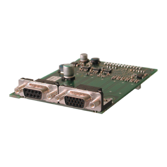
- Page 1 COMBIVERT INSTRUCTION MANUAL Encoder Interface Channel 1 variable Channel 2 Incremental Encoder TTL-Output 03/2008...
-
Page 3: Table Of Contents
Table of Contents 1. Safety Instructions ..................4 Validity ........................4 Qualification ......................4 2. Product Description ..................5 General .......................5 Material number ....................5 Scope of delivery (option or replacement delivery) ..........5 Mechanical installation ..................6 3. Description of the Interface ................6 Voltage supply ....................6 Channel 1 ......................6 Channel 2 ......................7... -
Page 4: Safety Instructions
The used semiconductors and components of KEB are developed and dimensio- ned for the use in industrial products. If the KEB COMBIVERT is used in machi- Use under spe-... -
Page 5: Product Description
General Each of the interface cards delivered by KEB include two interfaces. As there are numerous different combinations available each interface will be described by means of separate instructions. The instruction covers the installation of the interface card, the connection as well as the start-up of a suitable encoder. -
Page 6: Mechanical Installation
Incremental encoder output TTL on channel 2 Mechanical installation All kind of works on the inverter may be carried out by authorized personnel in accordance with the EMC and safety rules only. • Switch inverter de-energized and await capacitor discharge time •... -
Page 7: Channel 2
Incremental encoder output TTL on channel 2 Channel 2 3.3.1 Specifications Terminal strip 8-pole or socket SUB-D9 Interface type Incremental encoder output Output signals 5 V TTL according to RS485 Outputs / tracks A, B and N with the respective inverted signals Limiting frequency 300 kHz 1…16383 inc (recommendation 2500 inc for speed upto... -
Page 8: Output Of The Zero Signal
The zero signal has TTL level. 3.3.4 Connection of the incremental encoder simulation 3.3.4.1 Encoder cable KEB encoder cables are corresponding to the following specification: Signal lines 3 x (2 x 0,14 mm²) Supply lines 2 x 0,5 mm² Particularities... -
Page 9: Line Length
Incremental encoder output TTL on channel 2 3.3.4.2 Line length The maximum line length for the connection line is limited by the signal frequency, cable capacity and the line resistance. 3.3.4.3 Encoder cabel at SUB-D9 • Encoder cable double-shielded and twisted in pairs •... -
Page 10: Start-Up
Incremental encoder output TTL on channel 2 Start-up After the installation or exchange of an encoder interface some adjustments of the inverter/ servo software have to be done before operation: • Switch on inverter • Select application mode • Select parameter Ec.10 and control whether value „2: Incremental encoder output“ is entered. - Page 12 +49 5263 401-0 • fax: +49 5263 401-116 net: www.keb.de • mail: info@keb.de KEB Antriebstechnik GmbH & Co. KG KEB (UK) Ltd. Wildbacher Str. 5 • D–08289 Schneeberg 6 Chieftain Buisiness Park, Morris Close fon: +49 3772 67-0 • fax: +49 3772 67-281...
Need help?
Do you have a question about the COMBIVERT F5 and is the answer not in the manual?
Questions and answers