Sign In
Upload
Manuals
Brands
KEB Manuals
Media Converter
COMBIVERT T6APD
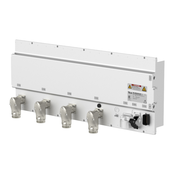
KEB COMBIVERT T6APD Manuals
Manuals and User Guides for KEB COMBIVERT T6APD. We have
1
KEB COMBIVERT T6APD manual available for free PDF download: Instructions For Use Manual
KEB COMBIVERT T6APD Instructions For Use Manual (86 pages)
Brand:
KEB
| Category:
Media Converter
| Size: 9 MB
Table of Contents
Preface
3
Signal Words and Symbols
3
More Symbols
3
Laws and Guidelines
4
Warranty and Liability
4
Support
4
Copyright
4
Table of Contents
5
List of Figures
8
List of Tables
9
Glossary
10
List of Standards
12
Basic Safety Instructions
15
Target Group
15
Transport, Storage and Proper Use
15
Installation
16
Electrical Connection
17
EMC-Compatible Installation
18
Voltage Test
18
Insulation Measurement
18
Requirements to the Entire System
18
Start-Up and Operation
19
Maintenance
21
Repair
21
Disposal
22
Product Description
23
T6 APD - Principle Construction
25
Figure 1: T6 APD - Principle Construction
25
System Architecture
26
Table 1: System Architecture
28
Specified Application
29
Residual Risks
29
Unintended Use
30
Overview of the Combivert T6APD
30
Figure 2: T6 APD - Complete Overview
30
Nameplate
31
Figure 3: Nameplate
31
Configurable Options
32
Table 2: Configurable Options
32
Type Code
33
Table 3: Type Code
33
Technical Data
34
Operating Conditions
34
Evironmental Conditions
34
Mechanical Environmental Conditions
34
Table 4: Evironmental Conditions
34
Table 5: Mechanical Environmental Conditions
34
Electrical Operating Conditions
35
Device Classification
35
Table 6: Device Classification
35
Electromagnetic Compatibility
36
Table 7: Electromagnetic Compatibility
36
System and Module Data
37
System Weight
37
Electrical System Data
37
Table 8: Electrical System Data
37
Operation at the AIC (Active Infeed Controller)
38
Figure 4: AIC with 7.2 % Uk Choke Filtering
38
Figure 5: AIC with Sine-Wave EMC Filter
38
Table 9: System Data
38
Electrical Data High Voltage Interlock Loop (HVIL)
39
Low Voltage LV-DC Input
39
Table 10: Electrical Data High Voltage Interlock Loop (HVIL)
39
Table 11: Electrical Data Low Voltage DC Input
39
Table 12: Power Input of the Modules
39
Inverter Modules A, B, C
40
Table 13: Electrical Data of the Inverter Modules
40
Overload Characteristic (OL)
41
Figure 6: Switch-Off Time T Depending on the Overload I/IN (OL) with the Example of Module a
41
Frequency-Dependent Maximum Current (OL2)
42
Figure 7: Typical Overload Characteristic in the Lower Output Frequencies (OL2) Example Module a
42
Table 14: Frequency-Dependent Maximum Current for Module a
43
Table 15: Frequency-Dependent Maximum Current for Module B
43
Table 16: Frequency-Dependent Maximum Current for Module C
43
Switching Frequency and Temperature
44
Cooling and Coolant Connection
44
Table 17: Switching Frequency and Temperature
44
Table 18: Technical Data Coolant
45
Pressure Drops
46
Figure 8: Typical Pressure Drops
46
Materials in the Cooling Circuit
47
Table 19: Electrochemical Series / Standard Potentials against Hydrogen
47
Requirements for the Coolant
48
Table 20: General Requirements for the Coolant
48
Mechanical Data
49
Dimensions System Length a
49
Figure 9: Dimensions System Length a
49
Dimensions System Length B
50
Figure 10: Dimensions System Length B
50
Dimensions System Length C
51
Figure 11: Dimensions System Length C
51
Dimensions System Length D
52
Figure 12: Dimensions System Length D
52
Dimensions System Length E
53
Figure 13: Dimensions System Length E
53
Dimensions System Length F
54
Figure 14: Dimensions System Length F
54
Connection to the Coolant for All Housing Sizes
55
Figure 15: Connection to the Coolant
55
Installation and Connection
56
Mounting
56
Figure 16: Mounting Holes
56
Durchsteckmontage
57
Figure 17: Push-Through Mounting
57
Permissible Installation Position
58
Figure 18: Permissible Installation Position
58
External Magnetic Fields
59
Figure 19: External Magnetic Fields
59
Connection of the Power Unit
60
High Voltage DC Supply
60
Figure 20: Connection at DC Voltage Supply
60
High Voltage Interlock Loop (HVIL) - Exemplary Connection
61
Protective Earth
61
Figure 21: Example of a HVIL Wiring
61
Figure 22: Protective Earth
61
HV-DC Supply X3A
62
Figure 23: HV-DC Supply X3A (Front View on the Device)
62
Coupling for HV-DC Supply
63
Figure 24: Coupling for HV-DC Supply (Counterpart for X3A)
63
Table 21: Plug-In Connector Coding
63
Motor Connection
64
Figure 25: Wiring between Motor and T6
64
Inverter Module a and B - Socket X1B
65
Figure 26: Socket Inverter Module a and B (Front View Socket)
65
Motor Connector for Inverter Module a and B
66
Figure 27: Coupling Motor Connector for Inverter Module a and B
66
Inverter Module C - Socket X1B
67
Figure 28: Socket Inverter Module C (Front View Socket)
67
Motor Connector for Inverter Module C
68
Figure 29: Coupling Motor Connector for Inverter Module C
68
Motor Cable Length
69
Interconnection of the Motor
69
Temperature Detection
69
Table 22: Possible Applications of Temperature Detection
69
Connection of a KTY Sensor
70
Connection of a PT1000 Sensor
70
Figure 30: Connection of a KTY Sensor
70
Figure 31: Connection of a PT1000 Sensor
70
Table 23: Specification of the Temperature Input
70
Table 24: Specification of the Temperature Input
70
Connection of the Temperature Input in Operating Mode PTC
71
Figure 32: Connecting Examples Temperature Input
71
Table 25: Specification of the Temperature Input
71
Connection of the Control
72
Assignment of the Connector X1A
72
Figure 33: Assignment of the Terminal Block X1A
73
Terminal 15 „Enable
74
Specification Of The Can Bus
74
Figure 34: Connection of the Input Terminal 15 „Enable
74
Table 26: Specifications of the Input „Enable
74
Table 27: Specifications of the CAN Bus
74
Connection Example 1 - Connection of the CAN Client at T6
75
Figure 35: Connection Example 1 of the CAN Clients at T6APD
75
Connection Example 2 - Assignment of both CAN Interfaces with T6
76
Apd
76
Of the Respective Bus
76
Figure 36: Connection Example 2 Assignment of both CAN Interfaces with T6APD
76
Connection Plug for X1A
77
Figure 37: Coupling for Control Connector X1A
77
Bus Interface X2A
78
Figure 38: Bus Interface X2A
78
Figure 39: Bus Interface X2A
78
Assignment of the Ethernet Interface X2A
79
Table 28: PIN Description RJ45 Ethernet
79
Certification
80
Ece R10
80
Table 29: Certification According to ECE Regulation No. 10 Including Amendment 05 Supple
80
Manufacturer´s Declaration
81
Figure 40: Declaration of Conformity
83
Revision History
84
Advertisement
Advertisement
Related Products
KEB combivert B6
KEB COMBIVERT 2M.F5.K8F-6009
KEB COMBIVERT F5 10F5C1B-2A0A
KEB COMBIVERT F5-AIC
KEB COMBIVERT F5
KEB COMBIVERT F5 Servo
KEB COMBIVERT S4
KEB COMBIVERT F0
KEB COMBIVERT F5 Series
KEB combiverty
KEB Categories
DC Drives
Controller
Control Unit
Inverter
Industrial Equipment
More KEB Manuals
Login
Sign In
OR
Sign in with Facebook
Sign in with Google
Upload manual
Upload from disk
Upload from URL