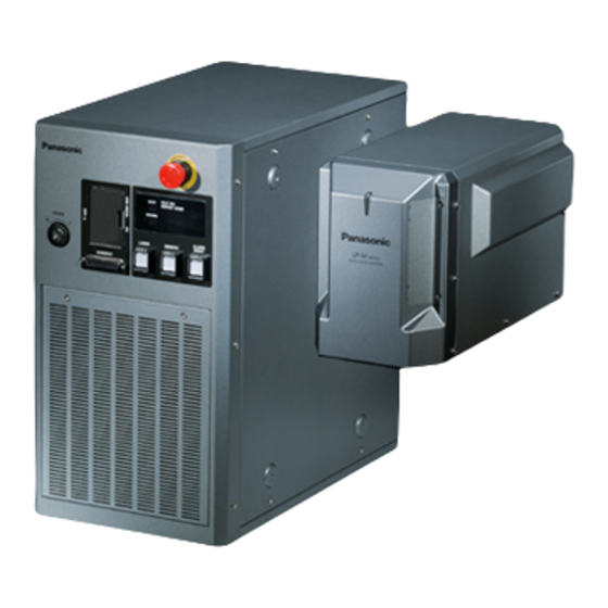
Panasonic LP-M Series Maintenance Manual
Laser marker
Hide thumbs
Also See for LP-M Series:
- Serial communication manual (205 pages) ,
- Operation manual (308 pages)
Table of Contents
Troubleshooting


Need help?
Do you have a question about the LP-M Series and is the answer not in the manual?
Questions and answers