Table of Contents
Troubleshooting

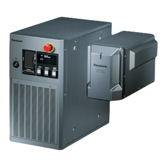
Related Manuals for Panasonic LP-M500-LS1


Summarization of Contents
Cautions in Handling
Hazard Symbols
Explains symbols for DANGER, WARNING, and CAUTION hazard levels.
Instruction Symbols
Explains symbols indicating prohibited, required, or careful procedures.
For the Proper Use of Product
Usage Environment
Specifies conditions for product use, including temperature, humidity, and cleanliness.
Installation and Mounting
Details on how to install and mount the laser marker head and controller units.
Order Recommendations and Considerations
Safety Precautions
General safety advice for electrical components, use environments, and redundancy design.
Acceptance Inspection
Procedure for performing an acceptance inspection of the product upon receipt.
Related Regulations and Standards
Applicable Regulations and Standards
Lists models and their compliance with EN, JIS, FDA, GB, and KC standards.
Implementing Safety Measures for Laser Products
Removing and Eliminating Dust or Gas
Procedures for safely removing and disposing of dust or gas generated during laser processing.
Attention for Laser Marker Disposal
Guidelines for proper disposal of the laser marker according to applicable laws.
How to Read this Document
Symbol Indications
Explains the meaning of 'Notice' and 'Reference' symbols used in the manual.
Type of Manuals
Lists and describes the various manuals available for the product.
Target Laser Marker Models
Model Name Description
Explains product series, output class, marking field, laser gate, and model suffixes.
Safety Use of Laser Product
Radiation Information
Details on laser class (4 and 2), wavelength, output, and hazard distances.
Safety Protection Measures for Users
Construction of Interlock System
Requirements for constructing protective enclosures and interlock systems for laser safety.
Wearing Protective Goggles
Mandatory use of specific laser protective goggles for operator eye protection.
Protective Enclosure
Guidelines for constructing enclosures to prevent accidental laser beam exposure.
Key Control
Importance of key management for unauthorized operation prevention.
Safety Measures
Power Failure Recovery
Procedure to implement a laser re-pumping system for safety during power failures.
Radiation Direction of Laser Beam
Measures for ensuring laser beam direction is visible and checked by others.
Termination of Laser Beam
Method for terminating the laser beam path within the marking range.
Protective Clothing
Requirement to wear flame-resistant clothing that minimizes skin exposure.
Safety Functions on Laser Marker
Internal Shutter
Shutter inside the head that stops laser beam emission by closing.
Laser Radiation Indicator
Indicator operations showing laser pumping and emitting status.
Key Switch
Used for system power ON/OFF to prevent unauthorized operation.
Emergency Stop Switch
Forcible stop of laser pumping and radiation.
Product Labels
Warning/Explanatory/Aperture Labels
Labels providing warnings, explanations, and aperture details for different LP-M series models.
Caution Labels
Labels indicating hot surfaces and hand-carry precautions for safe operation.
Certification and Identification Label
Label indicating product certification and identification details.
Laser Marker Operation with Safety Functions
Laser Stop 1: CLOSE to OPEN
Operation when Laser Stop 1 input is activated, affecting laser pumping and shutter.
Laser Stop 2: CLOSE to OPEN
Operation when Laser Stop 2 input is activated, affecting laser pumping and shutter.
Interlock Connector: CLOSE to OPEN
Operation when interlock connectors are activated, stopping laser pumping and radiation.
1-1 Product Model
Model Name Description
Explains the product series, output class, marking field, laser gate, and model suffixes.
1-2 Product Configuration
Optional Items
Lists and describes optional items available for purchase for the laser marker.
1-3 Specifications
Optical and Scanning Specifications
Details optical parameters like scanning system, marking field, work distance, and scan speed.
Laser and General Specifications
Covers laser type, output, pulse, beam stop, and marking data capabilities.
1-4 Outer Dimensional Drawing
1-4-1 Head
Provides dimensional drawings and specifications for the laser marker head unit.
1-4-3 Cable
AC Power Cable
Details different types of AC power cables based on regional standards.
Unit Power Cable
Specifications for the unit power cable, including length and bending radius.
2-1 Package Contents
Laser Marker (Head and Controller)
Lists the main components included in the package.
PC Software and Manuals
Lists PC software tools and available PDF manuals with their languages.
2-2 Name of Each Part
2-2-1 Head Components
Identifies and describes the components of the laser marker head unit.
2-2-2 Controller Components
Controller Front Panel
Identifies and describes the front panel components of the controller.
Controller Display Panel
Explains the indicators and display panel for status and error codes.
Controller Terminals and Connectors
AC Power and Grounding Terminals
Terminals for AC power input, protective conductor, and fuse.
I/O and Communication Connectors
Connectors for I/O, RS-232C, Ethernet, and laser gate signals.
Interlock and Sensor Connectors
Connectors for safety interlocks and displacement sensor input.
2-2-3 DIP Switch Settings
Remote Mode and Command Compatibility Settings
DIP switch settings for selecting remote mode and command format compatibility.
2-3 Installation
2-3-1 Installation Environment
Specifies environmental conditions for product use, including temperature, humidity, and protection degree.
2-3-2 Installation Method
Detailed steps for installing the laser marker head unit, including dimensions and screw torque.
2-3-3 Installation Direction
Guidelines for installing the laser marker head and controller safely in various directions.
2-3-4 Installation Space
Provides recommended space around the device for proper air cooling.
Lasing Position Check
Dual Pointer Function
Functionality of the dual pointer for indicating work distance and rough marking position.
Guide Laser Function
Functionality of the guide laser for tracing marking contents and adjusting position.
2-4 Connecting Laser Marker
2-4-1 Connecting Head, Controller, Terminal Block
Illustrates the connection of head, controller, and terminal blocks using specified cables.
2-4-2 Connecting Ground and Power Supply
Steps for correctly connecting ground and power supply to the unit.
2-4-3 When Using PC
Steps for connecting to a PC and installing/operating the 'Laser Marker Utility' software.
2-4-4 When Using Console
Instructions for connecting and using the optional touch panel console.
2-5 Operation Method for Laser Marker
Control by Manually Screen Operation
Methods for controlling the laser via screen operations like test marking and run mode.
Control by External Devices (Remote Control Mode)
Methods for automatic control using I/O or communication commands.
2-5-1 Start-up & Termination
Start-up Procedure
Step-by-step guide for starting up the laser marker system.
Termination Procedure
Procedures for safely terminating the laser marker operation and saving files.
Operation Procedures
Test Marking Procedure
Steps for performing manual test marking using the selected file.
Run Mode Procedure
Steps for operating in run mode, using screen or external signals for marking.
3-1 Operation by External Devices
3-1-1 Operation Method Using External Control Device
Describes methods for controlling the marker via I/O signals or serial communication commands.
3-1-2 Operation Procedure with External Control
Outlines the sequence of operations when controlling the marker from external devices.
3-2 Before External Control
Setting Flow to Start External Control
Shows the sequence of settings required to initiate external control.
3-2-1 DIP Switch Setting
DIP Switch Settings for Remote Mode
DIP switch settings for selecting remote mode input and startup state.
Command Mode Switches
DIP switches for selecting command format compatibility with older models.
3-2-2 Communication Condition Setting
I/O Signals Configuration
Configuration of output conditions for I/O signals like MARK END OUT.
Serial Communication Commands Settings
Setting communication conditions for Ethernet or RS-232C.
3-2-3 Shift to Remote Mode
Using Remote Switch on Controller
Method to shift to remote mode using the front controller switch.
Using Input Signal of X5 'REMOTE IN'
Method to shift to remote mode using an I/O terminal signal.
Starting the Laser Marker in Remote Mode
How the marker starts in remote mode and how to release/reset it.
3-3 Control by I/O
3-3-1 Type of I/O Interfaces
Identifies the I/O interfaces on the rear of the controller.
3-3-2 Terminal and Connector for I/O
Details the terminal blocks and connectors used for I/O.
3-3-3 Signals on Input/Output Terminal
Comprehensive list of input and output signals with names and descriptions.
3-3-4 Signals on I/O Connector
Lists input and output signals for the I/O connector.
Input Signal Operation in I/O Terminal
X1 24V OUT
Internal power output for operating the laser marker independently.
X2 IN COM.
Input common terminal for all I/O inputs, connected internally.
X3 0V OUT
Internal power output (0V) for operating the laser marker independently.
X5 REMOTE IN
Input for remote mode, enabling external control via I/O or serial commands.
Input Signal Operation in I/O Terminal (Continued)
X10 SHUTTER A / X11 SHUTTER B
Inputs for controlling the internal shutter operation.
X12 OUT COM.
Output common terminal for all outputs, connected internally.
X14 LASER STOP 1 / X16 LASER STOP 2A
Terminals for laser stop inputs to disable laser radiation.
Output Signal Operation in I/O Terminal
Y1 0V OUT
Internal power output (0V) for operating the laser marker independently.
Y2 OUT COM.
Output common terminal for all outputs, connected internally.
Y3 24V OUT
Internal power output (+24V DC) for operating the laser marker independently.
Y6 READY
Marking ready output, turns ON when laser radiation is ready.
Output Signal Operation in I/O Terminal (Continued)
Y7 MARKING / Y8 MARK END
Output signals indicating marking status and completion.
Y9 LASER OUT
Output indicating laser pumping completion.
Y10 SHUTTER OUT / Y11 SHUTTER 2 OUT
Output signals indicating the internal shutter opening.
Y12 WARNING / Y13 ALARM
Output signals for warning and alarm occurrences.
Input Signal Operation in I/O Connector
1 IN COM.
Input common terminal for I/O connector, connected internally.
2 SET Input
Set input to execute number input and select inputs.
D0 to D15: Number Input
Inputs for specifying targets like File No., counter values, and data numbers.
Number Input Targets
File No. Selection
Input for selecting the file number using binary system.
Guide Laser Radiation Details Selection
Selects details for guide laser radiation like dual pointer or marking field.
Time Hold Input
Input to hold time and date for marking functional characters.
3-3-5 Input Rating and Input Circuit
Input Rating
Specifies input voltage and current ratings for terminals and connectors.
Input Circuit
Details the internal circuit and NPN/PNP connection samples for inputs.
3-3-6 Output Rating and Output Circuit
Output Rating
Specifies output voltage and current ratings for terminals and connectors.
Output Circuit
Details the internal circuit and NPN/PNP connection samples for outputs.
3-4 Connecting I/O Terminals
3-4-1 Factory Default Wiring
Explains factory default terminal connections using short bars.
3-4-2 Connecting Common Terminals
Details how to connect common terminals using internal or external power.
3-4-3 Sensor Connection Example
Example connection for using a sensor as a marking trigger with internal power.
3-4-4 Connection Example of Laser Stop Terminals
Provides examples of connecting laser stop terminals for safety.
3-5 Timing Chart
3-5-1 Basic Input/Output Timing
Illustrates basic timing charts for key inputs and outputs.
Marking Trigger and Equidistant Marking
3-5-2 Marking Trigger Input Timing
Timing chart for marking trigger input and related outputs like READY and MARKING.
3-5-3 Equidistant Marking Timing
Timing chart for equidistant marking, showing trigger and output signals.
Timing Charts for Time Hold and Counter End Output
3-5-6 Time Hold Input and Date Gap Output Timing
Timing chart showing time hold input and date gap output behavior.
3-5-7 Counter End Output Timing
Timing chart for counter end output signals.
3-6 Connection with Displacement Sensor
3-6-1 Displacement Sensor Input Connector Specifications
Details the specifications for the displacement sensor input connector.
3-6-2 Input and Output of Displacement Sensor
Specifies input method, ranges, and provides examples of displacement sensor input.
3-6-3 Input Circuit of Displacement Sensor
Shows the input circuit diagrams for the displacement sensor trigger and error signal.
3-6-4 Displacement Sensor Input Connecting Sample
Provides an example connection diagram for the displacement sensor.
3-6-5 Timing Chart of Displacement Sensor Input
Timing chart illustrating displacement sensor input signals and their timing.
3-7 Interlock Connector
3-7-1 Connector Type and Signals
Details connector types and signals for interlock connections.
Interlock Connector Circuits and Samples
3-7-2 Input and Output Circuit of Interlock
Shows the internal circuits for interlock inputs and feedback outputs.
3-7-3 Interlock Connector Connecting Samples
Illustrates connection examples of interlock connectors with safety PLC.
3-8 Control of Laser Gate
Laser Gate Action Overview
Explains the laser gate's function and control methods.
3-8-1 Laser Gate Terminal Specifications
Details the terminal specifications for laser gate control.
3-8-2 Input Circuit of Laser Gate
Shows the input circuit diagrams for the laser gate.
3-8-3 Output Circuit of Laser Gate
Shows the output circuit diagrams for the laser gate.
3-8-5 Laser Gate Operation
Origin Point Recovery Timing Chart
Timing chart for origin point recovery operation of the laser gate.
3-9 Connection for Serial Communication
3-9-1 RS-232C Interface
Details RS-232C interface specifications and connection.
Connecting to External Control Devices (RS-232C)
Specifies RS-232C communication settings, including baud rate and parity.
3-9-2 Ethernet Connection
Port Specifications
Details Ethernet port specifications and LED indicators.
Ethernet Communication Conditions
Specifies communication settings for Ethernet, including IP address and port.
Communication Environment Setting Example
Provides an example of setting IP addresses for PC and laser markers on a network.
4-1 Maintenance Items
Protection Glass of Laser Emission Port
Identifies the protection glass for the laser emission port and its maintenance.
Laser Gate
Identifies the laser gate component and its maintenance.
Galvano Scanner
Identifies the galvano scanner and its maintenance.
Air Filter
Identifies the air filter and its maintenance.
4-2 Maintenance Details of Parts
4-2-1 Protection Glass of Laser Emission Port
Details on the protection glass, its deterioration effects, replacement interval, and method.
Cleaning Steps for Protection Glass
Instructions for cleaning the protection glass of the laser emission port.
4-2-2 Replacement of the Protection Glass
Step-by-step instructions for replacing the protection glass.
4-2-3 Air Filter Maintenance
Effect from Deterioration
Explains how dust affects the air filter and cooling performance.
Replacement Interval
Criteria for when the air filter needs replacement.
Steps for Cleaning and Replacement
Instructions for cleaning and replacing the air filter.
4-2-4 Air-Cooling Fan and Intake Vent
Effect from Deterioration of Fans
How dust and oil affect fan performance and potentially cause failure.
Replacement Interval of Fans
Criteria for fan replacement based on rotation, noise, or age.
Steps for Cleaning Air-Cooling Area
Instructions for cleaning air-cooling fans and intake vents.
4-2-6 Laser Oscillator Maintenance
Effect from Deterioration
How aging affects laser output characteristics and potential oscillator failure.
Replacement Interval
Criteria for oscillator replacement based on performance degradation or operating hours.
How to Confirm Operating Hours
Steps to check the laser radiation and pumping operating hours.
4-2-7 Laser Output Optimize
To Use This Function
Requirements for using the laser output optimize function, including tools and preconditions.
Optimization Procedure
Step-by-step guide for performing laser output optimization.
Laser Power Meter Measurement Setup
Install the Laser Power Meter
Instructions for installing the laser power meter to measure laser power.
Confirm Detector Position
Steps to confirm the power meter detector's position using guide laser.
Laser Output Optimization Process
Adjust Power Correction Rate
Adjusting the power correction rate to align measurement results with optimum values.
Confirm Measurement Results
Verifying measurement results against specified ranges and determining if power correction is needed.
Laser Output Optimization Execution
Adjust Power Correction Rate (Execution)
Adjusting the power correction rate for optimal laser output.
Execute Laser Output Optimization
Executing the laser output optimization process, which takes about 10 seconds.
4-2-8 Galvano Scanner Maintenance
Effect from Deterioration
How galvano scanner wear affects accuracy and marking quality.
Replacement Interval
Criteria for galvano scanner replacement.
4-2-9 Laser Gate Maintenance
Effect from Deterioration
How motor torque decline affects laser gate speed and function.
Replacement Interval
Criteria for laser gate replacement.
4-2-10 Internal Shutter Maintenance
Effect from Deterioration
How rotary solenoid torque decline affects shutter speed and operation.
Replacement Interval
Criteria for internal shutter replacement.
How to Confirm Shutter Operations
Steps to check the total number of internal shutter operations.
4-2-11 Battery Inside the Controller Maintenance
Effect from Deterioration
How battery aging affects internal clock synchronization.
Replacement Interval
Criteria for battery replacement.
4-2-12 Replacement of Fuse
Models of Replacement Parts
Lists specific fuse types and models for replacement.
Steps for Replacement
Step-by-step instructions for replacing the controller fuse.
4-3 Obtaining Backup Data
Steps for Obtaining Backup Data
Instructions for backing up data from the laser marker to a USB memory.
4-4 Serial No. Checking Method
Check on Laser Marker
How to find the serial number on the physical laser marker units.
Check on Environment Setting Screen
How to find the serial number within the controller's system information.
4-5 Disposal of Laser Marker
Disposal of Old Equipment and Batteries
Guidelines for proper disposal of electrical products and batteries in EU countries.
Troubleshooting
Start-up Issues
Common problems and measures related to system startup failures.
Laser Pumping Issues
Common problems and measures related to laser pumping issues.
Display Troubleshooting
Touch Panel Console Issues
Troubleshooting steps for unresponsive or blank touch panel consoles.
Monitor Issues
Troubleshooting steps when the connected monitor displays nothing.
Mouse Functionality Issues
Troubleshooting steps when the mouse is not functioning correctly with the controller.
Marking Troubleshooting
Marking Cannot Be Done (Laser Output Present)
Troubleshooting steps when marking fails despite laser output.
Marking Cannot Be Done (No Laser Status)
Troubleshooting steps when the laser radiation indicator shows no marking status.
Marking Quality Issues
Marking Fades Entirely/Partially
Causes and measures for faded or partial marking.
Uneven Marking Density
Causes and measures for uneven marking density in lines or characters.
Character Quality Troubleshooting
Chipped Characters
Causes and measures for crushed or unreadable characters.
Dotted Marking
Causes and measures for dotted marking.
Marking Lines Exceeding Start/End Points
Causes and measures for marking lines exceeding intended start/end points.
Moving Objects Troubleshooting
Marking Cannot Be Done
Troubleshooting when marking cannot be done due to encoder issues.
Skipped Marking (E800 Occurs)
Troubleshooting for skipped marking cycles.
Unreadable Characters
Causes and measures for unreadable characters due to speed or encoder issues.
Unstable Marking Position
Troubleshooting for unstable marking positions due to misalignment.
Spacing and Character Pitch Troubleshooting
Actual Spacing vs. Setting
Troubleshooting for actual character spacing differing from the set value.
External Control Troubleshooting
Communication Failure
Troubleshooting steps when external communication fails.
Serial Communication Control Failures
Troubleshooting for serial communication failures due to wiring or settings.
Serial Communication Control Failures (Continued)
Parameter Settings After Backup Restoration
Issues related to communication parameters changing after backup data restoration.
Command Data Not Received
Troubleshooting when command data is not received from external devices.
Incorrect Communication Data Format
Troubleshooting for incorrect communication data formats.
READY Signal Not Turned ON
Troubleshooting when the READY signal is not active.
Command Acceptance Issues
Command Not Accepted (NAK Response)
Troubleshooting when commands are not accepted by the marker.
Alarm or Error Occurs
Commands refused during alarm or error states.
Simultaneous Command Transmission
Issue when multiple command data are sent simultaneously.
Other Troubleshooting
Unintended Laser Emission
Causes and measures for laser emission at unintended times.
Date Reset Issues
Troubleshooting steps when the date resets due to battery issues.
USB Flash Drive Recognition Issues
Causes and measures when a USB flash drive is not recognized.
Error Indication
Alarm Errors
Errors related to emergent safety functions or abnormalities, causing laser stoppage.
Release Method of Alarm
Steps to release alarms, including error codes and rebooting.
Error Codes and Measures (Part 1)
E220 Internal Shutter Error
Measures for internal shutter errors.
E233 Laser Error
Measures for laser errors related to temperature, power, signal, or fiber.
E234 Unintended Irradiation
Measures for unintended laser irradiation.
E260 Interlock Connector Opened
Measures for errors when the interlock connector is opened.
Error Codes and Measures (Part 2)
E410-E443, E990-E999 System Error
Measures for various system errors.
E450-E456 Memory Error
Measures for memory errors.
E700 Unable to Lase (Pumping OFF)
Measures for unable to lase when laser pumping is OFF.
E800 Trigger Input Error
Measures for trigger input errors when READY output is off.
Warning Messages
Release Method of Warning
Steps to release warnings, including error codes and setting corrections.
Error Codes and Measures (Part 3)
E605 Exceed Valid Character Count
Measures for exceeding the valid character limit per line.
E606 Marking Data Outside Marking Area
Measures for marking data outside the designated area.
E610/E612 Lack of Marking Memory
Measures for insufficient marking memory due to large data or long lines.
E620-E622 Cannot Follow Flying Object Line Speed
Measures for inability to follow flying object line speed.
Error Codes and Measures (Part 4)
E640 Invalid Function for Flying Object
Measures for invalid functions when combining with flying object marking.
E676 Invalid Function for 3D Marking
Measures for invalid functions when combining with 3D marking.
E677 Invalid Encoder Setting for 3D Marking
Measures for invalid encoder settings in 3D marking with flying objects.
Error Codes and Measures (Part 5)
E680 Marking Time Measurement Error
Measures when marking time cannot be measured with 3D marking and flying object set.
E681 Displacement Sensor Error Signal
Measures when a displacement sensor error signal is detected.
E700 Unable to Lase (Pumping OFF)
Measures for unable to lase when laser pumping is OFF.
E800 Trigger Input Error
Measures for trigger input errors when READY output is off.
Error Codes and Measures (Part 6)
E902 Cannot Create 2D Code
Measures for inability to create 2D codes.
E916 Cannot Mark Bar Code with Sphere or Cone
Measures for barcode marking issues on spherical or conical surfaces.
Need help?
Do you have a question about the LP-M500-LS1 and is the answer not in the manual?
Questions and answers