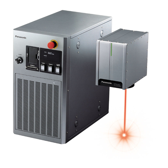
Panasonic LP-S Series Maintenance Manual
Laser marker
Hide thumbs
Also See for LP-S Series:
- Serial communication manual (205 pages) ,
- Operation manual (308 pages) ,
- Manual (9 pages)
Table of Contents
Troubleshooting

Related Manuals for Panasonic LP-S Series


Summary of Contents for Panasonic LP-S Series
- Page 1 Laser Marker Safety / Setup / Maintenance Guide LP-S series Please read these instructions carefully before using this product, and save this manual for future use. ME-LPS-SSM-8 No.9000-0066-16V 2021. 7 panasonic.net/id/pidsx/global...
-
Page 2: Preface
Preface Thank you for purchasing our product. For full use of this product safely and properly, please read this document carefully. This product has been strictly checked and tested prior to its delivery. However, please make sure that this product operates properly before using it. -
Page 3: Cautions In Handling
ALWAYS FOLLOW THESE IMPORTANT Cautions in Handling SAFETY PRECAUTIONS! To reduce the risk of injury, loss of life, electric shock, fire, malfunction, and damage to equipment or property, always observe the following safety precautions. The following symbols are used to classify and describe the level of hazard, injury, and property damage caused when the denotation is disregarded and improper use is performed. - Page 4 WARNING • Do not use this product anywhere where fire is strictly prohibited, near inflammable gas, objects or organic solvents such as thinner or gasoline, or in dusty place. There is a risk of fire. • Do not use this product except for water-resistant part in wet place. In addition, never conduct wiring or maintenance work with wet hands or when the product surface is wet.
- Page 5 WARNING • Remove the dust and/or gas which may be generated during the laser radiation with dust collector or exhauster. Use an appropriate dust collector or exhauster for dust or gas generated. Depending on the material of the objects, harmful dust and/or gas to the human body and the laser marker may be generated.
- Page 6 For the Proper Use of Product • Be sure to observe the following matters to prevent a failure or a malfunction of this product and to maintain the product performance properly. „ Usage environment • Do not use the product in a place with frequent vibrations or shocks. Moreover, please do not drop this product. It may affect the precision component and optical component inside, which could impair the performance or result in a failure.
- Page 7 For the Proper Use of Product • Be sure to observe the following matters to prevent a failure or a malfunction of this product and to maintain the product performance properly. „ Wiring • Verify that the cables are wired correctly before powering on. •...
- Page 8 Products) as occasioned by the improvements of Products. Consequently, when you place orders for these Products, Panasonic Industrial Devices SUNX asks you to contact one of our customer service representatives and check that the details listed in the document are commensurate with the most up-to-date information.
-
Page 9: Related Regulations And Standards
바라며 , 가정외의 지역에서 사용하는 것을 목적으로 합니다 . LP-S505-LS1 *1: Contact for CE: Panasonic Marketing Europe GmbH, Panasonic Testing Center Winsbergring 15, 22525 Hamburg, Germany *2: For LP-S200-LS1, LP-S202-LS1, LP-S205-LS1, LP-S500-LS1, LP-S502-LS1 and LP-S505-LS1, the printed copy of “Declaration of Incorporation of Partly Completed Machinery” is included in the package of this product. - Page 10 • Construct a safety system before using this product as it is a class 4 laser product. • While constructing the system, check ISO 13849-1 and ISO 11553-1, and take the required safety measures accordingly. Refer to “For the Safety Use of Laser Product” (P.16) for further details. „...
-
Page 11: How To Read This Document
In the text, multiple models may be described collectively, as shown in the table below. Note that the illustration and screen images may vary with model. Target model Description in the text LP-S200, LP-S200-CHN, LP-S200-SF, LP-S200-LS1 LP-S200 LP-S2xx LP-Sxxx LP-S series LP-Sxxx-CHN LP-S202, LP-S202-CHN, LP-S202-SF, LP-S202-LS1 LP-S202 LP-Sxxx-SF LP-S205, LP-S205-CHN, LP-S205-SF, LP-S205-LS1 LP-S205 LP-Sxxx-LS1... -
Page 12: Table Of Contents
Contents Preface ……………………………………………………………………………… 2 Cautions in Handling ………………………………………………………………… 3 Related Regulations and Standards ……………………………………………… 9 How to Read this Document ……………………………………………………… 11 For the Safety Use of Laser Product ………………………………………………16 Radiation information ……………………………………………………………… 16 Safety protection measures for users …………………………………………… 18 Safety functions on laser marker …………………………………………………... - Page 13 2-4-5 When using monitor and mouse …………………………………………… 66 2-4-6 Detaching / attaching the fiber unit ………………………………………… 67 2-5 Operation Method for Laser Marker …………………………………………73 2-5-1 Start-up & termination ……………………………………………………… 74 2-5-2 Operation procedure of test marking and run mode …………………… 76 Chapter 3 Connection for External Control …………………………78 3-1 Operation by External Devices ………………………………………………79 3-1-1 Operation method using external control device …………………………...
- Page 14 3-6-3 Interlock connector connecting samples ………………………………… 121 3-7 Connection for Serial Communication …………………………………… 122 3-7-1 RS-232C ……………………………………………………………………… 122 3-7-2 Ethernet ……………………………………………………………………… 124 Chapter 4 Maintenance …………………………………………… 126 4-1 Maintenance Items …………………………………………………………… 127 4-2 Maintenance Details of Parts ……………………………………………… 128 4-2-1 Protection glass of laser emission port …………………………………… 128 4-2-2 Replacement of the protection glass ………………………………………...
- Page 15 MEMO ME-LPS-SSM-8...
-
Page 16: For The Safety Use Of Laser Product
For the Safety Use of Laser Product This product falls into Class 4 laser (marking laser) and Class 2 laser (guide laser) based on the classifications of “Safety of laser products” IEC 60825-1. Perform the safety protection measure before using the system. Refer to “Safety protection measures for users”... - Page 17 The laser classified into the Class 2 refers to “Laser products that emit visible radiation in the wavelength range from 400 nm to 700 nm that are safe for momentary exposures but can be hazardous for deliberate staring into the beam.” Item LP-S series Remarks Wavelength...
-
Page 18: Safety Protection Measures For Users
Safety protection measures for users This product falls into Class 4 laser (marking laser) and Class 2 laser (guide laser) based on the classifications of the Safety of laser products by IEC 60825-1. Perform the safety protection measure shown below before using the system. For more detail instruction, refer to each of the standard. - Page 19 „ Power failure recovery For power failure occurs on the laser marker, construct a laser re-pumping system by manual operation for safety. „ Radiation direction of laser beam To assure safety, be sure to place the protective enclosure. Measures should be taken so that the direction of laser radiation can be seen and checked by others as well as an operator.
-
Page 20: Safety Functions On Laser Marker
Safety functions on laser marker This laser marker has the functions shown below for safety measures. Use these functions properly and operate the laser marker system safely. Head Controller Front Back ME-LPS-SSM-8... - Page 21 Internal shutter This is a shutter inside the head. The emission of laser beam is stopped by closing the internal shutter. Laser radiation indicator The operations of the laser radiation indicator are as follows: Laser marker status Head indicator Controller indicator Non-laser pumping Lights-out Lights-out...
- Page 22 10 to 14 Labels The following labels are attached to this product. (Contents of the labels vary depending on model.) If the head is placed out of the sight of operators, place the attached warning label on the immediately apparent place on the system. Warning / explanatory / aperture label : LP-S2xx type Warning / explanatory / aperture label : LP-S5xx type ME-LPS-SSM-8...
- Page 23 Warning / explanatory / aperture label : LP-SxxxW type Label for the protective housing Caution label for hot surface CAUTION Hot Surface Do not Touch Caution label for hand-carry : Certification and identification label LP-Sxxx(-SF/-CHN/-LS1) type only CAUTION △△△△ Do not lift this part. It may cause a fault.
- Page 24 „ Laser marker operation at inputting the safety functions Safety function Laser marker operation Release method Remarks Laser Stop 1 *1 Opened during laser emission Close Laser Stop 1 The power supply of CLOSE to OPEN • Laser pumping: OFF and input alarm reset.
- Page 25 „ Construction of interlock system For operating this product, construct the protective enclosure enclosing the range of the laser radiation for protecting the exposure caused by the reflection of the laser radiation from the marking object or the surrounding objects, and also construct the interlock system.
-
Page 26: Chapter 1 Specification
Chapter 1 Specification ME-LPS-SSM-8... -
Page 27: Product Model
160 mm x 160 mm „ Model name description LP-S 5 0 5 W -SF Series name of the product. LP-S series is the fiber laser marker. Represents laser output power class as follows. Laser output for processing 17W Laser output for processing 42W Represents marking field class as follows. -
Page 28: Product Configuration
1-2 Product Configuration This product is a laser marker which is designed to mark and process the object by radiating a laser beam to the target. The laser marker LP-S series consists mainly of the following units. Name Description Head It is the unit that radiates the laser beam. - Page 29 „ Optional items The following optional items (sold separately) are available for this product. To purchase them and for the detailed information, please contact our sales office. Optional items Model Touch panel console LP-ADP40 Air filter (for replacement) LP-AFT50X5 Protection glass of laser emission port (for replacement) *1 LP-ACV60 / LP-ACV50 / LP-ACV52 / LP-ACV55 Unit power cable (for replacement)
-
Page 30: Specification
1-3 Specification „ LP-Sxxx(-SF/-CHN/-LS1) type Model Item LP-S200 LP-S202 LP-S205 LP-S500 LP-S502 LP-S505 Laser type Yb : FIBER laser, λ =1064nm, Class 4 laser product Oscillator output Average output for Marking laser 17W (±5%) 42W (±5%) processing *1 Mode of operation Pulse oscillation Pulse cycle 2 μs to 50 μs... - Page 31 Model Item LP-S200 LP-S202 LP-S205 LP-S500 LP-S502 LP-S505 Required time for laser pumping Approx. 20 seconds 90V to 132V AC or 180V to 264V AC Power voltage (including voltage fluctuation range of ±10%) *9 Frequency: 50/60 Hz 100V AC 330VA or less 530VA or less Power consumption *10 200V AC...
- Page 32 „ LP-SxxxW(-CHN) type Model Item LP-S500W LP-S505W Laser type Yb : FIBER laser, λ =1070nm, Class 4 laser product Oscillator output Marking laser Average output for 42W (±5%) processing *1 Mode of operation CW oscillation Red semiconductor, λ =655nm, Class 2 laser product Guide laser, laser pointer Max.
- Page 33 Model Item LP-S500W LP-S505W 90V AC to 132V AC or 180V AC to 264V AC Power voltage (including voltage fluctuation range of ±10%) *9 Frequency: 50/60 Hz 100V AC 470VA or less Power consumption 200V AC 650VA or less Grounding method Head and controller: Direct earth Cooling method Head: Natural air-cooling, Controller: Forced air-cooling...
- Page 34 „ About protection grade (dustproofness, waterproofness and oilproofness) The marker head is designed to be dustproof and waterproof to JIS/IEC protection grade IP67 and oilproof to JIS IPXXG. (Excluding the controller) The test methods for determining the dustproof, waterproof and oilproof characteristics are specified in JIS C 0920 and IEC 60529.
-
Page 35: Outer Dimensional Drawing
1-4 Outer Dimensional Drawing 1-4-1 Head „ LP-Sxxx(-SF/-CHN/-LS1) type: LP-S200 / LP-S500 / LP-S202 / LP-S502 / LP-S505 / LP-S205 Unit: mm (391) 215 20 48 (4) 34 (18) 113 18.5 109 30 60 60 64 40 40 40 40 Description Work distance: LP-S200 / LP-S500 : 190 mm... - Page 36 „ LP-SxxxW(-CHN) type: LP-S500W / LP-S505W Unit: mm (165) (18) 18.5 Description Work distance: LP-S500W : 193 mm LP-S505W : 357 mm Center of marking field Marking field (X, Y) : LP-S500W : 90 mm x 90 mm LP-S505W : 160 mm x 160 mm Laser pointer emission port: φ26 mm (Aperture diameter: φ20 mm) Laser emission port diameter: LP-S500W : φ87 mm...
-
Page 37: Fiber Unit
1-4-2 Fiber unit When the fiber unit is detached from the head „ LP-Sxxx(-SF/-CHN/-LS1) type: LP-S200 / LP-S500 / LP-S202 / LP-S502 / LP-S505 / LP-S205 Unit: mm (417) (71) 25 69 „ LP-SxxxW(-CHN) type: LP-S500W / LP-S505W Unit: mm Description Fiber unit protection cap : This cap should be removed when the scanner unit is connected. -
Page 38: Controller
1-4-3 Controller „ LP-S series (27) Unit: mm (170) 390 225 (29) 220 (38) 200 200 98 4x 30 Description Rubber feet installation screw hole (4 holes in bottom and each side): M5, depth 6 The rubber feet for controller can be installed on base or both side surfaces. -
Page 39: Cable
1-4-4 Cable „ AC power cable Attached AC power cable varies depending on each model. Please select a cable compliant with the standards in the country or region where it is used. Rating 125V, PSE standards and CSA/UL standards compatible cable (North America, Japan) : Attached to LP-Sxxx(-SF) / LP-SxxxW type Rating 250V, VDE standards compatible cable (Europe) : Attached to LP-Sxxx(-SF) / LP-SxxxW / LP-Sxxx-LS1 type... -
Page 40: Console (Option)
1-4-5 Console (option) Model name: LP-ADP40 Unit: mm (41.5) 80±0.8 (253) (171) (15) (55) Description Pen holder attaching nut M4, depth 6 (both left and right sides) Attaching nut (4 positions) M4, depth 6 Controller connecting cable ME-LPS-SSM-8... -
Page 41: Chapter 2 Preparation
Chapter 2 Preparation ME-LPS-SSM-8... -
Page 42: Package
2-1 Package Before using this product, be sure to check the packed objects as shown below. This product is delivered in a set of head unit and controller unit packed in one box. If you find any missing item in the package, please contact the dealer you purchased it or our sales office. •... - Page 43 Logo Data Conversion Software Export VEC Logo Data Editing Software PDF manual Language LP-S series Safety / Setup / Maintenance Guide Japanese/English/Chinese LP-M/S/Z series Operation Manual LP-M/S/Z series Serial Communication Guide Laser Marker NAVI plus Operation Manual Logo Data Conversion Software Operation Manual...
-
Page 44: Name Of Each Part
2-2 Name of Each Part 2-2-1 Head Fiber unit Scanner unit Signal connector: SIGNAL This is the terminal for communicating between head and controller. Connect the attached signal cable. Power connector: POWER This is the connector for supplying the power to the head. Connect the attached unit power cable. - Page 45 Focus adjusting control (Only for LP-Sxxx(-SF/-CHN/-LS1) type) The control for adjusting the distance from the work. Laser emission port protection glass This glass protects laser emission port from dirt or damage. Attach this glass always. Remove the plastic cover on this glass before operation. 10.
-
Page 46: Controller
2-2-2 Controller „ Front Key switch: POWER This key switch is used to start the laser marker system. Turn ON (|) the switch to start-up the system, and turn OFF (O) the switch to shutdown the system. Only when the key switch is turned OFF (in O position), the key can be pulled out. When the laser marker is not in use, the key should be in safekeeping by a laser safety manager. - Page 47 Laser pumping switch (with white LED): LASER This is the switch for starting laser pumping. LED flashes (approx. 20 sec.) in white when the switch is pressed, and it lights up when the laser irradiation becomes enabled. Remote switch (with white LED): REMOTE This is the switch for activating communication control and I/O control.
- Page 48 „ Rear USB connector A (2 connectors) This is the terminal for connecting the USB media or USB mouse. For registering or saving data in the laser marker, connect a commercially available USB. You can also connect a USB mouse when setting by using a commercially available monitor. A USB port is also mounted on the front.
- Page 49 AC power terminal: AC INPUT Terminal for connecting AC power supply. Connect the attached AC power cable. 90V to 132V AC or 180V to 264V AC (including ±10% voltage fluctuations), 50Hz/60Hz (The voltage and frequency switch automatically.) Be sure to connect the ground pin of the AC power cable to earth permanently. 10.
-
Page 50: Dip Switch
2-2-3 DIP switch Set the operational options of the laser marker with the DIP switch equipped on the controller rear side. • A plastic cover is installed on the DIP switch. Install this cover always to avoid the dust penetration to the controller. DIP switch •... - Page 51 Item Description No. 5 Select the setting method of the remote mode. Use the input signal of X5 “REMOTE IN” on I/O terminal. Use the remote switch on the front of the controller. • When DIP switch No. 6 is ON, keep DIP switch No. 5 OFF. No.
-
Page 52: Installation
2-3 Installation 2-3-1 Installation environment This product can be used in the following environment. Item Installation environment conditions Operating ambient temperature *1 0°C to +40°C Operating ambient humidity *1 35 to 85%RH Ambient temperature for storage *1 -10°C to +60°C *2 Protection degree Head: IP67G (Excluding the controller) Other conditions... -
Page 53: Installation Method
2-3-2 Installation method Lens cap * • Check the length of the screw and install it. Using improper screws and forcibly tightening them might damage the product. „ Head • Install the head on a plate with a thickness of 10 mm to 15 mm which is made of aluminum or other material with radiation performance equivalent to that of aluminum. - Page 54 „ Spacers [LP-ASP10, LP-ASP11] (option) 2-type spacers for the LP-S series are available (options). Installing it to the head allows its work distance to adjust +10mm. Attaching the spacer to this product makes the work distance equal to that for the older model of LP-F10 and LP-F10R. For details,please contact our sales office.
-
Page 55: Installation Direction
2-3-3 Installation direction For making use of laser marker safely and fully, install the laser marker to either direction shown below. „ Head The head can be installed to all directions (up, down, left, and right). • Install the product so that the laser beam path does not cross the eye height. WARNING •... -
Page 56: Installation Space
2-3-4 Installation space For the appropriate air cooling, provide space around the device as shown in the following figure. „ Head „ Controller LP-Sxxx 500mm 50mm 50mm 150mm 300mm LP-SxxxW 50mm 300mm 50mm Intake air 150mm 50mm Exhaust 50mm 150mm •... -
Page 57: Marking Field And Marking Center Position
2-3-5 Marking field and marking center position Specified point LP-S200/S500 LP-S500W LP-S202/S500 LP-S205/S505 LP-S505W A : Work distance 190 mm 193 mm *1 130 mm 350 mm 357 mm *2 B : Marking field (X, Y) 90 mm × 90 mm 55 mm ×... -
Page 58: Lasing Position Check
2-3-6 Lasing position check „ Dual pointer function Dual pointer shows the rough indication of the work distance (distance from the head base to the marking surface). It displays the red point emitted in oblique and the red circle emitted perpendicularly from the head. The distance where the laser point is closest to the center of the circle represents the guide of the work distance. -
Page 59: Focus Adjustment Function
2-3-7 Focus adjustment function [Function specific to LP-Sxxx type] * This function is not implemented in the LP-SxxxW type. With this function, the distance from work (focal length) can be adjusted without moving up/down the head. Marking energy density can be reduced by moving the focus point of the laser spot with the specified distance between the works and changing the spot diameter. - Page 60 Remove the existing O-ring and install a new O-ring (S). • The O-ring cannot be reused. Be sure to use new one. • Replacement O-ring is supplied with this product. After using the supplied O-ring, you can purchase a “Set of gaskets” separately.
-
Page 61: Connecting Laser Marker
2-4 Connecting Laser Marker • Prior to wiring and/or cable connecting work, ensure that all the power WARNING switches are turned off. Otherwise, electrical shock may result. 2-4-1 Connecting head, controller, terminal block • For the connection of this product, use the dedicated cables attached to the product or the specified optional cables. •... -
Page 62: Connecting Ground And Power Supply
2-4-2 Connecting ground and power supply This section describes how to connect ground and power supply. For the AC power cable, use the attached AC power cable. The power terminal, protective conductor terminal and frame ground terminal are located on the back side of the unit as shown below. - Page 63 Connect the three wires to the terminals. The signs of “L (black)”, “N (white)” and “PE (yellow/green)” show in the cables. Connect each cable to the appropriate terminal. Screw size: M4 Tightening torque: 1.2N·m to 1.8N·m • For the AC power supply cable, use the attached AC power cable or a cable with the enough rating capacity to fulfil the power voltage specification of this product.
-
Page 64: When Using Pc
2-4-3 When using PC To use the PC installed the software in attached To USB connector B CD-ROM “Laser Marker Utility” with online status, connect the attached USB cable to the front side of the controller. Front side of controller USB cable „... -
Page 65: When Using Console
2-4-4 When using console • When using the console LP-ADP40 (optional item), connect the return harness to the rear of the controller. • Do not take out and put in the console in being powered on. Description Front side of controller Rear side of controller LP-ADP40: Optional touch panel console Return harness... -
Page 66: When Using Monitor And Mouse
2-4-5 When using monitor and mouse • Be sure to check the operation status when using the monitor and mouse beforehand. This connection status does not warrant all operations of VGA monitor and USB mouse. • Do not take out and put in a monitor, and a mouse in being powered on. •... -
Page 67: Detaching / Attaching The Fiber Unit
2-4-6 Detaching / attaching the fiber unit The fiber unit of this product can be removed from the head at the installation temporarily. At the delivery state, the fiber unit is connected to the head. Fiber unit • The fiber cable cannot be removed from the controller side. Trying to disconnect the controller unit from the fiber cable forcibly may cause a failure. - Page 68 Procedure for Fiber Unit Detaching Use a hexagon wrench to loose the 4 locking screws on the fiber unit. Handhold the fiber unit and remove it from the head. LP-Sxxx(-SF/-CHN/-LS1) type LP-SxxxW(-CHN) type • Do not remove the screws other than the specified ones. It may cause failure. •...
- Page 69 Install the scanner unit protection cover. Use a hexagon wrench to install the 4 screws. Tightening torque: 0.7N·m to 1.3N·m Protection cover for the scanner unit • Attach the protection cover always when the fiber unit is detached from the scanner unit. •...
- Page 70 Procedure for Fiber Unit Attaching Remove the scanner unit protection cover. Keep the scanner unit protection cover for the next use. Protection cover for the scanner unit • Make sure that no foreign matter such as fingerprint, dust, grease or oil is attached to the glass inside of the head. If the glass is contaminated, blow dusts with an air duster for optics.
- Page 71 Remove the fiber unit protection cap from the fiber unit. Keep the fiber unit protection cap for next use. LP-Sxxx(-SF/-CHN/-LS1) type LP-SxxxW(-CHN) type Protection cap for the fiber unit Protection cap for the fiber unit Make sure that the fiber cable is not twisted. •...
- Page 72 After the temporary fitting of the fiber unit by tightening loosely, evenly tighten the screws in a criss-cross manner to the specified torque of 1.5 N·m. LP-Sxxx(-SF/-CHN/-LS1) type LP-SxxxW(-CHN) type • Not to break the screw head, use the end-rounded tightening tool and insert it to the screw head as straight as possible. •...
-
Page 73: Operation Method For Laser Marker
2-5 Operation Method for Laser Marker The laser marker can be controlled by the following method: Control by the manually screen operation To irradiate the laser by the screen operation, select the control methods from the followings: • Test marking Test marking executes the laser radiation manually with the selected file. -
Page 74: Start-Up & Termination
2-5-1 Start-up & termination • It is obligated by IEC/FDA/JIS that laser products shall incorporate a key- actuated master control. Actuation of this product is basically controlled by the key switch located on the front of the controller. However, in considering WARNING situations when the laser marker is operating as a part of a larger system, the laser marker turns on if the key switch is already in ON position, and power is... - Page 75 „ Termination Turn off the laser pumping switch on the controller. • Under the remote control mode, turn off the laser pumping by using LASER IN (X9) on I/O terminal or the serial communication command for the laser pumping (LSR). If you want to save the file, move to “FILE”...
-
Page 76: Operation Procedure Of Test Marking And Run Mode
2-5-2 Operation procedure of test marking and run mode This section describes the basic operation procedures with the display operation connected to the controller. Flow Chart Turn on power with key switch on controller. For test marking For Run mode operation File selection Edit the file Edit and overwrite the file... - Page 77 „ Test marking procedure Test marking executes the laser radiation manually with the selected file. Select “TEST” of the marking mode in the lower part of the screen. Turn ON the laser pumping switch on the controller to start laser pumping. To start marking, click “START”.
-
Page 78: Chapter 3 Connection For External Control
Chapter 3 Connection for External Control ME-LPS-SSM-8... -
Page 79: Operation By External Devices
3-1 Operation by External Devices 3-1-1 Operation method using external control device To control the laser marker with the external control device, the following connecting methods are applicable: External control using I/O : Remote mode operation Controls the laser marker from external devices such as PLC using various I/O signals loaded into the laser marker. For details, refer to “3-3 Control by I/O”... -
Page 80: Operation Procedure With External Control
3-1-2 Operation procedure with external control „ Operation example when controlling the laser marker from external control devices such as Turn ON key switch of laser marker controller Remote mode ON Refer to “3-2-3 Shift to remote mode” (P.85). I/O control Control by serial communication commands Select file Laser pumping ON... -
Page 81: Before External Control
3-2 Before External Control The following settings are required before the external control by using I/O or communication commands. „ Setting flow to start external control DIP switch setting • DIP switch No. 2: Select control method, I/O or command for some specific operations. •... -
Page 82: Dip Switch Setting
3-2-1 DIP switch setting Set the operational options for the external control with the DIP switch equipped on the controller rear side. • The initial setting of all DIP switches is OFF. • Turn OFF the power at DIP switch setting. •... - Page 83 With DIP switch No. 5, select the setting method of the remote mode. DIP switch No. 5 Setting method of remote mode Use the input signal of REMOTE IN (X5) on I/O terminal. OFF (initial setting) Use the remote switch on the front of the controller. •...
-
Page 84: Communication Condition Setting
3-2-2 Communication condition setting To control the laser marker by using I/O or communication commands, configure the following items in advance on the environment setting screen. Select “ENVIRON” on the right menu. Select “ENVIRON 3”. To use I/O signals, configure the following output conditions: •... -
Page 85: Shift To Remote Mode
3-2-3 Shift to remote mode To control the laser marker externally using I/O or serial communication commands, set the operation mode to the remote mode in one of the following methods. Select the method to switch to the remote mode by setting the DIP switch on the rear side of the controller. Use the remote switch on the front of the controller. -
Page 86: Control By I/O
3-3 Control by I/O 3-3-1 Type of I/O interfaces This product has the following I/O interfaces on the rear side of the controller. Name Description I/O terminal Input and output terminals to control the laser marker externally. Refer to “3-3-2 Terminal and connector for I/O” (P.87). I/O connector Interlock connector 1 Input and output terminals to construct the interlock system to stop the laser... -
Page 87: Terminal And Connector For I/O
3-3-2 Terminal and connector for I/O The I/O terminal block and the I/O connector are available as the external control I/O interface of this product. • I/O terminal block: Loaded with the basic input/output to control the laser marker. • I/O connector: Loaded with the input/output for data configuration such as selecting a file number and the input/output for the specific functions. - Page 88 „ Connector specifications and models Connector position Model Manufacturer name I/O terminal block On the laser marker side • Input: Phoenix Contact MSTBVA 2.5/20-G-5.08-LR • Output: MSTBVA 2.5/14-G-5.08-LR User side Attached accessories • Input: FKC_2.5/20-ST-5.08-LR • Output: FKC_2.5/14-ST-5.08-LR I/O connector On the laser marker side: ―...
-
Page 89: Signals On Input/Output Terminal
3-3-3 Signals on input/output terminal „ List of signals Name Description Name Description 24V OUT Internal power +24V 0V OUT Internal power 0V IN COM. Input common OUT COM. Output common 0V OUT Internal power 0V 24V OUT Internal power +24V RESERVE System reservation STAND BY... - Page 90 „ Input signal operation in I/O terminal • The ON/OFF listed in this section refers to the ON/OFF operations. It does not refer to the voltage level (High/Low). Terminal No. Name / Description 24V OUT: Internal power (power for input/output) + 24V DC (max. output current 300mA) Power to operate the laser marker independently.
- Page 91 Terminal No. Name / Description SHUTTER A: Shutter control input A The shutter inside head is opened while the terminal remains in ON position. (The terminal control is available during shutter control Input B ON). There is a delay time of around 200ms to max. 1 second from turning ON/OFF of SHUTTER A/B IN for the actual shutter open / close operation time.
- Page 92 „ Output signal operation in I/O terminal • The ON/OFF listed in this section refers to the ON/OFF operations. It does not refer to the voltage level (High/Low). Terminal Name/Description 0V OUT: Internal power (power supply for input/output) 0V Power to operate the laser marker independently. Y1 and X3 are the common terminal connected internally.
- Page 93 Terminal Name/Description MARKING: Marking output This signal is turned to ON during marking (laser radiation). If the marking time is shorter than the specified one-shot output time, MARKING OUT remains ON until the one-shot output time ends. MARK END: Marking end output Output ON when marking ends.
-
Page 94: Signals On I/O Connector
3-3-4 Signals on I/O connector „ List of signals Name Name IN COM. TIME HOLD Input common Time hold input RESERVE Set input System reservation GUIDE Guide laser input RESERVE System reservation Date gap output CEND 0 / 4 Counter 0 or 4 end output CEND 1 / 5 Counter 1 or 5 end output CEND 2 / 6... - Page 95 „ Input signal operation in I/O connector • The ON/OFF listed in this section refers to the ON/OFF operations. It does not refer to the voltage level (High/Low). Terminal No. Name / Description IN COM.: Input common The common terminal for each input of the I/O terminal and I/O connector. This terminal is internally connected to the input common on the input terminal block.
- Page 96 Terminal No. Name / Description Count-up value correction (SELECT 1 input: ON) Count-down value correction (SELECT 0 input, SELECT 1 input: ON) Input this number when you change the next marking value of the counter function. The counter value is specified by the step times of count-up or count-down. The step value indicates a value to increase or decrease per one counting-up or counting-down.
- Page 97 Terminal No. Name / Description Data number for Rank /External offset function (SELECT 0 input: ON) The rank/external offset function is a function that switches marking characters (rank) or the coordinates (external offset) using the input terminal D0 to D15. Configure the character or coordinate patterns to the data number corresponding to D0 to D15 in advance.
- Page 98 Terminal No. Name / Description 20 to 22 SELECT 0, SELECT 1, SELECT 2: select 0 to 2 input Select the corresponding number input from D0 to D15 and the guide laser radiation details. • Select the number input target Input SELECT 0 to 2 corresponding to the number input shown below.
- Page 99 „ Output signal operation in I/O connector • The ON/OFF listed in this section refers to the ON/OFF operations. It does not refer to the voltage level (High/Low). Terminal Name/Description RESERVE: System reservation Do not connect externally. GAP OUT: Date gap output Output ON as a warning when date different from preset date in the internal clock is marked after the date changes with the time hold input ON.
-
Page 100: Input Rating And Input Circuit
3-3-5 Input rating and input circuit The input rating and input circuit for the Input terminal and I/O connector are shown as follows: „ Input rating Item Terminal block, I/O connector input Input form Bidirectional photo-coupler Input ON voltage Difference of voltages between input and input common: 19.6V or more Input OFF voltage Difference of voltages between input and input common: 4V or less Rated input voltage... -
Page 101: Output Rating And Output Circuit
3-3-6 Output rating and output circuit The output rating and output circuit for the output terminal block and I/O connector are shown as follows: „ Output rating Item Output terminal I/O connector output Output form NPN / PNP Photo-coupler (insulated output) Protection function for short-circuit None Max. -
Page 102: Connecting I/O Terminals
3-4 Connecting I/O Terminals WARNING • Make sure that the power is turned OFF at wiring. 3-4-1 Factory default wiring The following terminals are connected by short bars at the factory default. Remove these short bars when you connect them to an external device. •... -
Page 103: Connecting Common Terminals
3-4-2 Connecting common terminals Connect IN COM.(X2) and OUT COM.(Y2) respectively to the power supply to supply power for input and output. Common terminals (IN COM. or OUT COM.) on the I/O connector and the I/O terminal block are connected internally. Supply the power to the one side of IN COM. -
Page 104: Sensor Connection Example
3-4-3 Sensor connection example „ Use the sensor as a marking trigger (operate the sensor by the internal power) NPN connection 0V OUT 24V OUT OUT COM. IN COM. 0V OUT Sensor TRIG. IN I/O terminal block PNP connection 24V OUT OUT COM. -
Page 105: Connection Example Of Laser Stop Terminals
3-4-4 Connection example of laser stop terminals The following terminals are used to stop the laser radiation or disable the laser radiation temporarily. When these terminals are disconnected, the laser radiation will be disabled. Between LASER STOP terminals and OUT COM., an external device, such as door switch or laser stop switch can be connected. -
Page 106: Timing Chart
3-5 Timing Chart • ON/OFF on the timing chart does not intend to High/Low of voltage level. It intends to ON/OFF of operation. • In the following timing charts, the timing of output operation corresponding to the each input has a small delay of 0 ms or more. - Page 107 Item Period Remarks approx. 75 sec. System Starting Time. Change to the remote mode after system start-up. approx. 20 sec. The time from turning ON the pumping input to completion of pumping. LP-Sxxx type: approx. 20 seconds / LP-SxxxW type: approx. 15 seconds ―...
-
Page 108: Marking Trigger Input
3-5-2 Marking trigger input READY OUT TRIG. IN MARKING OUT WARNING OUT (Active Low) Item Period Remarks 10 ms or more Keep the ON status for 10 ms or more. 2 to 510 ms It outputs a warning to notify that an invalid trigger was input when a marking trigger was input during trigger processing. -
Page 109: Guide Laser
3-5-4 Guide laser SHUTTER A IN SHUTTER B IN SELECT 0 to 2 IN GUIDE IN READY OUT (Open) SHUTTER OUT *1 (Close) *1 : Shutter output signal has around 200ms to max. 1 sec. delay from each input signal for the shutter open / close operation time. -
Page 110: Select File
3-5-5 Select file SELECT 0 to 2 D0 to D15 IN SET IN TRIG. IN READY OUT MARKING OUT SET OK OUT Item Period Remarks 0.5 ms or more After a lapse of 0.5ms or more from specifying SELECT 0 IN to SELECT 2 IN and D0 IN to D15 IN, turn on SET IN. -
Page 111: Time Hold Input And Date Gap Output
3-5-6 Time hold input and date gap output Actual date Day 1 Day 2 Example: 15 o’clock at Day 1 8 a.m. at Day 2 TIME HOLD IN TRIG. IN Marking with Marking with MARKING OUT the time at the time at (Marking with the time (3 p.m. -
Page 112: Count-Up/Count-Down Value Correction
3-5-8 Count-up/count-down value correction SELECT 0 to 2 IN D0 to D7 IN (Counter No.) D8 to D15 IN (Count-up/count- down step times) SET IN TRIG. IN *3 SET OK OUT *3 READY OUT MARKING OUT Item Period Remarks 0 ms or more Keep the input until the SET OK turns ON. -
Page 113: Counter Reset Input
3-5-9 Counter reset input TRIG. IN SELECT 0 to 2 D0 to D7 IN (Counter No.) SET IN READY OUT MARKING OUT SET OK OUT Item Period Remarks 10 ms or more Keep the ON status for 10 ms or more. 0 ms or more Keep the input until the SET OK turns ON. -
Page 114: Rank / External Offset Marking
3-5-10 Rank / external offset marking TRIG. IN SELECT 0 to 2 IN Data A Data B Data C D0 to D15 IN *2 SET IN READY OUT Data A Data B Data C MARKING OUT SET OK OUT Item Period Remarks ―... -
Page 115: Safety Function Input (Laser Stop 1)
3-5-11 Safety function input (laser stop 1) [Input] LASER IN SHUTTER A IN SHUTTER B IN TRIG. IN ALARM RES. IN (Close) LASER STOP 1 IN *1 (Open) [Output] READY OUT LASER OUT (Open) SHUTTER OUT *2 (Close) Marking interrupted MARKING OUT MARK END OUT WARNING OUT... -
Page 116: Safety Function Input (Laser Stop 2)
3-5-12 Safety function input (laser stop 2) [Input] LASER IN SHUTTER A IN SHUTTER B IN TRIG. IN ALARM RES. IN (Close) LASER STOP 2A IN (Open) (Close) LASER STOP 2B IN (Open) [Output] READY OUT LASER OUT (Open) SHUTTER OUT *1 (Close) Marking... -
Page 117: Safety Function Input (Interlock)
3-5-13 Safety function input (interlock) [Input] LASER IN SHUTTER A IN SHUTTER B IN TRIG. IN CLOSE INTERLOCK INPUT *1 OPEN ALARM RESET IN [Output] READY OUT LASER OUT (Open) SHUTTER OUT *2 (Close) Marking interrupted MARKING OUT MARK END OUT ALARM OUT (Active Low) *1 : Control Interlock 1 and 2 on LP-Sxxx-SF/LP-Sxxx-LS1 type with the same flow as the Interlock input above described. -
Page 118: Interlock Connector
3-6 Interlock Connector 3-6-1 Connector type and signals * This view is facing the connecting surface. Laser marker side User side: Attached accessory (Female connector) (Male Connector) Laser marker side connector SRCN2A13-3S Japan Aviation Electronics Industry, Ltd. [Attached item] User side connector SRCN6A13-3P •... - Page 119 For LP-Sxxx-SF/LP-Sxxx-LS1 type Name and description INTERLOCK 1 COM. (on Interlock 1 connector) INTERLOCK 2 COM. (on Interlock 2 connector) Common terminal for the interlock connector. Connect each INTERLOCK IN (No.3) and INTERLOCK COM. (No.1) with the non-voltage contact (relay output terminal etc.) of the safety devices such as door, switch or safety PLC.
-
Page 120: Input And Output Circuit Of Interlock
3-6-2 Input and output circuit of interlock Except LP-Sxxx-SF/LP-Sxxx-LS1 type Inner circuit of laser marker +24V DC Pin No. 1. INTERLOCK COM. Relay Pin No. 3. INTERLOCK IN 42mA Power supply for laser source For LP-Sxxx-SF/LP-Sxxx-LS1 type Inner circuit of laser marker +24V DC Pin No. -
Page 121: Interlock Connector Connecting Samples
3-6-3 Interlock connector connecting samples Connect between INTERLOCK IN and INTERLOCK COM. with the non-voltage contact (relay output terminal etc.) of the safety devices such as door, switch or safety PLC. • INTERLOCK IN on the interlock connector are connected to the operating coil of the internal relay in the controller. Connect INTERLOCK IN (No.3) and INTERLOCK COM. -
Page 122: Connection For Serial Communication
3-7 Connection for Serial Communication To control the laser marker externally by using communication command, RS-232C or Ethernet can be used. • For communication with external devices, select either RS-232C or Ethernet port. (They cannot be used at the same time, or switched.) The port selected in the environment setting screen indicates the valid communication port. - Page 123 „ Connecting to external control devices • To connect the laser marker to the PC for control, use a commercially available RS-232C cross cable (9-pin). • In case of connecting to PLC, a type of the cable (straight or cross) differs depending on a manufacturer or a model. Please follow the PLC manual.
-
Page 124: Ethernet
3-7-2 Ethernet „ Port specifications When Ethernet perform communication control of the laser marker, use an Ethernet port. Green LED Orange LED RJ-45 8-pole connector Rear of controller Light color Description Green Lights up while 1000 BASE-T Management port is in link-up state. Orange Blinks while there is activity on this port. - Page 125 „ Connecting to external control devices • To connect an external device and the laser marker directly one to one: Use a Category 5e or higher cross cable for connection. • If the external control device has the AutoMDI/MDI-X function, either a straight cable or a crossed cable can be connected to the laser marker.
-
Page 126: Chapter 4 Maintenance
Chapter 4 Maintenance ME-LPS-SSM-8... -
Page 127: Maintenance Items
4-1 Maintenance Items Listed below are typical parts that require cleaning or replacement depending on the usage environment or duration of service of the laser marker. Some parts are maintainable by the customer, and other parts are required to be repaired or replaced by our service representative, depending on the types of parts and the defects. -
Page 128: Maintenance Details Of Parts
4-2 Maintenance Details of Parts • Maintenance work must be conducted with the power to the laser marker turned OFF, and the AC power cable disconnected. Doing so may cause exposure to the laser beam or electrical shock. WARNING • Do not insert your hands or objects to the exhaust port of each unit or the gaps between units during the maintenance work. - Page 129 „ Cleaning steps for protection glass of laser emission port (Daily maintenance) In order to maintain stable marking quality, the protection glass of laser emission port needs to be cleaned regularly according to the usage environment. Turn OFF the key switch of the controller, and disconnect the AC power cable. Clean the laser emission port with an air duster for optics, and wipe it lightly with a soft cloth.
-
Page 130: Replacement Of The Protection Glass
4-2-2 Replacement of the protection glass In case that any contamination that cannot be cleaned adhering to the protection glass of laser emission port or any damage on the glass surface, replace the protection glass according to the following procedure. „... - Page 131 Install a new O-ring (L) in the inside groove of the protection glass. O-ring O-ring Groove Groove LP-ACV60 LP-ACV50 / LP-ACV52 / LP-ACV55 • The O-ring cannot be reused. Be sure to use new one. Replacement O-rings are attached with the laser marker and with the replacement protection glass.
-
Page 132: Air Filter
4-2-3 Air filter One air filter is placed in the air-cooling area of the controller. „ Effect from deterioration The air filter soiled with dust may reduce the cooling effect of the air-cooling fan. This may cause the performance to degrade, or failure of the laser marker. -
Page 133: Air-Cooling Fan And Intake Vent
4-2-4 Air-cooling fan and intake vent The air-cooling fans are equipped on the controller. If any dust adhered onto the fans or intake vent may decrease the cooling performance and cause the performance to degrade, or failure of the laser marker. Clean them regularly according to the usage environment. -
Page 134: Cleaning Of Head
4-2-5 Cleaning of head • Do not touch the head surface right after the operation. It becomes hot CAUTION and may cause burn injury. Heat sink Natural-cooling system is used in the head, thus the cooling effect will significantly drop if dust or oil is adhered to the surface. -
Page 135: Laser Oscillator
4-2-7 Laser oscillator A fiber laser oscillator is installed in the controller. The laser beam output from the oscillator is delivered through the fiber cable to the head. The laser is scanned and focused in the head and emitted to the target materials. „... -
Page 136: Laser Output Optimize
4-2-8 Laser output optimize [Function specific to LP-Sxxx type]* This function is not implemented in the LP-SxxxW type. Using “Laser Output Optimize” function improves the accuracy of “Laser output measurement/correction” results. After the installation, replacement or moving of laser marker, use this “Laser Output Optimize” function by following the procedures as described below. - Page 137 Install the laser power meter to measure the laser power. Place the detector of the laser power meter at the following distance, i.e. one-third to half of the focal length (specified work distance) of the laser marker. Laser marker model name Setting distance of detector of the power meter LP-S502, LP-S202 Approx.
- Page 138 After setting the laser power meter, press [NEXT]. Press [LASER CHECK]. Press [START] to radiate the laser and measure the output power with the laser power meter. Laser radiation is terminated by pressing [STOP]. • Be sure to wear protective goggles. WARNING •...
- Page 139 Adjust the “Power Correction Rate” so that the measurement results by the power meter fall within the optimum value. Input range: 50 to 200 [%] Press [EXECUTE] after changing the power correction rate. • In case when the measurement results cannot be in the optimum range even after changing the power correction rate, the laser marker may have a problem with the laser output performance.
-
Page 140: Power Monitor Calibration
4-2-9 Power monitor calibration [Function specific to LP-SxxxW type]* This function is not implemented in the LP-Sxxx type After the installation, replacement or moving of laser marker, the accuracy of the power monitor measurement result may decrease. In that case, calibrate the power monitor. When the power monitor calibration is performed, the measurement is shown assuming the power at that point to be 100%. -
Page 141: Galvano Scanner
4-2-10 Galvano scanner Galvano scanner is a scanner for radiating the laser beam along the coordinates of the setting data. The galvano scanner scans the setting data by controlling the angle of galvano mirror mounted onto the axis of rotation of motor with two axes to generate characters or drawings for the laser marking. -
Page 142: Internal Shutter
4-2-11 Internal shutter The internal shutter is opened and closed by the rotary solenoid to shut off the path of laser beam. „ Effect from deterioration When the rotation torque of the rotary solenoid declines, the opening/closing speed of the internal shutter is decreased or the shutter may not work. -
Page 143: Replacement Of Fuse
4-2-13 Replacement of fuse Replace fuse of the controller when blowing. The power of the laser marker cannot be turned on if the fuse is blown. „ Models of replacement parts Be sure to use the following type of fuse: If the user applies any other fuses than the specified one, failure might result. Laser marker model Type Model... -
Page 144: Obtaining Backup Data
4-3 Obtaining Backup Data Data in the laser marker can be backed up and restored to the other laser marker. Obtain and keep a backup of data registered in the laser marker periodically in case of replacing laser markers for repairing and maintaining purposes. -
Page 145: Serial No. Checking Method
4-4 Serial No. Checking Method Notify our sales office or representatives of the laser marker serial No. for inspection or repair. The head and controller is delivered with the same serial numbers. „ Check it on laser marker The serial No. of the laser marker is written on the area marked by a circle in the figure below. Top side of head Rear of controller „... -
Page 146: Disposal Of Laser Marker
4-5 Disposal of Laser Marker To dispose of the laser marker, in accordance with the regional regulation, please request the industrial waste disposer. Dispose of the laser marker as industrial waste, and never discard it with regular trash. • Be sure to delete all registered data when transferring or discarding the laser marker. Retained data might result in illegal read out and leaking of information by a third-party with malicious intent. - Page 147 „ Detaching method of batteries In case of disposal of this product in the European Union, remove the battery with the following procedures and segregate it properly in accordance with the EU Battery Directive (2006/66/EC). • When detaching the exhausted battery, be sure to disconnect the AC power WARNING cable so that the power cannot be supplied to the device.
-
Page 148: Troubleshooting
Troubleshooting ME-LPS-SSM-8... -
Page 149: Troubleshooting
Troubleshooting If any operation errors occur, check items below. When the problems cannot be resolved by following the below measures, please contact our sales office. „ Start-up Troubles Causes Measures Power cable is not connected. Connect the power supply cable. Power supply is not Key switch is not turned on. - Page 150 „ Display Troubles Causes Measures See remedial action against “Laser marker fails to Laser marker has not be started. start up”. Power cable of console is not Check that console cable is securely connected Touch panel console connected. to connector [CONSOLE] on front of controller. shows nothing.
- Page 151 Causes Measures Remove obstacle between head of laser marker Obstacle hinders laser beam. and object. For LP-S series: Remove lens cap. Lens cap has not been removed. Adjust distance between bottom surface of laser Distance to object is not appropriate.
- Page 152 Troubles Causes Measures Check connections with external equipment for mis-connection, disconnection or contact failure due to any loose connector. When the marking trigger is input from the input terminal, check if marking trigger signal meets When the laser marker is under the write conditions.
- Page 153 „ Marking quality Troubles Causes Measures Refer to the “Safety / Setup / Maintenance Guide” “Maintenance” and clean contaminants off the laser emission port. Laser emission port is not clean. If contaminants persist, replace lens and/or laser emission port protection cover (glass). Contact our sales office.
- Page 154 Troubles Causes Measures Remove obstacle between head of laser marker Obstacle hinders laser beam. and object. Refer to the “Safety / Setup / Maintenance Guide” Character is partially “Maintenance” and clean contaminants off the chipped. laser emission port. Laser emission port is not clean. If contaminants persist, replace lens and/or protection glass of laser emission port.
- Page 155 „ Moving objects Troubles Causes Measures Marking cannot be done. Encoder signal is off. Check for proper connection to encoder. • Increase scan speed setting of laser marker. Marking is sometimes Marking trigger signal is entered • Decrease delay distance setting of laser marker. skipped.
- Page 156 Troubles Causes Measures Check setting to be sure that: • When using A phase only: Pulse setting of encoder is not Number encoder pulses = Number of pulses/mm x 2 correct. • When using A and B phases: Number encoder pulses = Number of pulses/mm x 4 Either A or B phase signal is Check that signal is applied to A and B phase terminals Actual spacing between...
- Page 157 „ External control Troubles Causes Measures Press Remote switch on front of controller or enter Laser marker is not in remote mode. remote mode in a manner described in “Safety / Setup / Maintenance Guide”. Check connections with external equipment for The wiring between the laser marker mis-connection, disconnection or contact failure and the external control devices is...
- Page 158 Troubles Causes Measures Check the communication parameter settings. If Ethernet is used, confirm the IP address and Communication parameter settings other parameters. are changed when the backup data is When the backup data is restored to the laser restored to the laser marker. marker, communication parameter settings are overwritten with the backup data.
- Page 159 Troubles Causes Measures To control the following commands with the serial communication, turn ON DIP switch No. 2. • Laser Control (LSR) • Shutter Control (SHT) DIP switch No. 2 on back of laser • Laser Check Radiation (SPT) marker is off. •...
- Page 160 „ Others Troubles Causes Measures Fumes may cause malfunction of photoelectric Laser is emitted at Photoelectric sensor for marking trigger sensor for marking trigger signal. unintended timing. signal malfunctions. • Install dust collector. • Check that dust collector works well. Contact failure may also be a cause of this symptom.
-
Page 161: Error Indication
E021 “Fiber Unit Installation Method” of the “Safety / Cover of scanning section or fiber unit is detached. Setup / Maintenance Guide” of LP-S series. • Contact to our sales office. • Connect signal cable or unit power cable properly, and restart with key switch. - Page 162 ERROR Error description Measures CODE • Connect signal cable properly, and restart with E220 Internal shutter error. key switch. • Contact to our sales office. Laser error. • Check that the ambient temperature is in the • The internal temperature of the laser oscillator specified operating temperature.
- Page 163 *1 : Error that may occur for LP-M / LP-Z series only. *2 : Error that may occur for LP-S series only. *3 : Error that may occur for LP-M / LP-S series only. *4 : Error that may occur for LP-Mxxx-S type only.
-
Page 164: Warning
Warning Errors that notify of that the setting data are incorrect or laser radiation conditions are not met are output as warnings. Marking operation cannot be started while any warning is active. Laser pumping maintains the state before the warning. Release method of warning 1. - Page 165 ERROR Error description Measures CODE Exceed valid number of characters. E605 Make numbers of characters smaller. (Max. 30 characters/line.) Contain marking data within marking area. • Change marking position. • Make characters smaller. • Narrow character interval. E606 Existed marking data outside of marking area. * If there is no data out of the marking area in the image display, check the “system offset”...
- Page 166 ERROR Error description Measures CODE Reduce numbers of characters to be marked. E630 Too much quantity of Step and Repeat marking. (Max.: 4000) With the marking to the moving object, do not use the following functions. • Step & Repeat •...
- Page 167 ERROR Error description Measures CODE • Set the moving direction to “still” in the trigger E680 The marking time cannot be measured with Marking to setting. Flying Object set in combination with 3D marking. • Select 2D setting with overall (general) condition.
- Page 168 *1 : Error that may occur for LP-M / LP-Z series only. *2 : Error that may occur for LP-S series only. *3 : Error that may occur for LP-M / LP-S series only. *4 : Error that may occur for LP-Mxxx-S type only.
-
Page 169: Index
Index ME-LPS-SSM-8... -
Page 170: Index
Index Interlock Connector ……………………………… 24, 118 Interlock System ……………………………………… Internal power ………………………………………… 103 I/O ……………………………………………………… I/O Connector ………………………………… 49, 87, 94 AC power cable ……………………………………… I/O terminal block ……………………………………… Air filter ………………………………………………… 132 Alarm …………………………………………………… 161 Alarm Reset Switch ………………………………… 21, 47 Key Switch ………………………………………………... - Page 171 RS-232C Connector ………………………………… Run mode …………………………………………… 73, 77 Safety Functions …………………………………… 20, 24 Safety measures ……………………………………… Safety Protection Measures ………………………… Serial No. ……………………………………………… 145 Shutter …………………………………………… 21, 142 Signal cable …………………………………………… Signal Connector …………………………………… 44, 48 Standards ………………………………………………… 9 Start-up ………………………………………………… Target Laser Marker …………………………………...
- Page 172 MEMO No.9000-0066-16V ME-LPS-SSM-8...
- Page 173 No.9000-0066-16V...
- Page 174 Panasonic Industrial Devices SUNX Co., Ltd. https://panasonic.net/id/pidsx/global Please visit our website for inquiries and about our sales network. © Panasonic Industrial Devices SUNX Co., Ltd. 2013 - 2021 July, 2021 9000-0066-16V...
Need help?
Do you have a question about the LP-S Series and is the answer not in the manual?
Questions and answers