Alpha ESS Storion-SMILE5 Installation, Operation & Maintenance Manual
Energy storage system
Hide thumbs
Also See for Storion-SMILE5:
- Installation, operation & maintenance manual (71 pages) ,
- Installation manual (40 pages) ,
- Installation, operation & maintenance manual (51 pages)

Related Manuals for Alpha ESS Storion-SMILE5


Summary of Contents for Alpha ESS Storion-SMILE5
- Page 1 Installation, Operation & Maintenance Manual Energy Storage System (ESS) Storion-SMILE5 (AU)
-
Page 3: Imprint
Web: www.alpha-ess.com Add: JiuHua Road 888, High-Tech Industrial Development Zone 226300 Nantong City, Jiangsu Province Australia Alpha ESS Australia Pty. Ltd. Tel.: +61 1300 968 933 E-mail: australia@alpha-ess.com Web: www.alpha-ess.com.au Add: Suite 1, Level 1, 530 Botany Road, Alexandria, NSW, 2015 Italy Alpha ESS Italy S.r.l. -
Page 4: Copyright Statement
Introduction Copyright Statement This manual is under the copyright of Alpha ESS Co., Ltd. with all rights reserved. Please keep the manual properly and operate in strict accordance with all safety and operating instructions in this manual. Please do not operate the system before reading through the manual. -
Page 5: Table Of Contents
5.7 Safety Parameters Settings ....................61 5.8 Meter Settings (Optional) ......................61 5.9 Check after commissioning....................62 6. Routine Maintenance ........................62 6.1 Maintenance Plan & checklist ....................62 6.2 Notes ............................63 ___________________________________________________________________ Alpha ESS Co., Ltd. Page 3... - Page 6 Your Smart Energy Introduction 7. Trouble Shooting ..........................64 8. Specification ........................... 69 Appendix 1: Safety Country Code ..................... 71 Appendix 2: Regional application Standard ..................72 Appendix 3: System Connection Diagrams ..................73 ___________________________________________________________________ Alpha ESS Co., Ltd. Page 4...
-
Page 7: Introduction
Introduction 1. Introduction 1.1 System Introduction AlphaESS Storion-SMILE5 (incl. SMILE5-BAT and SMILE-INV) can be applied in DC-coupled systems (mostly new installation), AC-coupled systems (mostly retrofit) and Hybrid-coupled systems (mostly retrofit, and PV capacity-increase), as the following schemes show: Figure 1 DC - Coupled Storage System – Scheme Figure 2 AC - Coupled Storage System –... -
Page 8: Safety Introduction
While maintaining, the maintainer is not allowed to operate any equipment until all the equipment has been turned off and fully discharged. 1.2.3 Protection of Warning Sign The warning signs contain important information for the system to operate safely, and it is strictly ___________________________________________________________________ Alpha ESS Co., Ltd. Page 6... - Page 9 This sign shows danger of high voltage and electric shock! The Storion-SMILE5 must not be touched or put into service until 5 minutes after it has been switched off or disconnected to prevent an electric shock or injury.
-
Page 10: Battery Safety Datasheet
Have the system installed and commissioned by qualified people with the appropriate skills only. ➢ Prior to performing any work on the inverter or the battery pack, disconnect the inverter from all voltage sources as described in this document. ___________________________________________________________________ Alpha ESS Co., Ltd. Page 8... -
Page 11: Parts List
➢ Secure the system to prevent tipping with restraining straps in your vehicle. ➢ The transportation of AlphaESS Storion-SMILE5 must be made by the manufacturer or an instructed personal. These instructions shall be recorded and repeated. ➢ A certified ABC fire extinguisher with minimum capacity of 2kg must be carried along when transporting. - Page 12 Installation (optional) Manual 1x ACR10R) backup Manual SMILE5-BAT 6xφ8*60 6x M5*10 6x M4*10 2x Mounting Panel 2x Power Cable 6x M6 Gasket 1x User Manual Battery Communication Cable (1 black, 1 red) ___________________________________________________________________ Alpha ESS Co., Ltd. Page 10...
-
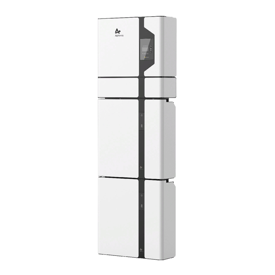
Page 13: System Appearance
Your Smart Energy Introduction 1.6 System Appearance Figure 4 Storion-SMILE5 Delivery Scope Object Description Hybrid Inverter EMS Display Screen Cable Box (connected to Inverter) SMILE5-BAT (Battery 1) SMILE5-BAT (Battery 2) ___________________________________________________________________ Alpha ESS Co., Ltd. Page 11... - Page 14 External Device Control Interface USB Debug Communication Port Relay Inverter Debug Communication DRMS Power Dispatching Port Meter Meter Communication Port Net Wire Connection Port External Expansion Port Battery Communication Port CAN/RS485 Or External Dispatching Port ___________________________________________________________________ Alpha ESS Co., Ltd. Page 12...
-
Page 15: Liability Limitation
The maintenance procedures relating to the product have not been followed to an acceptable standard; • Force majeure (violent or stormy weather, lightning, overvoltage, fire etc.); • Damages caused by any external factors. ___________________________________________________________________ Alpha ESS Co., Ltd. Page 13... -
Page 16: Installation
Your Smart Energy Installation 2. Installation This Manual introduces the basic steps how to install and set up AlphaESS Storion-SMILE5. SMILE5-BAT is a sealed component with no access to battery terminals or cell components within the module. SMILE5-BAT contains a Bi-pole DC isolator, which conforms to IEC 60947. It has been operated in all... - Page 17 900 mm above the SMILE5; and (iii) 600 mm before the SMILE5. If the distance between the Storion-SMILE5 and the ceiling or any object above the system is less than 900 mm, the ceiling or structural surface above the system must be made of non- combustible material within a radius of 600 mm around the system.
-
Page 18: Installation
(each battery has such a cover on the left and right sides of the case.). Set the covers aside and close the case. NOTE: The front cover of the battery should not be opened more than 90° ___________________________________________________________________ Alpha ESS Co., Ltd. Page 16... - Page 19 (with 2 batteries you must remove the cover of one battery, with 3 batteries the covers of 2 batteries, with 4 batteries the covers of 3 batteries etc.) For the new version battery please connect the power cables directly. ___________________________________________________________________ Alpha ESS Co., Ltd. Page 17...
- Page 20 Close the battery front cover and connect the power cable at the top, which Step 4: are included in the parts list of SMILE5-BAT M5*10 Screws Figure 15 Assemble Battery Mounting Panel Step 5: Assemble the battery mounting panel on the battery. ___________________________________________________________________ Alpha ESS Co., Ltd. Page 18...
- Page 21 3° . M6 Gasket φ8*60 Figure 17 Battery Installation – Mounting on the Wall Step 7: Remove the debris baffle and secure the battery to the wall with screws and ___________________________________________________________________ Alpha ESS Co., Ltd. Page 19...
- Page 22 Figure 19 Wall Bracket Installation Step 9: Take out the inverter position plate and the wall bracket and connect them using the M4 nuts as shown above. Check carefully if everything is tight. ___________________________________________________________________ Alpha ESS Co., Ltd. Page 20...
- Page 23 Remove the wall bracket and drill holes at the marked position on the wall. (Drill φ12mm) Figure 21 Wall Bracket Installation - Install the metal expansion bolts Step 11: Knock the metal expansion tube bolts into the wall holes and unscrew the hexagonal bolts. ___________________________________________________________________ Alpha ESS Co., Ltd. Page 21...
- Page 24 Strip the insulation sheath of the three-core AC cable for about 35mm. Cut L and N cable for 5mm. Strip L, N and PE cables 6- 7mm for respectively to make sure X-length is 5mm longer than Y- length of L/ N cable. ___________________________________________________________________ Alpha ESS Co., Ltd. Page 22...
- Page 25 Crimp the wire according to the position shown, tighten the screw torque0.8± 0.1N·m. Line male Insert the cables into the corresponding Pin holes and tighten the screws with the screwdrivers. Female Male c. The plastic core is screwed into the body ___________________________________________________________________ Alpha ESS Co., Ltd. Page 23...
- Page 26 NOTE: In Australia and New Zealand, the neutral of backup and grid circuit should be externally connected on the neutral bar. NOTE: No external earthing required. After the PE line of AC cables has been grounded, the whole inverter including the case will be grounded. ___________________________________________________________________ Alpha ESS Co., Ltd. Page 24...
- Page 27 :Remove the WiFi panel on the top and install the WiFi module (tool: Step 14 T20 screwdriver, torque: 1.6Nm). Please refer to section 错误!未找到引用源。 configuration network instructions. Figure 25 Communication interface of the inverter ___________________________________________________________________ Alpha ESS Co., Ltd. Page 25...
- Page 28 Figure 26 Network Cable Type B NOTE: The communication cable is in type B, see Figure 26. Leave the power cables and communication cables hang on the outside. Leave the device aside. ___________________________________________________________________ Alpha ESS Co., Ltd. Page 26...
- Page 29 The system and the Demand Response Enabling Device (DRED) must be connected in the same network. Only DRM0 is available for SMILE5 system. RJ45 Pin MODE View DRM4 DRM5 DRM1 DRM2 DRM3 DRM0 Ref Gen ___________________________________________________________________ Alpha ESS Co., Ltd. Page 27...
- Page 30 According to AS/NZS 5033, the system must be grounding, including the inverter and battery part. Otherwise, the installer will receive a mail like this (This function will be actived automatically once the system is commission.): 1. Grounding of Grid & Backup: ___________________________________________________________________ Alpha ESS Co., Ltd. Page 28...
- Page 31 Your Smart Energy Installation Earthing 2. Grounding of inverter shell: 3. Grounding of battery shell: ___________________________________________________________________ Alpha ESS Co., Ltd. Page 29...
- Page 32 Step 12: Connect the power cables of the bottom battery from Step 4 to the side terminals of the top battery. Make sure that red connects to red and black connects to black. ___________________________________________________________________ Alpha ESS Co., Ltd. Page 30...
- Page 33 Step 13: Connect the power cable of the top battery from Step 4 to the terminals of the cable box. Make sure that red connects to red and black connects to black. Earthing Point Figure 31 Earthing Point of Battery ___________________________________________________________________ Alpha ESS Co., Ltd. Page 31...
- Page 34 Step 20: Close the battery covers and connect the PV-MC4 connectors to the system (connection on both sides). Also, connect all AC cables, the meter communications cable METER, and the Ethernet cable LAN. Then close the cable box cover. The installation is now complete. ___________________________________________________________________ Alpha ESS Co., Ltd. Page 32...
- Page 35 The inverter includes an integrated residual current device (RCD) which trips at a re- sidual current of 30 mA (Type A). 2.2.7 Single Line Diagram The single line diagrams of DC-, AC- and Hybrid-coupled system are as below: ___________________________________________________________________ Alpha ESS Co., Ltd. Page 33...
- Page 36 Your Smart Energy Installation Figure 34 DC-coupled system Figure 35 AC-coupled system ___________________________________________________________________ Alpha ESS Co., Ltd. Page 34...
-
Page 37: Power Meter Wiring
2.3 Power Meter Wiring The electricity meter should be mounted and connected at the grid transition point (feed-in point) so that it can measure the grid reference and feed-in power. Alpha ESS currently provides 4 different power meter solutions: ➢... - Page 38 For AC/Hybrid system, there are two meter needed: Option 1: with Meter Plug Option 2: without Meter Plug Figure 39 Two Meter Connect, with Meter Plug Figure 40 Two Meter Connect, without Meter Plug 2.3.2 Meter ADL-3000 (If Applicable) ___________________________________________________________________ Alpha ESS Co., Ltd. Page 36...
- Page 39 NOTE: Connect the power meter (PIN 7, 8) to the meter port of the cable box (PIN 3, 6) using the RJ45 cable. ADL-3000 single-phase connection (without CT, with meter plug), if applicable: LOAD Figure 42 ADL-3000 single-phase Connect (without CT, with Meter plug) ___________________________________________________________________ Alpha ESS Co., Ltd. Page 37...
- Page 40 NOTE: Connect the power meter (PIN 7, 8) to the meter port of the cable box (PIN 3, 6) using the RJ45 cable. ADL-3000 single-phase connection (with CT, meter plug), if applicable: LOAD Figure 44 ADL-3000 single-phase Connect (with CT, with Meter plug) ___________________________________________________________________ Alpha ESS Co., Ltd. Page 38...
- Page 41 NOTE: Connect the power meter (PIN 7, 8) to the meter port of the cable box (PIN 3, 6) using the RJ45 cable. ADL-3000 three-phase connection (without CT, with meter plug), if applicable: Figure 46 ADL-3000 three-phase Connect (without CT, with Meter plug) ___________________________________________________________________ Alpha ESS Co., Ltd. Page 39...
- Page 42 Figure 48 ADL-3000 three-phase Connect (with CT, with Meter plug) NOTE: To connect the current transformer, connect S1 to L1 and S2 to L1’. For AC-/ Hybrid-system, there are two meter needed: Option 1: with Meter Plug Option 2: without Meter Plug ___________________________________________________________________ Alpha ESS Co., Ltd. Page 40...
- Page 43 CT should point away from the PV inverter to the energy storage system. 2.3.3 ACR10R Meter (if applicable) 2.3.3.1 ACR10R single-phase connection Grid CT Grid Meter Figure 51 ACR10R single-phase connection (if applicable) ___________________________________________________________________ Alpha ESS Co., Ltd. Page 41...
- Page 44 If the ACR10R meter is used as a PV meter in hybrid system, the direction of arrow in CT should point away from the PV inverter to the energy storage system. 2.3.4 Meter setting ___________________________________________________________________ Alpha ESS Co., Ltd. Page 42...
- Page 45 Step 5: Click the “Enter” button to get back to Step 6: Click the “Shift” button to save the the menu interface. Then click the “Shift” button setting. 5 times to enter the save interface. ___________________________________________________________________ Alpha ESS Co., Ltd. Page 43...
- Page 46 The Grid meter (DC, AC and Hybrid system) address is set to 001, the PV meter (AC and Hybrid system) address is set to 002. ___________________________________________________________________ Alpha ESS Co., Ltd. Page 44...
- Page 47 Step 11: Click the "Enter" button and the setting ends. 2.3.5.3 ACR10R There are 5 buttons on the meter's front: 1. Enter key 2. Arrow to the right 3. Up arrow 4. SET button 5. FN key (no function) ___________________________________________________________________ Alpha ESS Co., Ltd. Page 45...
- Page 48 When the meter is used as Grid meter (DC, AC/Hybrid system), the address is set to “005”. When it is used as the PV meter (AC/Hybrid system), the address is set to “006”. The baud rate is set to 9600. ___________________________________________________________________ Alpha ESS Co., Ltd. Page 46...
-
Page 49: System Operation
Press the power button on all the batteries, till the lights turn off. Step 2: Open cable box outer shell, open the battery switch cover and turn off the battery switch. Step 3: Turn off the external grid switch. ___________________________________________________________________ Alpha ESS Co., Ltd. Page 47... -
Page 50: Emergency Procedure
Novec 1230, the FM-200 or a dioxin extinguisher. If the fire is not from a battery, normal ABC fire extinguishers can be used for extinguishing. ___________________________________________________________________ Alpha ESS Co., Ltd. Page 48... -
Page 51: Ems Introduction And Set Up
Indicator LED Green: The inverter is in normal state. Green: The inverter is in communication. Return Button: Escape from current interface or function. Button Function Up button: Move cursor to upside or increase value. ___________________________________________________________________ Alpha ESS Co., Ltd. Page 49... -
Page 52: Introduction
Battery, Grid, UPS and Comm .These display the relevant information about the current physical or communication interface respectively. Grid interface displays the real-time information on the utility grid side: voltage U, current I, frequency F, P MeterAC MeterDC ___________________________________________________________________ Alpha ESS Co., Ltd. Page 50... - Page 53 MeterDC. 4.2.3 History History menu contains seven sub-menus: Grid Consumption, INV Gen., BAT Gen., PV Gen., Grid Charge, PV Charge, Error Logs Grid Consumption interface displays today’s or total load consumption from grid ___________________________________________________________________ Alpha ESS Co., Ltd. Page 51...
- Page 54 PV Charge interface displays today’s or total electricity quantity battery charging from the PV- panels. Error Logs interface displays the 10 latest fault records of this device, including the name of the fault and time of error. ___________________________________________________________________ Alpha ESS Co., Ltd. Page 52...
- Page 55 Step 1: Click setting and enter the password. The installation's password is a four-digit password and the installer can get the password from Alpha ESS in different pathway. After enter the password, you can enter into the main Setting interface (administrator permissions).
- Page 56 Step 12: If you want to use force charge, sett Step 13: Set the charge and discharge time. Enable here. Step 14: Set the UPS Reserve SOC, it means how much battery energy to keep for UPS function. ___________________________________________________________________ Alpha ESS Co., Ltd. Page 54...
- Page 57 MAC Address: display MAC Address. Step 20: Click Language to set language Step 21: Make sure all the following number is correct. 4.2.4.2 Additional Function Setting If you use Backup box, please set as below: ___________________________________________________________________ Alpha ESS Co., Ltd. Page 55...
- Page 58 Step 3: Please choose “Phase” as L1 (master) mode” and press enter. and press enter. Step 5: please repeat Step 1 to 4 to set the other device as L2 (slave) L3 (slave). ___________________________________________________________________ Alpha ESS Co., Ltd. Page 56...
-
Page 59: Commissioning
1.Android device users can download the APP through major Android application markets such as Google Play. 2.IOS device users can search for “AlphaESS” in AppStore and download the APP. AlphaESS-APP of Functions for Installer Account Overview ___________________________________________________________________ Alpha ESS Co., Ltd. Page 57... -
Page 60: Wifi Module Setting (Optional)
Step 1: Open AlphaESS APP, click Step 2: After that please check the “Wi-Fi Configuration” button and whether your mobile phone has enter the WiFi configuration interface. connected to the system’s hotspot. ___________________________________________________________________ Alpha ESS Co., Ltd. Page 58... -
Page 61: Create A New Plant
WiFi configuration step and directly set the system parameters. Note: the system will not be able to connect to the Internet without WiFi configuration. 5.4 Create a New Plant ___________________________________________________________________ Alpha ESS Co., Ltd. Page 59... -
Page 62: Choose The Battery Model
Login the installer account and choose Storage System Maintenance> "Install new system" to register a new system at Alpha ESS. The installer will be asked to input corresponding information as the picture shown below when he starts commissioning a new site, including the SN, Check Code, Liscense No. And so on. -
Page 63: Basic Configuration
NOTE: Only the installer and administrator will have the authority to select the safety country and regional option. The safety country and regional option will be locked after commissioning unless sending mail to the staff of Alpha ESS. NOTE: AS4777.2 means the latest standard AS/NZS 4777.2:2020. -
Page 64: Check After Commissioning
Check if wire connections are loose. ➢ Check if cables are aged/damaged. ➢ Check if cable insulating ribbon drops. ➢ Check if cable terminal screw loose, any overheat sign. ➢ Check if ground connection is well. ___________________________________________________________________ Alpha ESS Co., Ltd. Page 62... -
Page 65: Notes
Check whether the management system of the system equipment, monitoring system and other related equipment are invalid or damaged. ➢ Check that the grounding of the equipment is good and the grounding resistance is less than 10 ohms. 6.2 Notes ___________________________________________________________________ Alpha ESS Co., Ltd. Page 63... -
Page 66: Trouble Shooting
Please check the communication order BMS_Lost and connectivity between BMS and EMS. UPS_Battery_Volt_L Please charge the battery. Please check whether the critical load of Backup_Overload the inverter exceeds the loading capacity of the inverter. ___________________________________________________________________ Alpha ESS Co., Ltd. Page 64... - Page 67 Mos DriverFeedback 2048 Please contact AlphaESS service center. Error It is forbidden to discharge the battery and 4096 wait for the battery to recover from under- Cell Under-voltage voltage. ___________________________________________________________________ Alpha ESS Co., Ltd. Page 65...
- Page 68 TzProtectFault the inverter. MainsLostFault Please contact AlphaESS service center. Please confirm whether grid GridVoltFault parameters conform to the system grid regulations. Please confirm whether grid GridFreqFault parameters conform to the system grid regulations. ___________________________________________________________________ Alpha ESS Co., Ltd. Page 66...
- Page 69 524288 InputConfigFault consistent with MPPT number settings. Please update the inverter firmware. 1048576 EepromFault If the problem has not been solved, please contact AlphaESS service center. 2097152 RelayFault Please update the inverter firmware. ___________________________________________________________________ Alpha ESS Co., Ltd. Page 67...
- Page 70 1073741824 Other_DeviceFault If the problem has not been solved, please contact AlphaESS service center. Please update the inverter firmware. 2147483648 UpsRelayFault If the problem has not been solved, please contact AlphaESS service center. ___________________________________________________________________ Alpha ESS Co., Ltd. Page 68...
-
Page 71: Specification
5 kW / 5 kVA Phase Single phase Rated Grid Voltage L/N/PE,230 V Grid Voltage Range 180 ~ 270 V Rated Grid Frequency 50 / 60 Hz Rating Grid Output Current 21.7 A ___________________________________________________________________ Alpha ESS Co., Ltd. Page 69... - Page 72 Max. Operation Altitude 2000 m Battery pack (SMILE5-BAT) Battery Type LFP (LiFePO4) Weight 65 kg Energy Capacity 5.7 kWh Usable Capacity 5.5 kWh Nominal Voltage 51.2 V Operating Voltage Range 48 ~ 57.6 V ___________________________________________________________________ Alpha ESS Co., Ltd. Page 70...
-
Page 73: Appendix 1: Safety Country Code
Germany AS4777.2 Australia Regional standards C10/C11 Belgium TOR Erzeuger Austria CEI 0-21 Italy NRS 097-2-1 South Africa G98/G99 Britain 50Hz default 50Hz grid For 50Hz grid region G98/G99-IE Ireland EN50549 NC Rfg Poland ___________________________________________________________________ Alpha ESS Co., Ltd. Page 71... -
Page 74: Appendix 2: Regional Application Standard
⚫ Choose the correspond Regional application Standard, the power quality modes Volt-var and Volt-Watt will running automatically. (Only for Australia) ⚫ All the value of setting point is according to AS NZ 4777.2-2020 and loacl electricty company. ___________________________________________________________________ Alpha ESS Co., Ltd. Page 72... -
Page 75: Appendix 3: System Connection Diagrams
Example for grid systems without special requirements on electrical wiring connection. (The back-up PE line and earthing bar must be grounded properly and effectively. Otherwise the back-up function may be abnormal when the grid fails.) ___________________________________________________________________ Alpha ESS Co., Ltd. Page 73...
Need help?
Do you have a question about the Storion-SMILE5 and is the answer not in the manual?
Questions and answers