Alpha ESS Storion-SMILE5 Installation, Operation & Maintenance Manual
Energy storage system ess
Hide thumbs
Also See for Storion-SMILE5:
- Installation, operation & maintenance manual (75 pages) ,
- Installation manual (40 pages) ,
- Installation, operation & maintenance manual (71 pages)

Related Manuals for Alpha ESS Storion-SMILE5


Summary of Contents for Alpha ESS Storion-SMILE5
- Page 1 Installation, Operation & Maintenance Manual Energy Storage System (ESS) Storion-SMILE5 V1.79...
-
Page 2: Imprint
Web: www.alpha-ess.com Add: JiuHua Road 888, High-Tech Industrial Development Zone 226300 Nantong City, Jiangsu Province Australia Alpha ESS Australia Pty. Ltd. Tel.: +61 1300 968 933 E-mail: australia@alpha-ess.com Web: www.alpha-ess.com.au Add: Suite 1, Level 1, 530 Botany Road, Alexandria, NSW, 2015 Italy Alpha ESS Italy S.r.l. -
Page 3: Copyright Statement
Copyright Statement Copyright Statement This manual is under the copyright of Alpha ESS Co., Ltd. with all rights reserved. Please keep the manual properly and operate in strict accordance with all safety and operating instructions in this manual. Please do not operate the system without read- ing through the manual. -
Page 4: Table Of Contents
2.3.1 Meter ADL-3000 (If Applicable) .................29 2.3.2 Meter SM60A (If Applicable) ..................32 2.3.3 Backup Box (If Applicable) ..................33 System Operation ....................35 3.1 Switch on ....................... 35 3.2 Switch off ....................... 37 ___________________________________________________________________ Alpha ESS Co., Ltd. Page III of 52... - Page 5 Online Monitoring ....................46 5.1 Register ......................46 5.2 Registering License ..................47 Annex........................48 6.1 Datasheet – AlphaESS Storion-SMILE5 ............. 48 Routine Maintenance..................49 7.1 Maintenance Plan ..................49 7.1.1 Operating Environment ..................... 49 7.1.2 Equipment Cleaning ....................49 7.1.3 Cable, Terminal and Equipment Inspection ..............
-
Page 6: Introduction
Your Smart Energy Introduction Introduction 1.1 System Introduction AlphaESS Storion-SMILE5 (incl. SMILE5-BAT and SMILE-INV) can be applied in DC- coupled systems (mostly new installation), AC-coupled systems (mostly retrofit) and Hybrid-coupled systems (mostly retrofit, and PV capacity-increase), as the following scheme:... -
Page 7: Protection Of Warning Sign
It indicates a hazardous situation which, if not avoided, could result in death or serious injury! Danger of high voltage and electric shock! Storion-SMILE5 will be touchable or operable after minimum 5 minutes of being turned off or totally disconnected, in case of any electrical shock or injury. -
Page 8: Operation After Power Failure
DC connectors from the system under load, an electric arc may occur leading to electric shock and burns. Do not touch uninsulated cable ends. Do not touch the DC conductors. ___________________________________________________________________ Alpha ESS Co., Ltd. Page 7 of 52... - Page 9 Do not move the system when it is already connected with battery modules. Secure the system to prevent tipping with restraining straps in your vehicle. The transportation of AlphaESS Storion-SMILE5 must be made by the manufacturer or an instructed personal. These instructions shall be recorded and repeated.
-
Page 10: Parts List
(1x SM 60A or 1x ADL 3000) Manual Manual SMILE5-BAT 6x M8*60 6x M5*10 6x M4*10 2x Mounting Panel 2x Power Cable 6x M6 Gasket 1x User Manual Battery Communication Cable (1 black, 1 red) ___________________________________________________________________ Alpha ESS Co., Ltd. Page 9 of 52... -
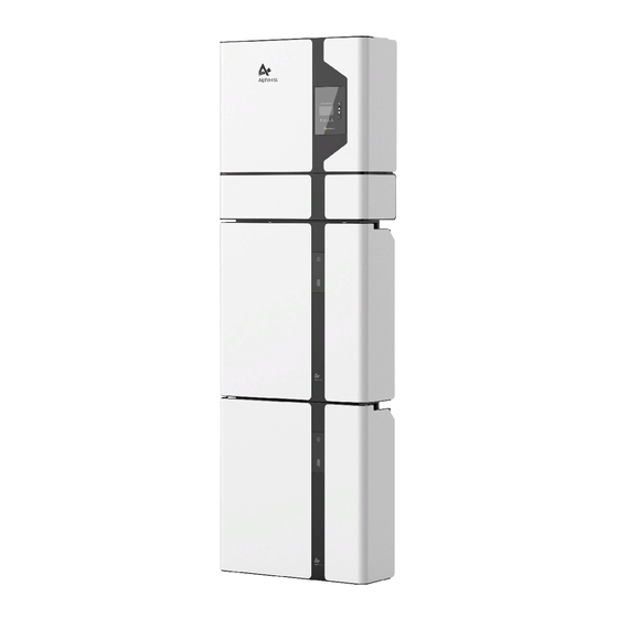
Page 11: System Appearance
Your Smart Energy Introduction 1.5 System Appearance Figure 2 Storion-SMILE5 Delivery Scope Object Description Hybrid Inverter with Cable Box Display Screen Cable Box Part of Inverter SMILE5-BAT (Battery 1) SMILE5-BAT (Battery 2) ___________________________________________________________________ Alpha ESS Co., Ltd. Page 10 of 52... - Page 12 Figure 4 Inverter without CableBox Covers - Rear Front View View Figure 5 Cable Box Part without Covers – Front View Item Item Description Description Battery Switch PV Switch GRID Back up GRID Switch Backup Switch ___________________________________________________________________ Alpha ESS Co., Ltd. Page 11 of 52...
- Page 13 Figure 6 Cable Box Part without Covers - Rear View Object Item Description Description RS485 Connection for Inverter communication port METER(2) INV(2) Meter LAN1(2) Ethernet Connection DRM(2) Debug port Battery communication Battery out line BMS(2) BAT(1) port ___________________________________________________________________ Alpha ESS Co., Ltd. Page 12 of 52...
- Page 14 Your Smart Energy Introduction ___________________________________________________________________ Alpha ESS Co., Ltd. Page 13 of 52...
-
Page 15: Liability Limitation
The maintenance procedures relating to the product have not been followed to an acceptable standard; Force majeure (violent or stormy weather, lightning, overvoltage, fire etc.); Damages caused by any external factors. ___________________________________________________________________ Alpha ESS Co., Ltd. Page 14 of 52... -
Page 16: Installation
earthquake areas –additional security measures are required here; sites that are higher than 3000 meters above the sea level; sites with explosive atmosphere; sites with direct sunlight; sites with extreme change of ambient temperature; ___________________________________________________________________ Alpha ESS Co., Ltd. Page 15 of 52... -
Page 17: Restricted Locations
600 mm beyond the vertical sides of the SMILE5; (ii) 1200 mm above the SMILE5; and (iii) to the extent of the bottom of the SMILE5. Please refer to Figure 7. ___________________________________________________________________ Alpha ESS Co., Ltd. Page 16 of 52... -
Page 18: Installation
SMILE5 shall be mounted with the highest point no greater than 2.2 m above the floor or platform. 2.2 Installation Figure 8 Unpacking the inverter and battery Step 1: Remove the battery and inverter from the packaging box. ___________________________________________________________________ Alpha ESS Co., Ltd. Page 17 of 52... - Page 19 Step 2: Open battery housing case and remove communication wiring baffle at the left side. Battery Cover Positive Connector Anti-explosion Valve Negative Connector Figure 11 Disassembly Diagram of Battery Top Cover Step 3: Remove the top cover of the battery. ___________________________________________________________________ Alpha ESS Co., Ltd. Page 18 of 52...
- Page 20 Step 4: Close the battery front cover and connect the power cable at the top. M5*10 Screws Figure 13 Assemble Battery Mounting Panel Step 5: Assemble the battery mounting panel on the battery. ___________________________________________________________________ Alpha ESS Co., Ltd. Page 19 of 52...
- Page 21 Figure 14 shows). The ground upon which the battery will be placed on must be less than 3 degree to the horizontal level. M6 Gasket M8*60 ___________________________________________________________________ Alpha ESS Co., Ltd. Page 20 of 52...
- Page 22 Step 8: Follow Step6 and Step7 to install the second battery. Figure 17 Inverter Mounting Panel Installation Step 9: Install the inverter mounting panel and mounting bracket with M4 nuts as shown above. ___________________________________________________________________ Alpha ESS Co., Ltd. Page 21 of 52...
- Page 23 Figure 18 Inverter Installation - Inverter Mounting Panel Step 10: Drill holes on the wall with impact drill first then install and position inverter mounting panel. Battery installation is now completed. ___________________________________________________________________ Alpha ESS Co., Ltd. Page 22 of 52...
- Page 24 NOTE: The communication cables outside are not equipped with RJ45 connectors. The current of the breaker that connects the inverter must be more than 25A. Communication Baffle Figure 20 Inverter with pre-wired Cables ___________________________________________________________________ Alpha ESS Co., Ltd. Page 23 of 52...
- Page 25 Figure 22 Inverter Installation on the Wall Step 13: Hang the inverter onto the mounting panels, adjust the entire system and ensure that the battery and the inverter have been securely hung onto the panels and brackets. ___________________________________________________________________ Alpha ESS Co., Ltd. Page 24 of 52...
- Page 26 After all above connections done then lock all communication baffles. (If you want to add more the batteries, the new batteries have to been connected first) Figure 23 Wiring the Battry Power Cable ___________________________________________________________________ Alpha ESS Co., Ltd. Page 25 of 52...
- Page 27 Figure 24 Wiring the Power Cable of the Cable Box Step 16: Connect the power cable from Step 4 to the terminals of cable box. Make sure that red connects to red and black connects to black. ___________________________________________________________________ Alpha ESS Co., Ltd. Page 26 of 52...
- Page 28 (both sides). At the same time connect all the AC, meter communication cable, ethernet communication cable and then close the cable box cover. The installation is now complete. NOTE: the RCD unit must be installed. A 100mA RCD device is recommended. ___________________________________________________________________ Alpha ESS Co., Ltd. Page 27 of 52...
- Page 29 Figure 27 Increase the Battery Modules NOTE: when adding on battery modules, please install only by side. You can add up to 6 extra batteries with each two in a string. ___________________________________________________________________ Alpha ESS Co., Ltd. Page 28 of 52...
-
Page 30: Power Meter
NOTE: Meter 7, 8 connect the RJ45 3, 6, then RJ45 connect the cable box/super cable box. ADL-3000 single-phase connect (without CT, with meter plug), if applicable: LOAD Figure 29 ADL-3000 single-phase Connect (without CT, with Meter plug) ___________________________________________________________________ Alpha ESS Co., Ltd. Page 29 of 52... - Page 31 NOTE: Meter 7, 8 connect the RJ45 3, 6, then RJ45 connect the cable box/super cable box. ADL-3000 single-phase connect (with CT, meter plug), if applicable: LOAD Figure 31 ADL-3000 single-phase Connect (with CT, with Meter plug) ___________________________________________________________________ Alpha ESS Co., Ltd. Page 30 of 52...
- Page 32 NOTE: Meter 7, 8 connect the RJ45 3, 6, then RJ45 connect the cable box/super cable box. ADL-3000 three-phase connect (without CT, with meter plug), if applicable: Figure 33 ADL-3000 three-phase Connect (without CT, with Meter plug) ___________________________________________________________________ Alpha ESS Co., Ltd. Page 31 of 52...
-
Page 33: Meter Sm60A (If Applicable)
Option 1: with Meter Plug Option 2: without Meter Plug Figure 37 Two Meter Connect, without Meter Plug Figure 36 Two Meter Connect, with Meter Plug 2.3.2 Meter SM60A (If Applicable) ___________________________________________________________________ Alpha ESS Co., Ltd. Page 32 of 52... -
Page 34: Backup Box (If Applicable)
Option 2: without Meter Plug Figure 40 Two Meter Connect, with Meter Figure 41 Two Meter Connect, without Meter Plug Plug 2.3.3 Backup Box (If Applicable) Backup Box Connect to SMILE5 (single-phase grid in house): ___________________________________________________________________ Alpha ESS Co., Ltd. Page 33 of 52... - Page 35 Figure 44 ACR meter three-phase connection (if applicable) 2.3.4.3 ACR Meter setting Step 1: This is the initial interface of the Step 2: Click the "SETUP" button; meter, click the “Set” button; ___________________________________________________________________ Alpha ESS Co., Ltd. Page 34 of 52...
-
Page 36: System Operation
Step 6:After the meter is set, you need to activate the CT ratio on the display; System Operation 3.1 Switch on System shall be turned on in the correct sequence to avoid any damage. ___________________________________________________________________ Alpha ESS Co., Ltd. Page 35 of 52... - Page 37 Your Smart Energy System Operation Step 1: Open cable box outer Step 2: Unlock then open Cable box inner shell. cover. Cable box locker can be opened without tools. ___________________________________________________________________ Alpha ESS Co., Ltd. Page 36 of 52...
-
Page 38: Switch Off
Press button 1 on all the batteries, till the lights off. Step 3: Turn off the Battery switch. Step 4: Turn off the GRID switch. Step 5: If backup load is applied, turn off the Backup switch. ___________________________________________________________________ Alpha ESS Co., Ltd. Page 37 of 52... - Page 39 Step 6: Turn off the PV switch on the cable box. Step 7: Close the inner cover and outer shell of Cable box. More information can be found in SMILE5-BAT user manual. ___________________________________________________________________ Alpha ESS Co., Ltd. Page 38 of 52...
-
Page 40: Ems Introduction And Set Up
Button Function ENT Button: Confirm the selection. Up button: Move cursor to upside or increase value. Display the information of the inverter in LCD Screen this LCD screen. ___________________________________________________________________ Alpha ESS Co., Ltd. Page 39 of 52... -
Page 41: Introduction
Figure 45 Status Menu Grid interface displays the real-time information on the city electric side: voltage U, current I, frequency F, P MeterAC MeterDC Figure 46 Grid Interface ___________________________________________________________________ Alpha ESS Co., Ltd. Page 40 of 52... -
Page 42: History
Net, MeterGrid and MeterDC. Figure 53 Communication Interface 4.2.3 History History menu contains seven sub-menus: Grid Consumption, INV Gen., BAT Gen., PV Gen., Grid Charge, PV Charge, Error Logs Figure 54 History Menu ___________________________________________________________________ Alpha ESS Co., Ltd. Page 41 of 52... - Page 43 PV- panels. Figure 58 PV Gen. Interface Grid Charge interface displays today’s or total electricity quantity battery charging from the grid. Figure 59 Grid Charge. Interface ___________________________________________________________________ Alpha ESS Co., Ltd. Page 42 of 52...
-
Page 44: Setting
Step 1: Click setting and enter the password. The installation's password is four digits password: 1111, after four-digits password is correctly input, you can enter into the main Setting interface (administrator permissions). Figure 63 Password Interface ___________________________________________________________________ Alpha ESS Co., Ltd. Page 43 of 52... - Page 45 Figure 71 Max. Feed in rate Setting Interface Step 8: Click the Grid Function to set up Step 9: Set the Max. Feed in rate value. relevant parameters about the grid ___________________________________________________________________ Alpha ESS Co., Ltd. Page 44 of 52...
- Page 46 If you want to set up the IP address manually, please choose manual mode. NOTE: It is needed to set the following 3 parameters for manual mode: IP Address: IP address; ___________________________________________________________________ Alpha ESS Co., Ltd. Page 45 of 52...
-
Page 47: Online Monitoring
So please use the following steps: Open the portal: www.alphaess.com. Please fill in “Username”, “Password” and click “Login”, if you have registered. If not, please register following these steps Figure 81 Monitoring Login Interface ___________________________________________________________________ Alpha ESS Co., Ltd. Page 46 of 52... -
Page 48: Registering License
Online Monitoring Webserver installation Manual. Figure 82 Register Interface 5.2 Registering License Figure 83 System Registering Interface Input S/N, Check Code, License No., Date, Name, and Contact No. to complete the registering process. ___________________________________________________________________ Alpha ESS Co., Ltd. Page 47 of 52... -
Page 49: Annex
Your Smart Energy Annex Annex 6.1 Datasheet – AlphaESS Storion-SMILE5 System Model Storion-SMILE5 Battery SMILE5-BAT 5.7 / 11.5 / 17.2 /…/ 34.4 kWh (90% DoD Recommended) Installed Capacity Usable Capacity 5.5 / 11.0 / 16.5 / ../ 33.0 kWh *... -
Page 50: Routine Maintenance
(Every six months to one year) Check if the cable connection is loose. Check whether the cable is aging or damaged. Check whether the cable tie of the cable has fallen off. ___________________________________________________________________ Alpha ESS Co., Ltd. Page 49 of 52... -
Page 51: Notes
(that is, the batteries has not been charged for two weeks or longer) for a long time, in case of over discharge. Please contact us in time if there are any conditions that could not be explained in the ymanual. ___________________________________________________________________ Alpha ESS Co., Ltd. Page 50 of 52...
Need help?
Do you have a question about the Storion-SMILE5 and is the answer not in the manual?
Questions and answers