Alpha ESS Storion-SMILE5 Installation Manual
Energy storage system
Hide thumbs
Also See for Storion-SMILE5:
- Installation, operation & maintenance manual (75 pages) ,
- Installation manual (32 pages) ,
- Installation, operation & maintenance manual (71 pages)
Table of Contents
Advertisement
Advertisement
Table of Contents

Related Manuals for Alpha ESS Storion-SMILE5


Summary of Contents for Alpha ESS Storion-SMILE5
- Page 1 Installation Manual Energy Storage System (ESS) Storion-SMILE5 V1.71...
- Page 2 Web: www.alpha-ess.com Add: JiuHua Road 888, High-Tech Industrial Development Zone 226300 Nantong City, Jiangsu Province Australia Alpha ESS Australia Pty. Ltd. Tel.: +61 1300 968 933 E-mail: australia@alpha-ess.com Web: www.alpha-ess.com.au Add: Suite 2, Level 1, 530 Botany Road, Alexandria, NSW, 2015 Sep.
-
Page 3: Copyright Statement
Your Smart Energy Copyright Statement This manual is under the copyright of Alpha ESS Co., Ltd. with all rights reserved. Please keep the manual properly and operate in strict accordance with all safety and operating instructions in this manual. Please do not operate the system without read- ing through the manual. -
Page 4: Table Of Contents
4.2.3 History ......................31 4.2.4 Setting ......................33 Online Monitoring ..................37 5.1 Register ....................37 5.2 Registering License ................38 Annex ......................39 6.1 Datasheet – AlphaESS Storion-SMILE5 ..........39 ___________________________________________________________________ Alpha ESS Co., Ltd. Page III of 40... -
Page 5: Introduction
Have the system installed and commissioned by qualified people with the appropriate skills only. Prior to performing any work on the inverter or the battery pack, disconnect the inverter from all voltage sources as described in this document. ___________________________________________________________________ Alpha ESS Co., Ltd. Page 4 of 40... - Page 6 Do not move the system when it is already connected with battery modules. Secure the system to prevent tipping with restraining straps in your vehicle. The transportation of AlphaESS Storion-SMILE5 must be made by the manufacturer or an instructed personal. These instructions shall be recorded and repeated.
-
Page 7: Parts List
(1x SM 60A or 1x ADL 3000) Manual Manual SMILE5-BAT 6x M8*60 6x M5*10 6x M4*10 2x Mounting Panel 2x Power Cable 6x M6 Gasket 1x User Manual Battery Communication Cable (1 black, 1 red) ___________________________________________________________________ Alpha ESS Co., Ltd. Page 6 of 40... -
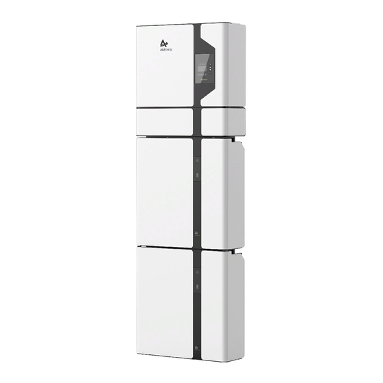
Page 8: System Appearance
Your Smart Energy 1.4 System Appearance Figure 2 Storion-SMILE5 Delivery Scope Object Description Hybrid Inverter with Cable Box Display Screen Cable Box Part of Inverter SMILE5-BAT (Battery 1) SMILE5-BAT (Battery 2) ___________________________________________________________________ Alpha ESS Co., Ltd. Page 7 of 40... - Page 9 Description BAT(1) Battery Switch PV Switch GRID Back up GRID Switch Backup Switch BAT(2) Inverter Debug Communication Battery Debug Communication USB Debug Communication Figure 6 Cable Box Part - Rear View ___________________________________________________________________ Alpha ESS Co., Ltd. Page 8 of 40...
-
Page 10: Liability Limitation
The maintenance procedures relating to the product have not been followed to an acceptable standard; Force majeure (violent or stormy weather, lightning, overvoltage, fire etc.); Damages caused by any external factors. ___________________________________________________________________ Alpha ESS Co., Ltd. Page 9 of 40... -
Page 11: Installation
Sites that are higher than 2000 meters above the sea level. Sites with explosive atmosphere. Sites with direct sunlight. Sites with extreme change of ambient temperature. Wet rooms. Sites with highly flammable materials or gases. ___________________________________________________________________ Alpha ESS Co., Ltd. Page 10 of 40... -
Page 12: Installation
Figure 10 Battery with Lid off – Side View Figure 9 Battery with Lid off - Front View Step 2: Open battery housing case and remove communication wiring baffle at the left side. ___________________________________________________________________ Alpha ESS Co., Ltd. Page 11 of 40... - Page 13 Step 4: Close the battery front cover and connect the power cable at the top. NOTE: if there is an “indoor” sign on the top cover, the battery can only be installed indoor. ___________________________________________________________________ Alpha ESS Co., Ltd. Page 12 of 40...
- Page 14 Figure 14 shows). The ground upon which the battery will be placed on must be less than 3 degree to the horizontal level. ___________________________________________________________________ Alpha ESS Co., Ltd. Page 13 of 40...
- Page 15 Step 7: Remove the debris baffle and secure the battery to the wall with screws. Figure 16 Battery Installation – Second Battery Installation Step 8: Follow Step6 and Step7 to install the second battery. ___________________________________________________________________ Alpha ESS Co., Ltd. Page 14 of 40...
- Page 16 Figure 18 Inverter Installation - Inverter Mounting Panel Step 10: Drill holes on the wall with impact drill first then install and position inverter mounting panel. Battery installation is now completed. ___________________________________________________________________ Alpha ESS Co., Ltd. Page 15 of 40...
- Page 17 Remove the screw to take off the back cover. Set the front and back covers of cable box aside. Power Cable Network Cable Access Figure 20 Communication and Power Cable Access ___________________________________________________________________ Alpha ESS Co., Ltd. Page 16 of 40...
- Page 18 RJ45 into BAT end inside of cable box and leave the outside end there for now). NOTE: the current of the breaker that connects the inverter must be more than 25A. Communication Baffle Figure 22 Inverter Wiring Completion Diagram ___________________________________________________________________ Alpha ESS Co., Ltd. Page 17 of 40...
- Page 19 Step 15: Hang the inverter onto the mounting panels, adjust the entire system and ensure that the battery and the inverter have been securely hung onto the panels and brackets. NOTE: Pay attention to the placing direction of the power and communication cables. ___________________________________________________________________ Alpha ESS Co., Ltd. Page 18 of 40...
- Page 20 Figure 26 Wiring the Battry Power Cable Step 17: Connect the batteries from Step4 to the terminals. Make sure that red connects to red and black connects to black. ___________________________________________________________________ Alpha ESS Co., Ltd. Page 19 of 40...
- Page 21 Figure 28 PV Wiring Step 19: Close the battery covers and connect the PV MC4 connectors as shown in the diagram (both sides). At the same time connect all the AC, meter ___________________________________________________________________ Alpha ESS Co., Ltd. Page 20 of 40...
- Page 22 NOTE: only the farthest battery from inverter need to set DIP. If you want to add more batteries, please install the extra ones by the side as shown below. Figure 30 Increase the Battery Modules ___________________________________________________________________ Alpha ESS Co., Ltd. Page 21 of 40...
-
Page 23: Power Meter
NOTE: Meter 7, 8 connect the RJ45 3, 6, then RJ45 connect the cable box/super cable box. ADL-3000 single-phase connect (without CT, with meter plug), if applicable: LOAD Figure 32 ADL-3000 single-phase Connect (without CT, with Meter plug) ___________________________________________________________________ Alpha ESS Co., Ltd. Page 22 of 40... - Page 24 LOAD Figure 34 ADL-3000 single-phase Connect (with CT, with Meter plug) ADL-3000 three-phase connect (without CT, without meter plug), if applicable: Figure 35 ADL-3000 three-phase Connect (without CT, without Meter plug) ___________________________________________________________________ Alpha ESS Co., Ltd. Page 23 of 40...
- Page 25 ADL-3000 three-phase connect (with CT, without meter plug), if applicable: Figure 37 ADL-3000 three-phase Connect (with CT, without Meter plug) NOTE: Meter 7, 8 connect the RJ45 3, 6, then RJ45 connect the cable box/super cable box. ___________________________________________________________________ Alpha ESS Co., Ltd. Page 24 of 40...
-
Page 26: Meter Sm60A (If Applicable)
Figure 39 Two Meter Connect, with Meter Figure 40 Two Meter Connect, without Meter Plug Plug 2.3.2 Meter SM60A (If Applicable) SM60A connect (with meter plug), if applicable: LOAD Figure 41 SM60A connect (with meter plug) ___________________________________________________________________ Alpha ESS Co., Ltd. Page 25 of 40... -
Page 27: Backup Box (If Applicable)
GRID_N BAK_L3 Storion-S5 PV-INV_N PV-INV meter LOAD_N ECO-ES5 AC_N SMILE5 GRID_PE BACK BAK_N PV-INV_PE Meter Port patch cable DSP_BackupBox Figure 45 Backup Box Connect to SMILE5 (single phase grid in house) ___________________________________________________________________ Alpha ESS Co., Ltd. Page 26 of 40... -
Page 28: System Operation
Backup ports and turn on the Backup switch; if not, then keep the Backup switch off. NOTE: the Backup switch is only used when a backup load is applied. ___________________________________________________________________ Alpha ESS Co., Ltd. Page 27 of 40... -
Page 29: Switch Off
Step 6: Turn off the PV switch on the cable box. Step 7: Close the inner cover and outer shell of Cable box. More information can be found in SMILE5-BAT user manual. ___________________________________________________________________ Alpha ESS Co., Ltd. Page 28 of 40... -
Page 30: Ems Introduction And Set Up
Button Function ENT Button: Confirm the selection. Up button: Move cursor to upside or increase value. Display the information of the inverter in LCD Screen this LCD screen. ___________________________________________________________________ Alpha ESS Co., Ltd. Page 29 of 40... -
Page 31: Introduction
Figure 49 Status Menu Grid interface displays the real-time information on the city electric side: voltage U, current I, frequency F, P MeterAC MeterDC Figure 50 Grid Interface ___________________________________________________________________ Alpha ESS Co., Ltd. Page 30 of 40... -
Page 32: History
Net, MeterGrid and MeterDC. Figure 54 Communication Interface 4.2.3 History History menu contains seven sub-menus: Grid Consumption, INV Gen., BAT Gen., PV Gen., Grid Charge, PV Charge, Error Logs Figure 55 History Menu ___________________________________________________________________ Alpha ESS Co., Ltd. Page 31 of 40... - Page 33 PV- panels. Figure 59 PV Gen. Interface Grid Charge interface displays today’s or total electricity quantity battery charging from the grid. Figure 60 Grid Charge. Interface ___________________________________________________________________ Alpha ESS Co., Ltd. Page 32 of 40...
-
Page 34: Setting
(administrator permissions). Figure 63 Password Interface Figure 64 Setting Menu Figure 65 Function Interface Step 2: Click Function to enter function Step 3: Click Solar to set the Solar setting. relevant information. ___________________________________________________________________ Alpha ESS Co., Ltd. Page 33 of 40... - Page 35 Figure 73 Work Mode Setting Interface Step 10: Click Function-System Mode to Step 11: Click the mode then set up work set system mode: DC, AC, Hybrid. mode.(self-use or force time charge) ___________________________________________________________________ Alpha ESS Co., Ltd. Page 34 of 40...
- Page 36 If you want to set up the IP address manually, please choose manual mode. NOTE: It is needed to set the following 3 parameters for manual mode: IP Address: IP address; Subnet Mask: Subnet mask; Default Gateway: Default gateway; ___________________________________________________________________ Alpha ESS Co., Ltd. Page 35 of 40...
- Page 37 MAC Address: display MAC Address. Figure 80 Date&Time Setting Interface Figure 81 Date&Time Setting Interface Step 18: Click Language to set language Step 19: Make sure all the following number is correct. ___________________________________________________________________ Alpha ESS Co., Ltd. Page 36 of 40...
-
Page 38: Online Monitoring
In this form, all blanks marked with an asterisk must be filled out, you can choose End user or installer. More detailed information obtained in Online Monitoring Webserver installation Manual. Figure 74 Register Interface ___________________________________________________________________ Alpha ESS Co., Ltd. Page 37 of 40... -
Page 39: Registering License
Click Install new system to register the license No. Figure 74 Menu for Installer Figure 74 System Registering Interface Input S/N, Check Code, License No., Date, Name, and Contact No. to complete the registering process. ___________________________________________________________________ Alpha ESS Co., Ltd. Page 38 of 40... -
Page 40: Annex
Your Smart Energy Annex 6.1 Datasheet – AlphaESS Storion-SMILE5 System Model Storion-SMILE5 Battery SMILE5-BAT Installed Capacity 5.7/11.5/17.2/22.9/28.7/34.4 kWh Usable Capacity 5.2/10.3/15.5/20.6/25.8/30.9 kWh ≥6000 Cycle Life Product Warranty 5 Years Performance Warranty 10 Years Phase Single Phase Display Communication Ethernet Operating Temperature Range -10°C To 50°C*...
Need help?
Do you have a question about the Storion-SMILE5 and is the answer not in the manual?
Questions and answers