Alpha ESS Storion-SMILE5 Installation, Operation & Maintenance Manual
Energy storage system (ess)
Hide thumbs
Also See for Storion-SMILE5:
- Installation, operation & maintenance manual (75 pages) ,
- Installation manual (40 pages) ,
- Installation manual (32 pages)

Related Manuals for Alpha ESS Storion-SMILE5


Summary of Contents for Alpha ESS Storion-SMILE5
- Page 1 Installation, Operation & Maintenance Manual Energy Storage System (ESS) Storion-SMILE5 (AU)
-
Page 3: Imprint
Web: www.alpha-ess.com Add: JiuHua Road 888, High-Tech Industrial Development Zone 226300 Nantong City, Jiangsu Province Australia Alpha ESS Australia Pty. Ltd. Tel.: +61 1300 968 933 E-mail: australia@alpha-ess.com Web: www.alpha-ess.com.au Add: Suite 1, Level 1, 530 Botany Road, Alexandria, NSW, 2015 Italy Alpha ESS Italy S.r.l. -
Page 4: Copyright Statement
Introduction Copyright Statement This manual is under the copyright of Alpha ESS Co., Ltd. with all rights reserved. Please keep the manual properly and operate in strict accordance with all safety and operating instructions in this manual. Please do not operate the system before reading through the manual. -
Page 5: Table Of Contents
4.1 Function Description ......................44 4.2 Introduction ..........................45 Online Monitoring .......................... 52 5.1 System Setup in Monitoring ....................53 Routine Maintenance ........................54 6.1 Maintenance Plan ........................54 6.2 Notes ............................54 ___________________________________________________________________ Alpha ESS Co., Ltd. Page 3... -
Page 7: Introduction
Introduction Introduction 1.1 System Introduction AlphaESS Storion-SMILE5 (incl. SMILE5-BAT and SMILE-INV) can be applied in DC-coupled systems (mostly new installation), AC-coupled systems (mostly retrofit) and Hybrid-coupled systems (mostly retrofit, and PV capacity-increase), as the following schemes show: Figure 1 DC - Coupled Storage System – Scheme Figure 2 AC - Coupled Storage System –... -
Page 8: Safety Introduction
The warning signs contain important information for the system to operate safely, and it is strictly prohibited to torn or damage them. Ensure that the warning signs are always read-able and correct placed. The signs must be replaced immediately when damaged. ___________________________________________________________________ Alpha ESS Co., Ltd. Page 6... - Page 9 DC and / or AC side. Therefore, for safety reasons, it must be tested with a properly calibrated voltage tester before an installer works on the equipment.. ___________________________________________________________________ Alpha ESS Co., Ltd. Page 7...
-
Page 10: Battery Safety Datasheet
Have the system installed and commissioned by qualified people with the appropriate Ø skills only. Ø Prior to performing any work on the inverter or the battery pack, disconnect the inverter from all voltage sources as described in this document. ___________________________________________________________________ Alpha ESS Co., Ltd. Page 8... -
Page 11: Parts List
Ø Secure the system to prevent tipping with restraining straps in your vehicle. Ø The transportation of AlphaESS Storion-SMILE5 must be made by the manufacturer or an instructed personal. These instructions shall be recorded and repeated. Ø A certified ABC fire extinguisher with minimum capacity of 2kg must be carried along when transporting. - Page 12 Installation for grid and Manual ACR10R) Manual backup SMILE5-BAT 6xφ8*60 6x M5*10 6x M4*10 2x Mounting Panel 2x Power Cable 6x M6 Gasket 1x User Manual Battery Communication Cable (1 black, 1 red) ___________________________________________________________________ Alpha ESS Co., Ltd. Page 10...
-
Page 13: System Appearance
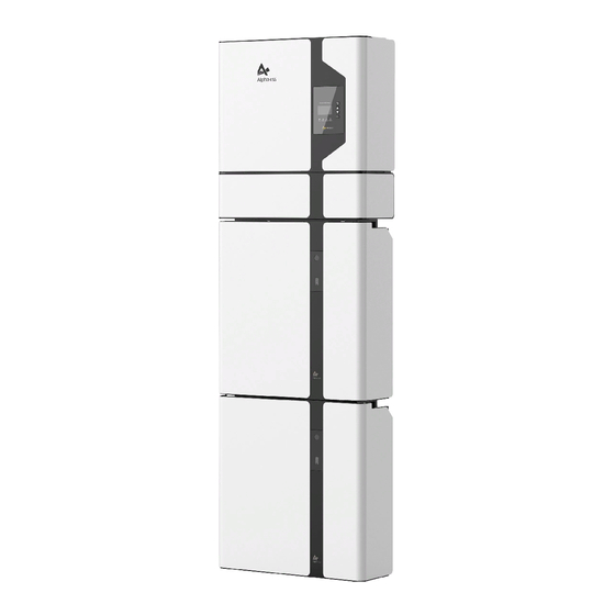
Your Smart Energy Introduction 1.6 System Appearance Figure 4 Storion-SMILE5 Delivery Scope Object Description Hybrid Inverter EMS Display Screen Cable Box (connected to Inverter) SMILE5-BAT (Battery 1) SMILE5-BAT (Battery 2) ___________________________________________________________________ Alpha ESS Co., Ltd. Page 11... - Page 14 External Device Control Interface USB Debug Communication Port Relay Inverter Debug Communication DRMS Power Dispatching Port Meter Meter Communication Port Net Wire Connection Port External Expansion Port Battery Communication Port Or External Dispatching Port ___________________________________________________________________ Alpha ESS Co., Ltd. Page 12...
-
Page 15: Liability Limitation
The maintenance procedures relating to the product have not been followed to an acceptable standard; • Force majeure (violent or stormy weather, lightning, overvoltage, fire etc.); • Damages caused by any external factors. ___________________________________________________________________ Alpha ESS Co., Ltd. Page 13... -
Page 16: Installation
Your Smart Energy Installation Installation This Manual introduces the basic steps how to install and set up AlphaESS Storion-SMILE5. SMILE5-BAT is a sealed component with no access to battery terminals or cell components within the module. SMILE5-BAT contains a Bi-pole DC isolator, which conforms to IEC 60947. It has been operated in all... -
Page 17: Installation
Figure 9 Limit Distance of Installation to Neighboring Objects 2.2 Installation Figure 10 Unpacking the inverter and battery Step 1: Remove the battery and inverter from the packaging box. ___________________________________________________________________ Alpha ESS Co., Ltd. Page 15... - Page 18 (with 2 batteries you must remove the cover of one battery, with 3 batteries the covers of 2 batteries, with 4 batteries the covers of 3 batteries etc.) For the new version battery please connect the power cables directly. ___________________________________________________________________ Alpha ESS Co., Ltd. Page 16...
- Page 19 Close the battery front cover and connect the power cable at the top, which Step 4: are included in the parts list of SMILE5-BAT M5*10 Screws Figure 15 Assemble Battery Mounting Panel Step 5: Assemble the battery mounting panel on the battery. ___________________________________________________________________ Alpha ESS Co., Ltd. Page 17...
- Page 20 3°. M6 Gasket φ8*60 Figure 17 Battery Installation – Mounting on the Wall Step 7: Remove the debris baffle and secure the battery to the wall with screws and ___________________________________________________________________ Alpha ESS Co., Ltd. Page 18...
- Page 21 Step 8: To assemble the second (and all other) battery, repeat steps 6 and 7, respectively. Figure 19 Inverter Mounting Panel Installation Step 9: Remove the inverter mounting plate and bracket and connect them using the M4 nuts as shown above. Check carefully if everything is tight. ___________________________________________________________________ Alpha ESS Co., Ltd. Page 19...
- Page 22 Strip the insulation sheath of the three-core AC cablefor about 35mm. Cut L and N cable for 5mm. Strip L, N and PE cables 6- 7mm for respectively to make sure X-length is 5mm longer than Y- length of L/ N cable. ___________________________________________________________________ Alpha ESS Co., Ltd. Page 20...
- Page 23 Crimp the wire according to the position shown, tighten the screw torque0.8± 0.1N·m. Line male Insert the cables into the corresponding Pin holes and tighten the screws with the screwdrivers. Female Male c. The plastic core is screwed into the body ___________________________________________________________________ Alpha ESS Co., Ltd. Page 21...
- Page 24 Figure 21 Cable Box Bottom View, Wiring Connectors Step 11-5: Connect the Backup and Grid cables in advance according to the connector mode, and connect them to the Backup and Grid board connectors in turn. ___________________________________________________________________ Alpha ESS Co., Ltd. Page 22...
- Page 25 Step 12: Take out the communication cable set provided in the accessory parts of one SMILE5-BAT, cut off one end and crimp a new RJ45 connector. If there are two batteries, you only need to remake one of battery communication cable on site. ___________________________________________________________________ Alpha ESS Co., Ltd. Page 23...
- Page 26 Figure 24 Inverter Installation on the Wall Step 13: Hang the inverter onto the mounting panels, adjust the entire system and ensure that the battery and the inverter have been securely hung onto the panels and brackets. ___________________________________________________________________ Alpha ESS Co., Ltd. Page 24...
- Page 27 Step 15: Connect the power cables of the bottom battery from Step 4 to the side terminals of the top battery. Make sure that red connects to red and black connects to black. ___________________________________________________________________ Alpha ESS Co., Ltd. Page 25...
- Page 28 Figure 27 Wiring the Power Cable of the Cable Box Step 16: Connect the power cable of the top battery from Step 4 to the terminals of the cable box. Make sure that red connects to red and black connects to black. ___________________________________________________________________ Alpha ESS Co., Ltd. Page 26...
- Page 29 Figure 29 DIP Operation Step 18: Open the front cover of the last battery and remove the DIP cover. Now set the DIP switch 2 to "on" mode and close the cover again. ___________________________________________________________________ Alpha ESS Co., Ltd. Page 27...
- Page 30 SMILE 5. To do this, carry out the individual installation steps as for the first two batteries, including the DIP setting on the last module. Figure 30 Increase the Battery Modules ___________________________________________________________________ Alpha ESS Co., Ltd. Page 28...
- Page 31 NOTE: In Australia and New Zealand, the neutral of backup and grid circuit should be externally connected on the neutral bar. 2.2.3 Single Line Diagram The single line diagrams of DC-, AC- and Hybrid-coupled system are as below: Figure 31 DC-coupled system ___________________________________________________________________ Alpha ESS Co., Ltd. Page 29...
- Page 32 Your Smart Energy Installation Figure 32 AC-coupled system Figure 33 Hybrid-coupled system ___________________________________________________________________ Alpha ESS Co., Ltd. Page 30...
-
Page 33: Power Meter Wiring
Installation 2.3 Power Meter Wiring The electricity meter should be mounted and connected at the grid transition point (feed-in point) so that it can measure the grid reference and feed-in power. Alpha ESS currently provides 4 different power meter solutions: Ø ADL-3000: three-/ single-phase meter (with or without CT) Ø... - Page 34 NOTE: Connect the power meter (PIN 7, 8) to the meter port of the cable box (PIN 3, 6) using the RJ45 cable. ADL-3000 single-phase connection (with CT, meter plug), if applicable: LOAD Figure 37 ADL-3000 single-phase Connect (with CT, with Meter plug) ___________________________________________________________________ Alpha ESS Co., Ltd. Page 32...
- Page 35 NOTE: Connect the power meter (PIN 7, 8) to the meter port of the cable box (PIN 3, 6) using the RJ45 cable. ADL-3000 three-phase connection (without CT, with meter plug), if applicable: Figure 39 ADL-3000 three-phase Connect (without CT, with Meter plug) ___________________________________________________________________ Alpha ESS Co., Ltd. Page 33...
- Page 36 Figure 43 Two Meter Connect, without Figure 42 Two Meter Connect, with Meter Plug Meter Plug NOTE: If the ADL3000 meter with CT is used as a grid meter, the direction of arrow in CT ___________________________________________________________________ Alpha ESS Co., Ltd. Page 34...
- Page 37 For AC/Hybrid system, there are two meter needed: Option 1: with Meter Plug Option 2: without Meter Plug Figure 46 Two Meter Connect, with Meter Plug Figure 47 Two Meter Connect, without Meter Plug ___________________________________________________________________ Alpha ESS Co., Ltd. Page 35...
- Page 38 Figure 44 CR meter three-phase connection (if applicable) NOTE: Connect the power meter (PIN 21, 22) to the meter port of the cable box (PIN 3, 6) using the RJ45 cable. For AC/Hybrid system, there are two meter needed: ___________________________________________________________________ Alpha ESS Co., Ltd. Page 36...
- Page 39 GRID_N 齿 BAK_L3 Storion-S5 侈 PV-INV_N LOAD_N PV-INV meter ECO-ES5 SMILE5 AC_N GRID_PE BACK BAK_N PV-INV_PE Meter Port patch cable DSP_BackupBox Figure 49 Backup Box Connect to SMILE5 (single phase grid in house) ___________________________________________________________________ Alpha ESS Co., Ltd. Page 37...
- Page 40 Step 5: Click the “Enter” button to get back to Step 6: Click the “Shift” button to save the the menu interface. Then click the “Shift” button setting. 5 times to enter the save interface. ___________________________________________________________________ Alpha ESS Co., Ltd. Page 38...
- Page 41 The Grid meter (DC, AC and Hybrid system) address is set to 001, the PV meter (AC and Hybrid system) address is set to 002. ___________________________________________________________________ Alpha ESS Co., Ltd. Page 39...
- Page 42 Step 11: Click the "Enter" button and the setting ends. 2.3.5.3 ACR10R There are 5 buttons on the meter's front: 1. Enter key 2. Arrow to the right 3. Up arrow 4. SET button 5. FN key (no function) ___________________________________________________________________ Alpha ESS Co., Ltd. Page 40...
- Page 43 When the meter is used as Grid meter (DC, AC/Hybrid system), the address is set to “005”. When it is used as the PV meter (AC/Hybrid system), the address is set to “006”. The baud rate is set to 9600. ___________________________________________________________________ Alpha ESS Co., Ltd. Page 41...
-
Page 44: System Operation
Press the power button on all the batteries, till the lights turn off. Step 2: Open cable box outer shell, open the battery switch cover and turn off the battery switch. Step 3: Turn off the external grid switch. ___________________________________________________________________ Alpha ESS Co., Ltd. Page 42... -
Page 45: Emergency Procedure
Novec 1230, the FM-200 or a dioxin extinguisher. If the fire is not from a battery, normal ABC fire extinguishers can be used for extinguishing. ___________________________________________________________________ Alpha ESS Co., Ltd. Page 43... -
Page 46: Ems Introduction And Set Up
Indicator LED Green: The inverter is in normal state. Green: The inverter is in communication. Return Button: Escape from current interface or function. Button Function Up button: Move cursor to upside or increase value. ___________________________________________________________________ Alpha ESS Co., Ltd. Page 44... -
Page 47: Introduction
Battery, Grid, UPS and Comm .These display the relevant information about the current physical or communication interface respectively. Grid interface displays the real-time information on the ultility grid side: voltage U, current I, frequency F, P MeterAC MeterDC ___________________________________________________________________ Alpha ESS Co., Ltd. Page 45... - Page 48 MeterDC. 4.2.3 History History menu contains seven sub-menus: Grid Consumption, INV Gen., BAT Gen., PV Gen., Grid Charge, PV Charge, Error Logs Grid Consumption interface displays today’s or total load consumption from grid ___________________________________________________________________ Alpha ESS Co., Ltd. Page 46...
- Page 49 PV Charge interface displays today’s or total electricity quantity battery charging from the PV- panels. Error Logs interface displays the 10 latest fault records of this device, including the name of the fault and time of error. ___________________________________________________________________ Alpha ESS Co., Ltd. Page 47...
- Page 50 PV strings (MPPT number). battery type SMILE5-BAT. Step 6: Check SOC Calibration function set No. Step 7: Check the Battery Ready function set No. If you only use the inverter without battery, ___________________________________________________________________ Alpha ESS Co., Ltd. Page 48...
- Page 51 UPS safety standard. function. AS4777 for Australia, ARN4105 for Germany, CEI0_21 for Italy, G83_2 for Great Britain, NRS097_2_1 for South Africa, RD1699 for Spain, VDE0216 for 60Hz countries. ___________________________________________________________________ Alpha ESS Co., Ltd. Page 49...
- Page 52 Step 21: Make sure all the following number is correct. 4.2.4.2 Additional Function Setting If you use Backup box, please set as below: Step 1: Click Enable to set yes. Step 2: Set the priority of the load, ___________________________________________________________________ Alpha ESS Co., Ltd. Page 50...
- Page 53 Step 3: Please choose “Phase” as L1 (master) mode” and press enter. and press enter. Step 5: please repeat Step 1 to 4 to set the other device as L2 (slave) L3 (slave). ___________________________________________________________________ Alpha ESS Co., Ltd. Page 51...
-
Page 54: Online Monitoring
AlphaESS sales and get your personal license number from relevant AlphaESS sales. Log in to your installer account and choose Storage System Maintenance> "Install new system" to register a new system at Alpha ESS. ___________________________________________________________________ Alpha ESS Co., Ltd. Page 52... -
Page 55: System Setup In Monitoring
Step 3: select the "Other Information" submenu and set the following parameter: - Time zone - Data upload frequency: SMILE5 has second level data, you can choose it as 10s data if you wish. ___________________________________________________________________ Alpha ESS Co., Ltd. Page 53... -
Page 56: Routine Maintenance
Ø Wait at least 5 minutes after disconnection, so that the residual voltage of the capacitors drops to a safe voltage. Use a multimeter to make sure that the equipment is completely discharged. ___________________________________________________________________ Alpha ESS Co., Ltd. Page 54... - Page 57 Recommended Use of the Chemical and Restrictions on Use Recommended Use Energy Storage; Battery Packs Details of Manufacturer or Importer Importer Address Alpha ESS Australia PTY. Ltd. Suite 1, Level 1, 530 Botany Road, Australia, Alexandria, NSW, 2015 +61 (0) 402 500 520 australia@alpha-ess.com ___________________________________________________________________ Alpha ESS Co., Ltd.
- Page 58 The battery cell case will be breached at the extreme. Hazardous materials may be released. Moreover, if heated strongly by the surrounding fire, acrid or harmful fume may be emitted. SECTION 3. COMPOSITION & INFORMATION ON INGREDIENTS Chemical Name CAS No Weight [%] ___________________________________________________________________ Alpha ESS Co., Ltd. Page 56...
- Page 59 Seek medical attention immediately. Symptoms caused by exposure Symptoms Adverse effects not expected from this product. Exposure to battery contents may cause irritation and potential burns. Medical attention and special treatment Notes to Physician Treat symptomatically. ___________________________________________________________________ Alpha ESS Co., Ltd. Page 57...
- Page 60 Personal precautions, protective equipment and emergency procedures Wear Personal Protective Equipment (PPE) as detailed in SECTION 8 of this SDS. Environmental precautions See SECTION 12 for additional Ecological Information. Methods and materials for containment and cleaning up ___________________________________________________________________ Alpha ESS Co., Ltd. Page 58...
- Page 61 If spilt, collect and reuse where possible. If battery is broken or damaged, absorb liquid with sand or similar. Contain spillage, then collect and place in suitable containers for disposal. CAUTION: Avoid exposure to contents. For waste disposal, see SECTION 13 of the SDS. ___________________________________________________________________ Alpha ESS Co., Ltd. Page 59...
- Page 62 Reference: ACGIH Biological Exposure Indices Control banding Control banding is not used. Engineering controls Use local exhaust ventilation or other engineering controls to control sources of dust, mist, fume and vapor. Personal protective equipment (PPE): ___________________________________________________________________ Alpha ESS Co., Ltd. Page 60...
- Page 63 Saturated vapor Not Determined Specific heat value Not Determined concentration Release of invisible Particle size Not Determined flammable vapors and Not Determined gases Size distribution Not Determined Shape and aspect ratio Not Determined ___________________________________________________________________ Alpha ESS Co., Ltd. Page 61...
- Page 64 Not Determined Dustiness Not Determined Degree of aggregation or Surface area 1.35 m² agglomeration, and Not Determined dispersibility Biodurability or Redox potential Not Determined Not Determined biopersistence Surface coating or Polyester Resin chemistry ___________________________________________________________________ Alpha ESS Co., Ltd. Page 62...
- Page 65 Inhalation: Toxicity data and effects of inhalation exposure are not available. Not a likely route of exposure under normal use. Ingestion: Toxicity data and effects of ingestion exposure are not available. Not a likely route of exposure under normal use. ___________________________________________________________________ Alpha ESS Co., Ltd. Page 63...
- Page 66 Persistence and degradability Not determined. Bioaccumulative potential Not determined. Mobility in soil Not determined. Other adverse effects: Not determined. ___________________________________________________________________ Alpha ESS Co., Ltd. Page 64...
- Page 67 AIR TRANSPORT (ADG) (IMDG / IMO) (IATA / ICAO) UN Number 3480 3480 3480 Proper Shipping Name Lithium-ion Battery Lithium-ion Battery Lithium-ion Battery Transport Hazard Class Packing Group Environmental hazards for transport purposes ___________________________________________________________________ Alpha ESS Co., Ltd. Page 65...
- Page 68 Your Smart Energy Appendix No information provided Special precautions for user No information provided Additional information No information provided Hazchem or Emergency Action Code ___________________________________________________________________ Alpha ESS Co., Ltd. Page 66...
- Page 69 AUSTRALIA: AICS (Australian Inventory of Chemical Substances) All components are listed on AICS, or are exempt. SECTION 16. OTHER INFORMATION Original Preparation Date: 19 Feb 2018 Document Number: VPM_SDS001 Document Title: AlphaESS Battery SDS-SMILE5-BAT Version Number: Revision Summary: ___________________________________________________________________ Alpha ESS Co., Ltd. Page 67...
- Page 70 Your Smart Energy Appendix Current Revision Date: 19 Feb 2018 Prepared by: Alpha ESS Australia PTY. Ltd. Suite 1, Level 1, 530 Botany Road, Alexandria, NSW, 2015 +61 (0) 402 500 520 australia@alpha-ess.com https://en.alpha-ess.com/ 7.2 Compatibility Statement Company name: Alpha ESS Co., Ltd.
- Page 71 Hybrid Inverter GW3048D-ES Hybrid Inverter GW5048D-ES Battery Inverter GW3600S-BP Battery Inverter GW5000S-BP Growatt Off-grid Inverter SPF 3000 PLUS SOFARSOLAR Battery Inverter ME 3000 Solax Power Hybrid Inverter SK-SU5000E Notified body: Alpha ESS Co., Ltd. ___________________________________________________________________ Alpha ESS Co., Ltd. Page 69...
Need help?
Do you have a question about the Storion-SMILE5 and is the answer not in the manual?
Questions and answers