Table of Contents
Advertisement
Quick Links
Advertisement
Table of Contents

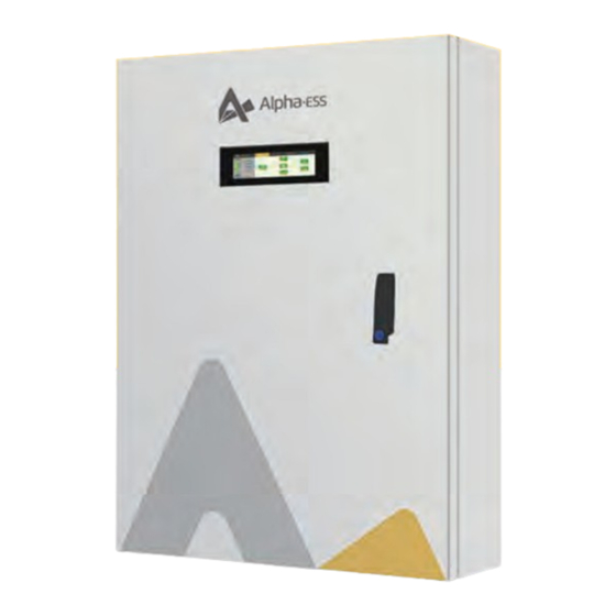
Summary of Contents for Alpha ESS Backup Box-PLUS
- Page 1 QUICK INSTALLATION GUIDE Backup Box-PLUS...
- Page 2 Parting List Backup Box-PLUS M8 expansion screw X4 Quick installation guide X1 Positioning board x1...
-
Page 3: System Wiring Diagram
Grid Load1 Load2 Load3 PV Panel Backup Box-PLUS wiring diagram for three-phase inverter. Please connect PE cable between Backup Box and the Backup Box-PLUS wiring diagram for inverter. If the inverter does not have PE port, these is single-phase inverter. - Page 4 Instruction ① ① ② ③ ① Power connection port ④ ② Communication port ③ LCD Screen ④ Lock ② ③ ① ③ ① Insulating plate ② Insulating plate ④ ⑤ ③ LCD Screen ④ Control switch ① Control panel ④ ②...
-
Page 5: Installation
Installation Step 1 Step 2 Take out the Backup Box-PLUS and accessories from the Place the cardboard on the wall where the Backup Box-PLUS package. will be installed, and mark on the wall according to holes on the cardboard. Note: Please pay... - Page 6 Step 5 Step 6 Lock the expansion screws into the two upper holes. Hang the Backup Box-PLUS on the installed expansion bolt. Note: Reserve a distance of 3-8mm between the bottom of the expansion...
- Page 7 Installation Step 7 Step 8 Use the key to open the upper cover, Lock the two expansion and use the SW10 sleeve to lock the screws at the bottom. two expansion screws above. Note: The tool used in this step should be matched with the extension rod (about 20cm).
- Page 8 Installation Step 10 Step 11 Connect the backup cables. Connect the grid cables. Note: When connecting cables, the wire harness must pass through the rubber plug at the bottom. The rubber plug should be cut with a knife along the middle cross.
- Page 9 Installation Step 12 Step 13 Connect the Load cables. Connect the PV-INV cables.
- Page 10 Installation Step 14 Step 15 Connect the AC cables. Install the insulation plate removed in step 10. Step 16 Connect the communication cables. To EMS Meter Port Note: The cable harness must be passed through the cable tie which is installed on the insulation plate. Then, tighten the cable tie.
-
Page 11: Dip Switch Description
Installation Configuration Step 17 Configuration on AlphaAPP DIP Switch Configuration Step 1 When the system mode is DIP Switch Description selected as DC, only tick "Meter" on the right of the Dial to "OFF" for three-phase system "Grid Meter" . and "ON"... - Page 12 Configuration Configuration on AlphaCloud. Step 1 Log in to https:/ /www.alphaess.com/, and input the system SN to check the status of your system.
- Page 13 Configuration Configuration on AlphaCloud. Step 2 When the system mode is selected as DC, click the button under the "Grid Meter" to make it green. When the system mode is selected as AC or Hybrid, click the buttons under the "Grid Meter" and "PV side meter" to make both green.
- Page 14 Configuration Configuration on AlphaCloud. Step 4 Please log in to the AlphaCloud page, select "System Setup", and click "Backup Box".
- Page 15 Configuration Configuration on AlphaCloud. Step 5 Select "Enable Backup Box" and set different priorities and minimum SOC values for each phase.
- Page 16 Configuration Configuration on AlphaCloud. Step 6 Complete all the setting steps above and click "Save" to enable the Backup Box function.
-
Page 17: Specification
Specification Model Backup Box-PLUS Phase Three Phase Communication RS-485 Display -10 ℃ ~ 50 ℃ Operating Temperature Humidity 15% ~ 85% IP Protection IP21 Dimension (W x D x H) 410 x 169 x 605 mm Warranty 5 Years Nominal Backup Power 10 kW 184 ~ 264.5 V (L-N) - Page 18 @AlphaESS @AlphaEnergyStorageSystem @AlphaESS @alpha_ess Headquarter: Alpha ESS Co., Ltd. Suzhou: Alpha ESS Suzhou Co., Ltd. Australia: Alpha ESS Australia Pty. Ltd. UK: Alpha ESS UK Co., Ltd +86 513 806 068 91 +86 512 6828 7609 +61 402 500 520 (Sales) uk@alpha-ess.com...


Need help?
Do you have a question about the Backup Box-PLUS and is the answer not in the manual?
Questions and answers