Table of Contents
Advertisement
Advertisement
Table of Contents

Related Manuals for Delta Electronics ASDA-B Series


Summary of Contents for Delta Electronics ASDA-B Series
- Page 2 Contents of this manual This manual is a user guide that provides the information on how to install, operate and maintain ASDA-B series AC servo drives and ECMA series AC servo motors. The contents of this manual are including the following topics:...
- Page 3 PLEASE READ PRIOR TO INSTALLATION FOR SAFETY. ASDA-B series drives are open type servo drives and must be installed in an NEMA enclosure such as a protection control panel during operation to comply with the requirements of the international safety standards.
-
Page 4: Unpacking Check
As a charge may still remain in the drive with hazardous voltages even after power has been removed, be sure to wait at least 10 minutes after power has been removed before performing any wiring and/or inspection. Revision January, 2009 Preface|ASDA-B Series... - Page 5 Preface|ASDA-B Series It is not recommended to frequently power the drive on and off. Do not turn the drive off and on more than once per minute as high charging currents within the internal capacitors may cause damage. Main Circuit Terminal Wiring Insert only one wire into one terminal on the terminal block.
-
Page 6: Table Of Contents
Chapter 1 Unpacking Check and Model Explanation... 1-1 1.1 Unpacking Check ... 1-1 1.2 Model Explanation ... 1-3 1.2.1 Nameplate Information ... 1-3 1.2.2 Model Name Explanation ... 1-4 1.3 Servo Drive and Servo Motor Combinations... 1-6 1.4 Servo Drive Features... 1-7 1.5 Control Modes of Servo Drive ... -
Page 7: Table Of Contents
Table of Contents|ASDA-B Series 3.2 Basic Wiring... 3-9 3.3 Input / Output Interface Connector -CN1... 3-12 3.3.1 CN1 Terminal Identification ... 3-12 3.3.2 Signals Explanation of Connector CN1 ... 3-13 3.3.3 User-defined DI and DO signals... 3-18 3.3.4 Wiring Diagrams of I/O Signals (CN1)... 3-20 3.4 Encoder Connector CN2 ... -
Page 8: Table Of Contents
AutoMode (PI) Tuning Flowchart... 5-15 5.5.4 AutoMode (PDFF) Tuning Flowchart... 5-17 5.5.5 Limit of Load Inertia Estimation ... 5-18 5.5.6 Relationship between Tuning Modes and Parameters ... 5-19 5.5.7 Gain Adjustment in Manual Mode ... 5-20 Revision January, 2009 Table of Contents|ASDA-B Series... -
Page 9: Table Of Contents
Table of Contents|ASDA-B Series Chapter 6 Control Modes of Operation ... 6-1 6.1 Control Modes of Operation ... 6-1 6.2 Position Control Mode ... 6-2 6.2.1 Command Source of Position Control Mode ... 6-2 6.2.2 Structure of Position Control Mode ... 6-3 6.2.3... -
Page 10: Table Of Contents
9.2 Maintenance ... 9-2 9.3 Life of Replacement Components ... 9-2 Chapter 10 Troubleshooting... 10-1 10.1 Fault Messages Table ... 10-1 10.2 Potential Cause and Corrective Actions... 10-3 10.3 Clearing Faults ... 10-12 Revision January, 2009 Table of Contents|ASDA-B Series... -
Page 11: Table Of Contents
Table of Contents|ASDA-B Series Chapter 11 Specifications ... 11-1 11.1 Specifications of Servo Drive (ASDA-B Series) ... 11-1 11.2 Specifications of Servo Motor (ECMA Series) ... 11-4 11.3 Dimensions of Servo Drive... 11-7 11.4 Servo Motor Speed-Torque Curves (T-N Curve) ... 11-10 11.5 Overload Characteristics ... - Page 12 Due to constantly growing product range, technical improvement and alteration or changed texts, figures and diagrams, we reserve the right of this manual contained information change without prior notice. Coping or reproducing any part of this manual, without written consent of Delta Electronics Inc. is prohibited. Technical Support and Service Welcome to contact us or visit our web site (http://www.delta.com.tw/industrialautomation/) if you need any...
- Page 13 Table of Contents|ASDA-B Series This page intentionally left blank Revision January, 2009...
-
Page 14: Chapter 1 Unpacking Check And Model Explanation
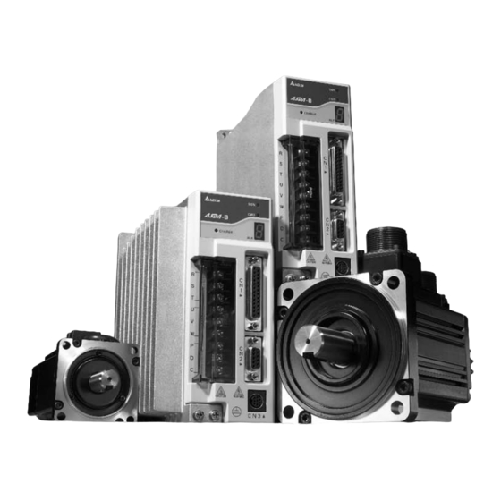
Chapter 1 Unpacking Check and Model Explanation Unpacking Check After receiving the AC servo drive, please check for the following: Ensure that the product is what you have ordered. Verify the part number indicated on the nameplate corresponds with the part number of your order (Please refer to Section 1.2 for details about the model explanation). - Page 15 Chapter 1 Unpacking Check and Model Explanation|ASDA-B Series Delta AC Servo Drive and Motor Revision January 2009...
-
Page 16: Model Explanation
Model Explanation 1.2.1 Nameplate Information ASDA-B Series Servo Drive Nameplate Explanation Serial Number Explanation ECMA Series Servo Motor Nameplate Explanation Serial Number Explanation Revision January 2009 Chapter 1 Unpacking Check and Model Explanation|ASDA-B Series... -
Page 17: Model Name Explanation
Chapter 1 Unpacking Check and Model Explanation|ASDA-B Series 1.2.2 Model Name Explanation ASDA-B Series Servo Drive Revision January 2009... - Page 18 Chapter 1 Unpacking Check and Model Explanation|ASDA-B Series ECMA Series Servo Motor Revision January 2009...
-
Page 19: Servo Drive And Servo Motor Combinations
Servo Drive and Servo Motor Combinations The table below shows the possible combination of Delta ASDA-B series servo drives and ECMA series servo motors. The boxes ( ) in the model names are for optional configurations. (Please refer to Section 1.2... -
Page 20: Servo Drive Features
2) CMD LED: A lit CMD LED indicates that the servo drive is ON (Servo On) or the motor speed is equal to or higher than the setting value of P1-38 (>=P1-38 (ZSPD)). Revision January 2009 Chapter 1 Unpacking Check and Model Explanation|ASDA-B Series... -
Page 21: Control Modes Of Servo Drive
Chapter 1 Unpacking Check and Model Explanation|ASDA-B Series Control Modes of Servo Drive The Delta Servo can be programmed to provide five single and three dual modes of operation. Their operation and description is listed in the following table. Mode... -
Page 22: Chapter 2 Installation And Storage
Installation Notes Pay close attention on the following installation notes: Do not bend or strain the connection cables between servo drive and motor. When mounting servo drive, make sure to tighten screws to secure the drive in place. If the servo motor shaft is coupled directly to a rotating device ensure that the alignment specifications of the servo motor, coupling, and device are followed. -
Page 23: Installation Conditions
Chapter 2 Installation and Storage|ASDA-B Series Installation Conditions Operating Temperature ASDA-B Series Servo Drive ECMA Series Servo Motor The ambient temperature of servo drive for long-term reliability should be under 45°C (113°F). If the ambient temperature of servo drive is greater than 45°C (113°F), please install the drive in a well- ventilated location and do not obstruct the airflow for the cooling fan. -
Page 24: Installation Procedure And Minimum Clearances
Chapter 2 Installation and Storage|ASDA-B Series Installation Procedure and Minimum Clearances Installation Procedure Incorrect installation may result in a drive malfunction or premature failure of the drive and or motor. Please follow the guidelines in this manual when installing the servo drive and motor. - Page 25 Chapter 2 Installation and Storage|ASDA-B Series Minimum Clearances Side by Side Installation 4.0in 100mm min. 1.6in 40mm min. 4.0in 100mm min. 2.0in 50mm min. 0.8in 0.8in 20mm 20mm min. min. 2.0in 50mm min. 0.4in 0.4in 10mm 10mm min. min. Air flow 4.0in...
-
Page 26: Chapter 3 Connections And Wiring
This chapter provides information on wiring ASDA-B series products, the descriptions of I/O signals and gives typical examples of wiring diagrams. Connections 3.1.1 Connecting to Peripheral Devices In Figure 3.1, it briefly explains how to connect each peripheral device. Figure 3.1... -
Page 27: Servo Drive Connectors And Terminals
Chapter 3 Connections and Wiring|ASDA-B Series 3.1.2 Servo Drive Connectors and Terminals Terminal Terminal Identification Description R, S, T Main circuit terminal U, V, W Servo motor output Regenerative P, D, C resistor terminal Ground terminal two places I/O connector... - Page 28 For the connectors and cables specifications, please refer to section 3.1.6 for details. In this manual, actual measured values are in metric units. The recommended wire lengths in (imperial units) are for reference only. Please use metric for precise measurements. Revision January 2009 Chapter 3 Connections and Wiring|ASDA-B Series...
-
Page 29: Wiring Methods
Chapter 3 Connections and Wiring|ASDA-B Series 3.1.3 Wiring Methods For servo drives 1.5kW and below the input power can be either single or three-phase. For drives 2kW and above only three-phase connections are available. In the wiring diagram figures 3.2 & 3.3: Power ON : contact “a”... -
Page 30: Motor Power Cable Connector Specifications
ECMA-C30804 7 (400W) ECMA-C30807 S (750W) ECMA-C30602 S (200W) ECMA-C30604 S (400W) ECMA-C30804 7 (400W) ECMA-C30807 S (750W) Revision January 2009 Chapter 3 Connections and Wiring|ASDA-B Series U, V, W / Electromagnetic Brake Connector HOUSING: JOWLE (C4201H00-2*2PA) HOUSING: JOWLE (C4201H00-2*3PA) Terminal Identification... - Page 31 Chapter 3 Connections and Wiring|ASDA-B Series Motor Model Name ECMA-G31303 S (300W) ECMA-E31305 S (500W) ECMA-G31306 S (600W) ECMA-G31309 S (900W) ECMA-C31010 S (1000W) ECMA-E31310 S (1000W) ECMA-E31315 S (1500W) ECMA-C31020 S (2000W) ECMA-E31320 S (2000W) ECMA-E31820 S (2000W) Terminal...
-
Page 32: Encoder Connector Specifications
Terminal Identification (Black AMP (1- (Black) /Red) 172161-9) Terminal Identification (Blue 3106A-20- (Blue) /Black) Revision January 2009 Chapter 3 Connections and Wiring|ASDA-B Series Encoder Connector HOUSING: AMP (1-172161-9) 3106A-20-29S (White (Orange (White) (Orange) /Red) /Red) (Green (Yellow (Green) (Yellow) /Black) -
Page 33: Cable Specifications For Servo Drive And Servo Motor
Chapter 3 Connections and Wiring|ASDA-B Series 3.1.6 Cable Specifications for Servo Drive and Servo Motor Servo Drive and Servo Motor ASD-B0121-A ECMA-C30401 S ASD-B0221-A ECMA-C30602 S ECMA-C30604 S ECMA-C30804 7 ASD-B0421-A ECMA-E31305 S ECMA-G31303 S ECMA-C30807 S ASD-B0721-A ECMA-G31306 S... -
Page 34: Basic Wiring
Chapter 3 Connections and Wiring|ASDA-B Series Basic Wiring Figure 3.4 Basic Wiring Schematic of 400W and below models Revision January 2009... - Page 35 Chapter 3 Connections and Wiring|ASDA-B Series Figure 3.5 Basic Wiring Schematic of 750W models 3-10 Revision January 2009...
- Page 36 Chapter 3 Connections and Wiring|ASDA-B Series Figure 3.6 Basic Wiring Schematic of 1kW and above models 3-11 Revision January 2009...
-
Page 37: Input / Output Interface Connector -Cn1
Chapter 3 Connections and Wiring|ASDA-B Series Input / Output Interface Connector -CN1 The CN1 Interface Connector provides access to three signal groups: General interface for the analog speed and torque control, encoder reference signal from the motor, open collector and line driver inputs, and reference voltages. -
Page 38: Signals Explanation Of Connector Cn1
Detailed in Tables 3.B and 3.C are the DO and DI functions with their corresponding signal name and wiring schematic. The factory default settings of the DI and DO signals are detailed in Table 3.F. Revision January 2009 Chapter 3 Connections and Wiring|ASDA-B Series Details Motor speed command: -10V to +10V, corresponds to the maximum speed programmed P1-55 Maximum Speed Limit (Factory default 3000 RPM). - Page 39 Chapter 3 Connections and Wiring|ASDA-B Series All of the DI's and DO's and their corresponding pin numbers are factory set and nonchangeable, however, all of the assigned signals and control modes are user changeable. For Example, the factory default setting of DO1 (pin 16) is SRDY (servo ready) signal, but it can be assigned to SON (Servo On) signal and vise versa.
- Page 40 T , Tz SPDLM GNUM0 SPD0 SPD1 Revision January 2009 Chapter 3 Connections and Wiring|ASDA-B Series Pin No. Details Servo warning output. WARN is activated when the drive has detected Reverse limit error, Forward limit error, Emergency stop, Serial communication error, and Undervoltage these fault conditions.
- Page 41 Chapter 3 Connections and Wiring|ASDA-B Series Assigned Control Mode Signal TCM0 TCM1 Sz , S , P Sz , S , Tz T , Tz , P EMGS CCWL P , S TLLM P , S TRLM Footnote *2: The "state" of the input function may be turned ON or OFF as it will be dependant on the settings of P2-18~P2-20.
- Page 42 SRDY ZSPD TSPD TPOS ALRM BRKR WARN Revision January 2009 Chapter 3 Connections and Wiring|ASDA-B Series The factory default settings of DI signals Function Servo On Alarm Reset Gain switching in speed and position mode Pulse clear Zero speed CLAMP...
-
Page 43: User-Defined Di And Do Signals
Chapter 3 Connections and Wiring|ASDA-B Series 3.3.3 User-defined DI and DO signals If the default DI and DO signals could not be able to fulfill the users’ requirements, there are still user- defined DI and DO signals. The setting method is easy and they are all defined via parameters. The user-defined DI and DO signals are defined via parameters P2-10 to P2-15 and P2-18 to P2-20. - Page 44 TPOS ALRM BRKR WARN Revision January 2009 Chapter 3 Connections and Wiring|ASDA-B Series Setting of parameter P2-10 to P2-15: Description Speed / Torque mode switching (OFF: Speed, ON: Torque) Torque / Position mode switching (OFF: Torque, ON: Position) Emergency stop (contact b)
-
Page 45: Wiring Diagrams Of I/O Signals (Cn1)
Chapter 3 Connections and Wiring|ASDA-B Series 3.3.4 Wiring Diagrams of I/O Signals (CN1) The valid voltage range of analog input command in speed and torque mode is -10V ~+10V. The command value can be set via relevant parameters. C1: Speed / Torque analog signal input There are two kinds of pulse inputs, Line driver input and Open-collector input. - Page 46 C2-2: Pulse input (Open collector – external power) Please ensure to connect the resistor or the photocoupler may be damaged due to excessive current. Revision January 2009 Chapter 3 Connections and Wiring|ASDA-B Series Approx. 19 /SIGN 20 SIGN Approx. 21 /PULSE 22 PULSE COM- Approx.
- Page 47 Chapter 3 Connections and Wiring|ASDA-B Series C3: Pulse input (Line Driver) Because this photocoupler is a unidirectional optocoupler, please pay close attention on the current direction of input pulse command. Be sure to connect a diode when the drive is applied to inductive load.
- Page 48 C10: Encoder output signal (Line driver) Revision January 2009 Chapter 3 Connections and Wiring|ASDA-B Series C7: Wiring of DO signal, for the use of external power supply, inductive load C9: Wiring of DI signal, for the use of internal...
-
Page 49: Encoder Connector Cn2
Chapter 3 Connections and Wiring|ASDA-B Series Encoder Connector CN2 Integrated within the servo motor is an incremental encoder with 2,500PPR and commutation signal. When power is first applied to the servo drive, control algorithms detect the motor's rotor position through imbedded sensors in the motor within 500msec approximately. -
Page 50: Serial Communication Connector Cn3
1) In order to avoid the communication error, if the users use their own communication connector, ensure the circuit between the connector case and all pins is not closed. Revision January 2009 Chapter 3 Connections and Wiring|ASDA-B Series CN3 Terminal Signal Identification Terminal Identification For data transmission of the servo drive. -
Page 51: Connection Between Pc/Keypad And Connector Cn3
Chapter 3 Connections and Wiring|ASDA-B Series 2) When using RS-232 communication, the user can use the communication cable provided by Delta PLC directly. (The PLC communication cable is compatible with all Delta Servo systems for the users’ convenience) 3.5.2 Connection between PC/Keypad and Connector CN3... -
Page 52: Standard Connection Example
Chapter 3 Connections and Wiring|ASDA-B Series Standard Connection Example 3.6.1 Position Control Mode 3-27 Revision January 2009... -
Page 53: Speed Control Mode
Chapter 3 Connections and Wiring|ASDA-B Series 3.6.2 Speed Control Mode 3-28 Revision January 2009... -
Page 54: Torque Control Mode
Chapter 3 Connections and Wiring|ASDA-B Series 3.6.3 Torque Control Mode 3-29 Revision January 2009... - Page 55 Chapter 3 Connections and Wiring|ASDA-B Series This page intentionally left blank. 3-30 Revision January 2009...
-
Page 56: Chapter 4 Display And Operation
This chapter describes the basic operation of the digital keypad and the features it offers. There are several modes of operation: Monitor, Parameter, Parameter Setting, Save, Write and Fast Edit Mode. In Monitor mode, users can display the monitor status. In Parameter mode, users can display and view the parameter name, unit and setting value, and also can navigate in parameter groups. - Page 57 Chapter 4 Display and Operation|ASDA-B Series Name 2 line × 16 character LCD display shows the monitor codes, parameter settings and LCD Display operation values of the AC servo drive. SON LED (Servo On Indicator). A lit LED illuminates to indicate that the servo drive is enabled.
-
Page 58: Display Flowchart
Parameter Mode P0-00:VER GROUP0 P1-00:PTT GROUP1 P2-00:KPP GROUP2 P3-00:ADR GROUP3 P4-00:ASH1 GROUP4 P8-00:VERSION GROUP8 Revision January 2009 Chapter 4 Display and Operation|ASDA-B Series STS01:Fb REV STS02:CMD PULSE MODE P0-01:ALE 0.005 SHIFT P1-01:CTL SHIFT P2-01:PPR rad/s SHIFT P3-01:BRT SHIFT P4-01:ASH2... - Page 59 Chapter 4 Display and Operation|ASDA-B Series SAVE Mode (Save parameter settings from the Drive to the Keypad) 1. When the power is applied to the AC servo drive, the digital keypad will enter into the monitor mode first. 2. In monitor mode, pressing SAVE key can switch to SAVE mode.
- Page 60 KPD WRITE 0.006 ROM00:BL003-00 KPD WRITE 0.006 ROM01:BL003-01 KPD WRITE 0.006 ROM24:BL003-24 Revision January 2009 Chapter 4 Display and Operation|ASDA-B Series MODE Press key to return to previous display WRITE ALARM 47 MODEL MATCH ERR KPD WRITE 0.006 ROM00:writing...
- Page 61 Chapter 4 Display and Operation|ASDA-B Series Fast Edit Mode (Fast Editing, Static & Dynamic Auto-tuning) 1. When the power is applied to the AC servo drive, the digital keypad will enter into the monitor mode first. 2. In monitor mode, pressing Fast Edit key can switch to Fast Edit mode.
- Page 62 Fast Edit FEDIT:AUTO D -T Fast Edit FEDIT:AUTO D -L MODE Fast Edit FEDIT:AUTO D -L PR Dload Revision January 2009 Chapter 4 Display and Operation|ASDA-B Series STS00:Fb PULSE pulse MODE Fast Edit FEDIT:PR EDIT FEDIT:AUTO S Fast Edit MODE...
-
Page 63: Status Display
Chapter 4 Display and Operation|ASDA-B Series 4.1.3 Status Display Save Setting Display After the SET key is pressed, LCD display will show the following display messages for approx. one second according to different status. Display Message Abort Setting Display Display Message... -
Page 64: Monitor Setting Display
P0-02 Display Message Setting T S 1 T S 1 Revision January 2009 Chapter 4 Display and Operation|ASDA-B Series Motor feedback pulse number Motor feedback rotation number Pulse counts of pulse command Rotation number of pulse command Position error counts... - Page 65 Chapter 4 Display and Operation|ASDA-B Series P0-02 Display Message Setting T S 1 T S 1 T S 1 T S 1 The following table lists the display examples of monitor value: Display Message 4-10 Peak load Main circuit voltage...
-
Page 66: Fault Code Display Operation
ASH1 to ASH5 in order. ASH1 indicates the most recent occurred fault code, ASH2 is the previous occurred fault code before ASH1 and so on. Figure 4.8 Fault Code History Revision January 2009 Chapter 4 Display and Operation|ASDA-B Series Current Display Fault Code History Status Display 4-11... -
Page 67: Jog Operation
Chapter 4 Display and Operation|ASDA-B Series 4.1.5 JOG Operation After entering parameter mode P4-05, the users can follow the following steps to perform JOG operation or press JOG key on the digital keypad to enter into parameter setting mode of P4-05 directly. - Page 68 Figure 4.9 Revision January 2009 Chapter 4 Display and Operation|ASDA-B Series MODE r p m 4-13...
-
Page 69: Do Force Output Diagnosis Operation
Chapter 4 Display and Operation|ASDA-B Series 4.1.6 DO Force Output Diagnosis Operation For testing, the digital outputs can be forced to be activated (ON) or inactivated (OFF) by using parameter P4-06. Follow the setting method in Figure 4.10 to enter into DO force output diagnosis operation (OP x) mode (“x”... -
Page 70: Di Diagnosis Operation
LCD display. When the segment lit and display on the screen, it means that the corresponding digital input signal is ON. Figure 4.12 Revision January 2009 Chapter 4 Display and Operation|ASDA-B Series DI6: ON DI5: ON DI4: ON... -
Page 71: Parameters Read And Write
Chapter 4 Display and Operation|ASDA-B Series 4.1.9 Parameters Read and Write Digital keypad provides the servo parameters read and write function not only for the servo drive but also for PC side. The function of parameter read and write must be set via the PC software (Please see Figure 4.6 &... - Page 72 Chapter 4 Display and Operation|ASDA-B Series Figure 4.7 4-17 Revision January 2009...
-
Page 73: Asd-Pu-01B
Chapter 4 Display and Operation|ASDA-B Series ASD-PU-01B 4.2.1 Description of Digital Keypad ASD-PU-01B The digital keypad includes the ASD-PU-01B display panel and function keys. The Figure 4.8 shows all of the features of the ASD-PU-01B digital keypad and an overview of their functions. - Page 74 7. When the parameter setting is completed, LED display will show the end code “-END-“ and automatically return back to parameter mode. Revision January 2009 Chapter 4 Display and Operation|ASDA-B Series Function ) mode and WRITE ( ) mode, pressing UP and DOWN...
- Page 75 Chapter 4 Display and Operation|ASDA-B Series Figure 4.9 4-20 Revision January 2009...
- Page 76 “Memory Block Clear” function first (Please see the description of parameter P8-11). Revision January 2009 Chapter 4 Display and Operation|ASDA-B Series Save parameter settings from the Drive to the Keypad) . After the address is saved to the keypad, the LED display will...
- Page 77 Chapter 4 Display and Operation|ASDA-B Series Figure 4.10 4-22 Revision January 2009...
- Page 78 Delta Servo Drive PC software, ASDAB_SW. Revision January 2009 Chapter 4 Display and Operation|ASDA-B Series Parameter settings written out from Keypad to the Drive) . After the address is written, the LED display will show “0XXXX”...
- Page 79 Chapter 4 Display and Operation|ASDA-B Series Figure 4.11 4-24 Revision January 2009...
- Page 80 9. In Fast Edit mode, pressing MODE key once can return to the previous display and finally exit the Fast Edit mode (Please see Figure 4.12 below). Figure 4.12 Revision January 2009 Chapter 4 Display and Operation|ASDA-B Series Fast Editing Function) 4-25...
- Page 81 Chapter 4 Display and Operation|ASDA-B Series Dynamic Auto-tuning Mode ( 1. When the power is applied to the AC servo drive, the digital keypad will enter into the monitor mode first. 2. In monitor mode, pressing FUNC key first. Then, pressing UP key two times or DOWN key five times can switch to Dynamic Auto-tuning mode.
- Page 82 5. In Fast Edit mode, pressing MODE key once can return to the previous display and finally exit the Fast Edit mode (Please see Figure 4.14 below). Figure 4.14 Revision January 2009 Chapter 4 Display and Operation|ASDA-B Series Static Auto-tuning Function) 4-27...
- Page 83 Chapter 4 Display and Operation|ASDA-B Series 4.2.3 Status Display Save Setting Display After the SET key is pressed, LED display will show the following display messages for approx. one second according to different status. Display Message Abort Setting Display Display Message...
- Page 84 P0-02 Display Message Setting Revision January 2009 Chapter 4 Display and Operation|ASDA-B Series Description Motor feedback pulse number Motor feedback rotation number Pulse counts of pulse command Rotation number of pulse command...
- Page 85 Chapter 4 Display and Operation|ASDA-B Series P0-02 Display Message Setting The following table lists the display examples of monitor value: Display Message 4-30 Description Ratio of load inertia to Motor inertia IGBT Temperature of power supply module Description Positive value display.
- Page 86 Step 5 To change JOG speed again, press the MODE key. After JOG speed is changed, press the SET key and the JOG operation will run again. Refer back to #2 and #3 to change speed. Revision January 2009 Chapter 4 Display and Operation|ASDA-B Series 4-31...
- Page 87 Chapter 4 Display and Operation|ASDA-B Series NOTE 1) JOG operation is effective only when Servo On (when the servo drive is enabled). 2) Before using JOG function, please ensure to confirm that P2-10 (DI1) is set to 101 (Servo On).
- Page 88 Chapter 4 Display and Operation|ASDA-B Series 4.2.6 DO Force Output Diagnosis Operation For testing, the digital outputs can be forced to be activated (ON) or inactivated (OFF) by using parameter P4-06. Follow the setting method in Figure 4.17 to enter into DO force output diagnosis operation (OP x) mode (“x”...
- Page 89 Chapter 4 Display and Operation|ASDA-B Series 4.2.7 DI Diagnosis Operation Following the setting method in Figure 4.18 can perform DI diagnosis operation (parameter P4-07). According to the ON and OFF status of the digital inputs DI1 to DI6, the corresponding status will display on the servo drive LED display.
-
Page 90: Do Diagnosis Operation
Chapter 4 Display and Operation|ASDA-B Series 4.2.8 DO Diagnosis Operation Following the setting method in Figure 4.19 can perform DO diagnosis operation (parameter P4-09). According to the ON and OFF status of the digital outputs DO1 to DO3, the corresponding status will display on the servo drive LED display. - Page 91 Chapter 4 Display and Operation|ASDA-B Series 4.2.9 Parameters Read and Write Digital keypad provides the servo parameters read and write function not only for the servo drive but also for PC side. The function of parameter read and write must be set via the PC software (Please see Figure 4.20 &...
- Page 92 Chapter 4 Display and Operation|ASDA-B Series Figure 4.21 4-37 Revision January 2009...
- Page 93 Chapter 4 Display and Operation|ASDA-B Series This page intentionally left blank. 4-38 Revision January 2009...
-
Page 94: Chapter 5 Trial Run And Tuning Procedure
Chapter 5 Trial Run and Tuning Procedure This chapter describes trial run and tuning procedure for servo drive and motor. Trial run, which is divided into two parts, one part is to introduce the trial run without load, and the other part is to introduce trial run with load. - Page 95 Chapter 5 Trial Run and Tuning Procedure|ASDA-B Series Item Ensure that the cables are not damaged, stressed excessively or loaded heavily. When the motor is running, pay close attention on the connection of the cables and notice that if they are damaged, frayed or over extended.
-
Page 96: Applying Power To The Drive
Use voltmeter to check whether the input voltage falls within the rated input voltage. Use voltmeter to check whether the input voltage is within the specified limit. Revision January 2009 Chapter 5 Trial Run and Tuning Procedure|ASDA-B Series displays and blinks on the LCD display, it indicates that the testing... - Page 97 Chapter 5 Trial Run and Tuning Procedure|ASDA-B Series 2) When display shows: Encoder error: Check if the wiring is correct. Check if the encoder wiring (CN2) of servo motor is loose or incorrect. Corrective Actions: Check if the user performs wiring recommended in the user manual.
- Page 98 Use voltmeter to check whether input voltage of main circuit is normal. Use voltmeter to check whether the input voltage is within the specified specification. 8) When display shows: Revision January 2009 Chapter 5 Trial Run and Tuning Procedure|ASDA-B Series...
- Page 99 Chapter 5 Trial Run and Tuning Procedure|ASDA-B Series Magnetic field error: Corrective Actions: Check if the encoder is abnormal. Verify the encoder connector. 9) When display shows: Input power phase loss: Corrective Actions: Verify the main circuit power R, S, T. Check for possible poor connection on the power cable.
-
Page 100: Jog Trial Run Without Load
However, if CWL (ALE14, Reverse inhibit limit) or CCWL (ALE15, Forward inhibit limit) occurs during JOG operation, the users can still use JOG operation without problem. Please refer to the description of Section 4.1.5 in Chapter 4. Revision January 2009 Chapter 5 Trial Run and Tuning Procedure|ASDA-B Series... -
Page 101: Asd-Pu-01B Tuning Flowchart
Chapter 5 Trial Run and Tuning Procedure|ASDA-B Series 5.3.2 ASD-PU-01B Tuning Flowchart STEP 1: Turn the drive ON through software. Ensure that there is no fault message display on the LED display and the servo drive is normal. STEP 2: Press FUNC key on the keypad first. Then, press UP key three times or DOWN key four times can enter into JOG operation mode automatically. -
Page 102: Speed Trial Run Without Load
DI6, i.e. set the setting value of parameter P2-15 to 0. All the digital inputs of Delta ASDA-B series are user-defined, and the user can set the DI signals freely. - Page 103 Chapter 5 Trial Run and Tuning Procedure|ASDA-B Series The settings of speed command: P1-09 is set to 3000 P1-10 is set to 100 P1-11 is set to -3000 STEP 3: The users can use DI1 to enable the servo drive (Servo ON).
-
Page 104: Tuning Procedure
200rpm shown on the right side display. 12. After select desired JOG speed, press SET key and the right side display show on the LCD display. Revision January 2009 Chapter 5 Trial Run and Tuning Procedure|ASDA-B Series Display Message T S 1 5-11... - Page 105 Chapter 5 Trial Run and Tuning Procedure|ASDA-B Series 13. Pressing UP key is forward rotation and pressing DOWN key is reverse rotation. 14. Execute JOG operation in low speed first. After the machine is running smoothly, then execute JOG operation in high speed.
-
Page 106: Tuning Flowchart
MODE key once and press SET key twice to view the display on the keypad. Check if the value of J_load /J_motor is adjusted to a fixed value and displayed on the keypad after acceleration and deceleration repeatedly. 5.5.1 Tuning Flowchart Revision January 2009 Chapter 5 Trial Run and Tuning Procedure|ASDA-B Series Tuning Procedure 5-13... -
Page 107: Load Inertia Estimation Flowchart
Chapter 5 Trial Run and Tuning Procedure|ASDA-B Series 5.5.2 Load Inertia Estimation Flowchart 5-14 Revision January 2009... -
Page 108: Automode (Pi) Tuning Flowchart
Chapter 5 Trial Run and Tuning Procedure|ASDA-B Series 5.5.3 AutoMode (PI) Tuning Flowchart P2-31 Auto Stiffness and Responsiveness Level (Default setting: 6) Function: This parameter allows user to set the stiffness and responsiveness level automatically. Users can control the stiffness and responsiveness according to application condition. When the setting value is higher, the stiffness and responsiveness is higher. - Page 109 Chapter 5 Trial Run and Tuning Procedure|ASDA-B Series Table 5.A P2-31 Value in AutoMode(PI) and the setting of Speed Loop Responsiveness and P2-25. Setting Value of P2-31 Speed Loop Responsiveness 5-16 Low-pass Filter Time Constant of Resonance Suppression (P2-25) 10 Hz...
-
Page 110: Automode (Pdff) Tuning Flowchart
Chapter 5 Trial Run and Tuning Procedure|ASDA-B Series 5.5.4 AutoMode (PDFF) Tuning Flowchart P2-31 Auto Stiffness and Responsiveness Level (Default setting: 6) Function: This parameter allows user to set the stiffness and responsiveness level automatically. Users can control the stiffness and responsiveness according to application condition. When the setting value is higher, the stiffness and responsiveness is higher. -
Page 111: Limit Of Load Inertia Estimation
Chapter 5 Trial Run and Tuning Procedure|ASDA-B Series Table 5.B P2-31 Value in AutoMode(PDFF) and the setting of Speed Loop Responsiveness. Setting Value of Speed Loop Responsiveness P2-31 5.5.5 Limit of Load Inertia Estimation 1. The accel. / decel. time for reaching 2000RPM must be below 1 second. The rotation speed must be above 200RPM. -
Page 112: Relationship Between Tuning Modes And Parameters
AutoMode (PDFF) [Fixed Inertia] (The inertia ratio is determined by P1-37) Revision January 2009 Chapter 5 Trial Run and Tuning Procedure|ASDA-B Series AutoSet User-defined Parameter Parameter P2-00 (Proportional Position Loop Gain) P2-04 (Proportional Speed Loop Gain) P2-06 (Speed Integral Compensation) -
Page 113: Gain Adjustment In Manual Mode
Chapter 5 Trial Run and Tuning Procedure|ASDA-B Series 5.5.7 Gain Adjustment in Manual Mode The position and speed responsiveness selection is depending on and determined by the the control stiffness of machinery and conditions of applications. Generally, high reponsiveness is essential for the high frequency positioning control of mechanical facilities and the applications of high precision process system. - Page 114 Chapter 5 Trial Run and Tuning Procedure|ASDA-B Series NLP, Parameter P2-25 Low-pass Filter Time Constant (Resonance Suppression) When the value of (J_load / J_motor) is high, the responsiveness of speed loop may decrease. At this time, the users can increase the setting value of KVP (P2-04) to keep the responsiveness of speed loop.
- Page 115 Chapter 5 Trial Run and Tuning Procedure|ASDA-B Series This page intentionally left blank. 5-22 Revision January 2009...
-
Page 116: Chapter 6 Control Modes Of Operation
Control Modes of Operation The Delta ASDA-B series Servo can be programmed to provide five single and three dual modes of operation. Their operation and description is listed in the following Table 6.A. Mode External Position Control Speed Control Internal Speed... -
Page 117: Position Control Mode
The position control mode (P mode) is usually used for the applications requiring precision positioning, such as industry positioning machine, indexing table etc. Delta ASDA-B series servo drive supports one kind of command source in position control mode. That is external pulse train with direction which can control the rotation angle of servo motor. -
Page 118: Structure Of Position Control Mode
Pulse type Pulse selection Signal INHIBIT Revision January, 2009 Chapter 6 Control Modes of Operation|ASDA-B Series Input pulse interface Max. input pulse frequency Line driver Open collector 0=Positive Logic Forward... -
Page 119: Electronic Gear Ratio
Chapter 6 Control Modes of Operation|ASDA-B Series 6.2.3 Pulse Inhibit Input Function (INHP) INHP is activated via digital inputs (Please refer to parameter P2-10 ~ P2-15 and DI INHP(07) in Table 7.A).When the drive is in position mode, if INHP is activated, the external pulse input command is not valid and the motor will stop. - Page 120 Travel distance per pulse = T Motor ( encoder signal output: A/B, Z ) Encoder PPR: 2500 puls e Revision January, 2009 Chapter 6 Control Modes of Operation|ASDA-B Series DI Status Selected Electronic Gear Not select (Note 1) f1: Pulse input...
-
Page 121: Low-Pass Filter
Chapter 6 Control Modes of Operation|ASDA-B Series When the electronic gear ratio is not used When the electronic gear ratio is not used 6.2.5 Low-pass Filter Relevant parameters: Smooth Constant of Position Command (Low- P1 - 08 PFLT pass Filter) - Page 122 When using position smooth command, increase gain can improve position track deviation. When not using position smooth command, decrease gain can improve the resonance condition Revision January, 2009 Chapter 6 Control Modes of Operation|ASDA-B Series Communication Addr.: 0200H Related Section: Section 6.2.6, P2-27...
- Page 123 Chapter 6 Control Modes of Operation|ASDA-B Series of mechanical system. In PDFF control AutoMode, the value of this parameter will be changed in accordance with the setting value of parameter P2-31 automatically (Please refer Table 6.D & 6.E in Chapter 6).
-
Page 124: Command Source Of Speed Control Mode
The speed control mode (S or Sz) is usually used on the applications of precision speed control, such as CNC machine, etc. ASDA-B series servo drive supports two kinds of command sources in speed control mode. One is external analog signal and the other is internal parameter. The external analog signal is from external voltage input and it can control the speed of servo motor. -
Page 125: Structure Of Speed Control Mode
Chapter 6 Control Modes of Operation|ASDA-B Series NOTE 1) In speed control mode, if the users want to adjust analog speed input offset value, please refer to parameter 4-22 for the operation. 6.3.2 Structure of Speed Control Mode Basic Structure: In the figure above, the speed command processing is used to select the command source of speed control according to chapter 6.3.1, including proportional gain (P1-40) and S-curve filter smoothing... -
Page 126: Smoothing Strategy Of Speed Control Mode
ASDA-B series servo drives also support the time calculation of completing speed command. T (ms) is the operation (running) time. S (rpm) is absolute speed command, i.e. the absolute value (the result) after starting speed subtracts the final speed. - Page 127 Chapter 6 Control Modes of Operation|ASDA-B Series Settings: It is used to determine the acceleration time to accelerate from 0 to its rated rotation speed. (When P1-36 is set to 0: Accel/Decel function is disabled, i.e. P1-34, P1-35 is disabled)
- Page 128 Analog Speed Command S-curve Filter ASDA-B series servo drives also provide Analog Speed Command S-curve Filter for the smoothing in response to a sudden analog input signal. Speed (rpm) 3000 -3000 The analog speed command S-curve filter is for the smoothing of analog input signal and its function is the same as the S-curve filter.
-
Page 129: Analog Speed Input Scaling
Chapter 6 Control Modes of Operation|ASDA-B Series 6.3.4 Analog Speed Input Scaling The analog voltage between V_REF and GND determines the motor speed command. Using with parameter P1-40 (Max. Analog Speed Command) can adjust the speed control ramp and its range. -
Page 130: Timing Chart Of Speed Control Mode
Speed Control Block Diagram Feed Forward Differentiator Gain P2-07 Integrator Proportional Gain P2-04 Gain Switching Control Selection Revision January, 2009 Chapter 6 Control Modes of Operation|ASDA-B Series SPD0 SPD1 Proportional Gain P2-04 Switching P2-27 Rate P2-05 P2-27 Torque constant Current... - Page 131 Chapter 6 Control Modes of Operation|ASDA-B Series There are two turning modes of gain adjustment: Manual and Auto modes. The gain of ASDA-B series servo drives can be adjusted by using any one of two tuning modes. Manual Mode: User-defined loop gain adjustment. When using this mode, all auto and auxiliary function will be disabled.
- Page 132 Tuning Mode Selection Default: 0 Applicable Control Mode: P/S/T Unit: N/A Range: 0 ~ 12 Settings: ASD-PU-01A Revision January, 2009 Chapter 6 Control Modes of Operation|ASDA-B Series PDFF Structure (P2-32) Position Feed Proportional Forward Speed Loop Gain (%) Gain P2-04...
- Page 133 Chapter 6 Control Modes of Operation|ASDA-B Series • Tuning Mode Settings: 0: Manual mode 1: AutoMode (Continuous adjustment) The ratio of Load Inertia to servo motor inertia can be continuously adjusted. The level of stiffness and responsiveness are adjusted by parameter P2-31.
- Page 134 However, if the setting value is over high, it may generate vibration or noise. In Revision January, 2009 Chapter 6 Control Modes of Operation|ASDA-B Series Communication Addr.: 0125H Related Section: P2-31, P2-32, Section 6.3.6...
- Page 135 Chapter 6 Control Modes of Operation|ASDA-B Series AutoMode, the value of this parameter will be changed in accordance with the setting value of parameter P2-31 automatically (Please refer Table 6.D & 6.E in Chapter 6). Time constant of speed integral compensation: (1000/KVI) ms...
- Page 136 45deg of phase margin. Time Domain Speed Speed Revision January, 2009 Chapter 6 Control Modes of Operation|ASDA-B Series Gain Phase When the value of KVP is greater , the value of the responsiveness is also greater and the raising time is shorter.
- Page 137 Chapter 6 Control Modes of Operation|ASDA-B Series Speed Auto Mode (Continuous adjustment)) When Tuning Mode Settings of P2-32 is set to 1, the ratio of Load Inertia to servo motor inertia can be continuously adjusted. This Auto Mode provides continuous adjustment of loop gains according to measured inertia automatically.
-
Page 138: Resonance Suppression
Applicable Control Mode: P/S/T Unit: dB Unit: Hz Range: 0 ~ 32 Settings: 0: Disabled Revision January, 2009 Chapter 6 Control Modes of Operation|ASDA-B Series Resonance Suppression Block Diagram Low-pass Filter P1-06 Frequency (Hz) Notch Filter P2-23, P2-24 Communication Addr.: 0217H Related Section: Section 6.3.7, P2-24... - Page 139 Chapter 6 Control Modes of Operation|ASDA-B Series Low-pass Filter Time Constant P2 - 25 (Resonance Suppression) Default: 20 Applicable Control Mode: P/S/T Unit: 0.1ms Range: 0 ~ 10000 Settings: This parameter is used to set low-pass filter time constant of resonance suppression.
-
Page 140: Command Source Of Torque Control Mode
The torque control mode (T or Tz) is usually used on the applications of torque control, such as printing machine, spinning machine, twister, etc. Delta ASDA-B series servo drive supports two kinds of command sources in torque control mode. One is external analog signal and the other is internal parameter. The external analog signal is from external voltage input and it can control the torque of servo motor. -
Page 141: Structure Of Torque Control Mode
Chapter 6 Control Modes of Operation|ASDA-B Series 6.4.2 Structure of Torque Control Mode Basic Structure: Torque Command Torque Processing command In the above figure, the toque command processing is used to select the command source of torque control according to chapter 6.4.1, including max. analog torque command (parameter P1-41) and smoothing strategy of torque control mode. -
Page 142: Smoothing Strategy Of Torque Control Mode
The analog voltage between T_REF and GND controls the motor torque command. Using with parameter P1-41 can adjust the torque control ramp and its range. Torque command Revision January, 2009 Chapter 6 Control Modes of Operation|ASDA-B Series Target Speed TFLT 300%... - Page 143 Chapter 6 Control Modes of Operation|ASDA-B Series Relevant parameters: P1 - 41▲ Max. Analog Torque Command or Limit Default: 100 Applicable Control Mode: T / S, P Unit: % Range: 0 ~ 300 Settings: In Torque mode, this parameter is used to set the output torque at maximum input voltage (10V) of analog torque command.
-
Page 144: Control Modes Selection
Control Modes Selection Except signal control mode operation, ASDA-B series AC drive also provide S-P, S-T, T-P these three multiple modes for the users to select. 1) Speed / Position mode selection: S-P 2) Speed / Torque mode selection: S-T 3)... -
Page 145: Speed / Torque Control Mode Selection
Chapter 6 Control Modes of Operation|ASDA-B Series 6.5.2 Speed / Torque Control Mode Selection S-T Mode: The speed command can be the external analog voltage or internal parameters (P1-09 to P1-11) and SPD0~1 is used to select speed command. The same as speed command, the torque command can be the external analog voltage or internal parameters (P1-12 to P1-14) and TCM0~1 is used to select torque command. -
Page 146: Others
Disable / Enable Torque Limit Function Settings in parameter P1-02 is set to 0 TCM0~1 INVALID Revision January, 2009 Chapter 6 Control Modes of Operation|ASDA-B Series Disable / Enable Speed Limit Function Settings in parameter P1-02 is set to 1 SPD0~1 INVALID... -
Page 147: Regenerative Resistor
Chapter 6 Control Modes of Operation|ASDA-B Series 6.6.3 Regenerative Resistor Built-in Regenerative Resistor When the output torque of servo motor in reverse direction of motor rotation speed, it indicates that there is a regenerative power returned from the load to the servo drive. This power will be transmitted into the capacitance of DC Bus and result in rising voltage. - Page 148 2 (100 mm) 2 (130 mm) 2 (180 mm) Eo= J * wr /182 (joule) Revision January, 2009 Chapter 6 Control Modes of Operation|ASDA-B Series Regenerative power from Rotor Inertia empty load 3000rpm to stop J (kg. m Eo (joule) 0.037 E-4...
- Page 149 × ( (4+1) × 5.36 – 11.07) / 0.75 = 41.9W. If the calculation result is smaller than regenerative power, we recommend the users to use the built-in 60W regenerative resistor. Usually the built-in regenerative resistor provided by ASDA-B series can meet the requirement of general application when the external load inertia is not excessive.
- Page 150 Allowable Frequency (times/min) ECMA Series Power 900W Range (Frame Size) Allowable Frequency (times/min) Revision January, 2009 Chapter 6 Control Modes of Operation|ASDA-B Series Motor Rotation Speed External Load Torque Motor Output Torque Reverse Forward Rotation Rotation TL : External load torque...
-
Page 151: Electromagnetic Brake
Chapter 6 Control Modes of Operation|ASDA-B Series When the servo motor runs with load, the allowable frequencies will change according to the changes of the load inertia and rotation speed. Use the following equation to calculate the allowable frequency. Allowable frequency when serv o motor run without load... - Page 152 When SERVO OFF (when DI SON is not activated), if the BRKR output goes Off (electromagnetic brake is locked), the servo motor goes Off after the delay time set by P1-43 is reached. Revision January, 2009 Chapter 6 Control Modes of Operation|ASDA-B Series MBT1 (P1-42) MBT1(P1-42)
- Page 153 Chapter 6 Control Modes of Operation|ASDA-B Series Electromagnetic Brake Wiring Diagram NOTE Please refer to Chapter 3 Connections and Wiring for more wiring information. Please note that the coil of brake has no polarity. The power supply for brake is DC24V. Never use it for VDD, the +24V source voltage.
-
Page 154: Chapter 7 Servo Parameters
Definition There are following five groups for drive parameters: Group 0: Monitor parameter Group 1: Basic parameter Group 2: Extension parameter Group 3: Communication parameter Group 4: Diagnosis parameter There is following one group for keypad parameters: Group 8: Keypad parameter Abbreviation of control modes: : Position control mode : Speed control mode... -
Page 155: Parameter Summary
Chapter 7 Servo Parameters|ASDA-B Series Parameters Summary 7.2.1 Parameters List by Group Group 0: P0-xx Parameter Name P0-00★ Firmware Version P0-01★ Drive Fault Code P0-02 Drive Status P0-03 Reserved P0-04 Status Monitor 1 P0-05 Status Monitor 2 P0-06 Status Monitor 3... - Page 156 Max. Analog Torque Command or Limit On Delay Time of Electromagnetic P1-42 MBT1 Brake OFF Delay Time of Electromagnetic P1-43 MBT2 Brake Revision January, 2009 Chapter 7 Servo Parameters|ASDA-B Series Basic Parameters Function Default 100 ~ 300 3000 rated speed Control Mode Unit...
- Page 157 Chapter 7 Servo Parameters|ASDA-B Series Parameter Name Electronic Gear Ratio (1st Numerator) P1-44▲ (N1) P1-45▲ Electronic Gear Ratio (Denominator) P1-46▲ Encoder Output Pulse Number P1-47 Reserved ~ P1-51 P1-52 RES1 Regenerative Resistor Value P1-53 RES2 Regenerative Resistor Capacity P1-54 Positioning Completed Width...
- Page 158 P2-26 External Anti-Interference Gain P2-27 Gain Switching Control Selection P2-28 Gain Switching Time Constant P2-29 Gain Switching Condition P2-30■ Auxiliary Function Revision January, 2009 Chapter 7 Servo Parameters|ASDA-B Series Extension Parameters Function Default Control Mode Unit rad/s rad/s rad/s 1000 0.1ms...
- Page 159 Chapter 7 Servo Parameters|ASDA-B Series Parameter Name Auto Stiffness and Responsiveness P2-31■ AUT1 Level Tuning Mode Selection P2-32▲ AUT2 P2-33 Reserved P2-34 SDEV Overspeed Warning Condition P2-35 PDEV Excessive Error Warning Condition P2-36 Overload Protection Level P2-37 Output Overload Warning Level...
- Page 160 Parameter is effective only after the servo drive is restarted (after switching power off and on). (■) Parameter setting values are not retained when power is off. Revision January, 2009 Chapter 7 Servo Parameters|ASDA-B Series Communication Parameters Function Control Mode...
- Page 161 Chapter 7 Servo Parameters|ASDA-B Series Group 4: P4-xx Parameter Name P4-00★ ASH1 Fault Record (N) P4-01★ ASH2 Fault Record (N-1) P4-02★ ASH3 Fault Record (N-2) P4-03★ ASH4 Fault Record (N-3) P4-04★ ASH5 Fault Record (N-4) P4-05 JOG Operation P4-06▲■ Force Output Control P4-07■...
- Page 162 Parameter is effective only after the servo drive is restarted (after switching power off and on). (■) Parameter setting values are not retained when power is off. Revision January, 2009 Chapter 7 Servo Parameters|ASDA-B Series Keypad Parameters Function Default Factory...
-
Page 163: Parameters List By Function
Chapter 7 Servo Parameters|ASDA-B Series 7.2.2 Parameters List by Function Parameter Name P0-00★ Firmware Version P0-01★ Drive Fault Code P0-02 Drive Status P0-04 Status Monitor 1 P0-05 Status Monitor 2 P0-06 Status Monitor 3 P1-03 AOUT Pulse Output Polarity Setting... - Page 164 Parameter is effective only after the servo drive is restarted (after switching power off and on). (■) Parameter setting values are not retained when power is off. Revision January, 2009 Chapter 7 Servo Parameters|ASDA-B Series Gain and Switch Function Default...
- Page 165 Chapter 7 Servo Parameters|ASDA-B Series Parameter Name P1-01● Control Mode and Output Direction P1-02▲ PSTL Speed and Torque Limit P1-55 MSPD Maximum Speed Limit P1-12 TQ1 ~ 3 1st ~ 3rd Torque Limit ~ P1-14 P1-46▲ Encoder Output Pulse Number External pulse control command (P mode) P1-00▲...
- Page 166 Parameter is effective only after the servo drive is restarted (after switching power off and on). (■) Parameter setting values are not retained when power is off. Revision January, 2009 Chapter 7 Servo Parameters|ASDA-B Series Speed Control Function Default 2500...
- Page 167 Chapter 7 Servo Parameters|ASDA-B Series Digital I/O and relative input output setting Parameter Name P2-09 Bounce Filter P2-10 Digital Input Terminal 1 (DI1) P2-11 Digital Input Terminal 2 (DI2) P2-12 Digital Input Terminal 3 (DI3) P2-13 Digital Input Terminal 4 (DI4)
- Page 168 (●) Parameter is effective only after the servo drive is restarted (after switching power off and on). (■) Parameter setting values are not retained when power is off. Revision January, 2009 Chapter 7 Servo Parameters|ASDA-B Series Communication Function Default Control...
- Page 169 Chapter 7 Servo Parameters|ASDA-B Series Parameter Name P4-00★ ASH1 Fault Record (N) P4-01★ ASH2 Fault Record (N-1) P4-02★ ASH3 Fault Record (N-2) P4-03★ ASH4 Fault Record (N-3) P4-04★ ASH5 Fault Record (N-4) P4-05 JOG Operation P4-06▲■ Force Output Control P4-07■...
- Page 170 (●) Parameter is effective only after the servo drive is restarted (after switching power off and on). (■) Parameter setting values are not retained when power is off. Revision January, 2009 Chapter 7 Servo Parameters|ASDA-B Series Others Function Default 5000...
- Page 171 Chapter 7 Servo Parameters|ASDA-B Series Parameter Name P8-00★ KVER Keypad Firmware Version Keypad Communication and Reset P8-01 KFUN Setting P8-05 KADR Communication Address Setting (Drive) P8-06 KBRT Transmission Speed (Keypad) P8-07 KPTL Communication Protocol (Keypad) P8-08 KCMM Communication Selection (Keypad)
-
Page 172: Detailed Parameter Listings
: Memory error (Note 4) : Serial communication time out (Note 2) : Motor type error (Note 2) : Input power phase loss (Note 2) Revision January, 2009 Chapter 7 Servo Parameters|ASDA-B Series Communication Addr.: 0000H Related Section: N/A Communication Addr.: 0001H Related Section:... - Page 173 Chapter 7 Servo Parameters|ASDA-B Series NOTE 1) When this fault occurs, users can use ARST signal to clear the fault message. 2) This fault can be cleared automatically when users eliminate the error source. Using ARST signal can not clear this fault message.
- Page 174 For example: Set P0-04 to 1 and then all consequent reads of P0-04 will return the motor feedback rotation number in turn. Revision January, 2009 Chapter 7 Servo Parameters|ASDA-B Series Communication Addr.: 0002H Related Section: Section 4.3.5 Communication Addr.: 0003H Communication Addr.: 0004H...
- Page 175 Chapter 7 Servo Parameters|ASDA-B Series P0 - 05 Status Monitor 2 Default: 0 Applicable Control Mode: P/S/T Unit: N/A Range: 0 ~ 15 Settings: See P0-04 for explanation. P0 - 06 Status Monitor 3 Default: 0 Applicable Control Mode: P/S/T...
- Page 176 Chapter 7 Servo Parameters|ASDA-B Series Bit9: WARN (Servo warning output. WARN is activated when the drive has detected Reverse limit error, Forward limit error, Emergency stop, Serial communication error, and Undervoltage these fault conditions.) Bit10 ~ 15 : Reserved 7-23...
- Page 177 Chapter 7 Servo Parameters|ASDA-B Series Group 1: P1-xx Basic Parameters P1 - 00▲ External Pulse Input Type Default: 2 Applicable Control Mode: P Unit: N/A Range: 0 ~ 142 Settings: ASD-PU-01A Pulse type Reserved Logic type Not used • Pulse type...
- Page 178 P1 - 02▲ PSTL Speed and Torque Limit Default: 0 Applicable Control Mode: P/S/T Unit: N/A Range: 0 ~ 11 Revision January, 2009 Chapter 7 Servo Parameters|ASDA-B Series ASD-PU-01B • Torque Output Direction Settings: Forward ▲ ▲ ▲ Reverse ▲...
- Page 179 Chapter 7 Servo Parameters|ASDA-B Series Settings: ASD-PU-01A ASD-PU-01B • Disable / Enable Speed Limit Function Settings 0: Disable Speed Limit Function 1: Enable Speed Limit Function (It is valid only in Torque mode) The source of speed limit is determined by the speed command (SPD1, SPD0) of DI signal.
- Page 180 PFLT pass Filter) Default: 0 Applicable Control Mode: P Unit: 10ms Range: 0 ~ 1000 (0: Disabled) Revision January, 2009 Chapter 7 Servo Parameters|ASDA-B Series Communication Addr.: 0103H Related Section: P1-46 Communication Addr.: 0104H Communication Addr.: 0105H Communication Addr.: 0106H Related Section: Section 6.3.3...
- Page 181 Chapter 7 Servo Parameters|ASDA-B Series P1 - 09 SPD1 1st Speed Command or Limit Default: 100 Applicable Control Mode: S/T Unit: rpm Range: -5000 ~ +5000 Settings: 1st Speed Command In Speed mode, this parameter is used to set speed 1 of internal speed command.
- Page 182 3rd Speed Limit In Position and Speed mode, this parameter is used to set torque limit 3 of internal torque command. Revision January, 2009 Chapter 7 Servo Parameters|ASDA-B Series Communication Addr.: 010CH Related Section: T mode: Section 6.4.5 P, S mode: P1-02 Communication Addr.: 010DH...
- Page 183 Chapter 7 Servo Parameters|ASDA-B Series P1 - 15▲ Electronic Gear Ratio (2nd Numerator) (N2) Default: 1 Applicable Control Mode: P Unit: pulse Range: 1 ~ 32767 Settings: The electronic gear numerator value can be set via external DI signal (refer to Table 7.A).
- Page 184 0: Use dynamic brake when Servo Off (the servo drive is disabled). 1: Allow servo motor to coast to stop when Servo Off (the servo drive is disabled). Revision January, 2009 Chapter 7 Servo Parameters|ASDA-B Series Communication Addr.: 011AH Communication Addr.: 011BH Communication Addr.: 011CH...
- Page 185 Chapter 7 Servo Parameters|ASDA-B Series P1 - 33 Reserved P1 - 34 TACC Acceleration Time Default: 200 Applicable Control Mode: S Unit: ms Range: 1 ~ 20000 Settings: It is used to determine the acceleration time to accelerate from 0 to its rated rotation speed.
- Page 186 TSPD is activated once the drive has detected the motor has reached the Target Rotation Speed setting as defined in parameter P1-39. TSPD will remain activated until the motor speed drops below the Target Rotation Speed. Revision January, 2009 Chapter 7 Servo Parameters|ASDA-B Series Communication Addr.: 0125H Related Section: P2-31, P2-32, Section 6.3.6 Communication Addr.: 0126H...
- Page 187 Chapter 7 Servo Parameters|ASDA-B Series P1 - 40▲ Max. Analog Speed Command or Limit Default: rated speed Applicable Control Mode: S/T Unit: rpm Range: 0 ~ 5000 Settings: In Speed mode, this parameter is used to set the speed at the maximum input voltage (10V) of the analog speed command.
- Page 188 When Servo Off (the servo motor is disabled) and the BRKR output is also Off, the servo drive will be Off after the Off delay time set by P1-43. Revision January, 2009 Chapter 7 Servo Parameters|ASDA-B Series MBT1 (P1-42) MBT1(P1-42) Communication Addr.: 012BH...
- Page 189 Chapter 7 Servo Parameters|ASDA-B Series P1 - 44▲ Electronic Gear Ratio (1st Numerator) (N1) Default: 1 Applicable Control Mode: P Unit: pulse Range: 1 ~ 32767 Settings: The electronic gear numerator value can be set via external DI signal (refer to Table 7.A).
- Page 190 RES2 Regenerative Resistor Capacity Default: 60 Applicable Control Mode: P/S/T Unit: Watt Range: 30 ~ 1000 Revision January, 2009 Chapter 7 Servo Parameters|ASDA-B Series Communication Addr.: 012EH Related Section: P1-03 Communication Addr.: 012FH Communication Addr.: 0130H Communication Addr.: 0131H Communication Addr.: 0132H Communication Addr.: 0133H...
- Page 191 Chapter 7 Servo Parameters|ASDA-B Series P1 - 54 Positioning Completed Width Default: 100 Applicable Control Mode: P Unit: pulse Range: 0 ~ 10000 Settings: This parameter is used to set the width of pulse output range in which TPOS (positioning completed signal) will activate.
- Page 192 In PDFF control AutoMode, the value of this parameter will be changed in accordance with the setting value of parameter P2-31 automatically (Please refer Table 6.D & 6.E in Chapter 6). Revision January, 2009 Chapter 7 Servo Parameters|ASDA-B Series Communication Addr.: 0200H Related Section: Section 6.2.6, P2-27 Communication Addr.: 0201H...
- Page 193 Chapter 7 Servo Parameters|ASDA-B Series P2 - 03 Smooth Constant of Position Feed Forward Gain Communication Addr.: 0203H Default: 5 Applicable Control Mode: P Unit: ms Range: 2 ~ 100 Settings: When using position smooth command, increase gain can improve position track deviation.
- Page 194 22: If P2-08 is set to 22, then the parameters P4-11 ~ P4-19 are enabled. 26: If P2-08 is set to 26, then the parameter P2-27 is enabled. Revision January, 2009 Chapter 7 Servo Parameters|ASDA-B Series Communication Addr.: 0207H Related Section: Section 6.3.6...
- Page 195 Chapter 7 Servo Parameters|ASDA-B Series P2 - 09 Bounce Filter Default: 2 Applicable Control Mode: P/S/T Unit: 2ms Range: 0 ~ 20 Settings: For example, if P2-09 is set to 5, the bounce filter time is 5 x 2ms=10ms. When there are too much vibration or noises around environment, increasing this setting value (bounce filter time) can improve reliability.
- Page 196 Applicable Control Mode: P/S/T Unit: N/A Range: 0 ~ 126 Settings: See P2-10 for explanation. Revision January, 2009 Chapter 7 Servo Parameters|ASDA-B Series Communication Addr.: 020BH Related Section: Section 3.3.4, Table 7.A Communication Addr.: 020CH Related Section: Section 3.3.4, Table 7.A Communication Addr.: 020DH...
- Page 197 Chapter 7 Servo Parameters|ASDA-B Series P2 - 15 Digital Input Terminal 6 (DI6) Default: 21 Applicable Control Mode: P/S/T Unit: N/A Range: 0 ~ 126 Settings: See P2-10 for explanation. P2 - 16 Reserved P2 - 17 Reserved P2 - 18...
- Page 198 If P2-24 is set to 0, this parameter is disabled. Gain (db) P2-24 P2-23 Revision January, 2009 Chapter 7 Servo Parameters|ASDA-B Series Frequency (Hz) Communication Addr.: 0213H Related Section: Section 3.3.4, Table 7.B Communication Addr.: 0214H Related Section: Section 3.3.4, Table 7.B...
- Page 199 Chapter 7 Servo Parameters|ASDA-B Series Notch Filter Attenuation Rate P2 - 24 (Resonance Suppression) Default: 0 Applicable Control Mode: P/S/T Unit: dB Unit: Hz Range: 0 ~ 32 Settings: 0: Disabled Low-pass Filter Time Constant P2 - 25 (Resonance Suppression)
- Page 200 Range: 0 ~ 1000 Settings: 0: Disabled This parameter is used to set the time constant when switching the smooth gain. Revision January, 2009 Chapter 7 Servo Parameters|ASDA-B Series ASD-PU-01B P, S mode P2-04 x 100% P2-04 x P2-05 P2-06 x 0% P2-06 x 100% Communication Addr.: 021BH...
- Page 201 Chapter 7 Servo Parameters|ASDA-B Series P2 - 29 Gain Switching Condition Default: 10000 Applicable Control Mode: P/S Unit: pulse, Kpps, rpm Range: 0 ~ 30000 Settings: 0: Disabled This parameter is used to set the value of gain switching condition (pulse error, Kpps, rpm) selected in P2-27.
- Page 202 1: AutoMode (Continuous adjustment) The ratio of Load Inertia to servo motor inertia can be continuously adjusted. The level of stiffness and responsiveness are adjusted by parameter P2-31. Revision January, 2009 Chapter 7 Servo Parameters|ASDA-B Series Stiffness and Responsiveness Low Responsiveness Medium Responsiveness High Responsiveness Communication Addr.: 0220H...
- Page 203 Chapter 7 Servo Parameters|ASDA-B Series 2: AutoMode (The ratio of Load Inertia to servo motor inertia is fixed) The ratio of Load Inertia to servo motor inertia is set by parameter P1-37. The level of stiffness and responsiveness are adjusted by parameter P2-31.
- Page 204 100% and P2-37 is set to 50%, the servo fault message, overload (ALE06) will be detected and show on the LED display when the overload time, 8 x (50%/100%) = 4 seconds has been reached. Revision January, 2009 Chapter 7 Servo Parameters|ASDA-B Series Communication Addr.: 0224H Related Section: Fault Code 06 in P0-01, P2-37 Communication Addr.: 0225H...
- Page 205 Chapter 7 Servo Parameters|ASDA-B Series P2 - 38 GBIT Special Function Default: 0 Applicable Control Mode: P/S/T Unit: N/A Range: 0H ~ FFFFH Settings: Bit0 ~ Bit9 and Bit11 ~ Bit15: Reserved. Must be set to 0. Bit10: DI ZCLAMP function selection (The users should set Bit10 to 400H directly.) When the following conditions are all met, ZCLAMP function will be activated.
- Page 206 Unit: N/A Range: 0 ~ 11 Settings: This parameter is used to set the motor startup operation when auto-tuning parameters. Revision January, 2009 Chapter 7 Servo Parameters|ASDA-B Series Communication Addr.: 022CH Related Section: P2-45, P2-46, P2-47 Communication Addr.: 022DH Related Section: P2-44, P2-46, P2-47 Communication Addr.: 022EH...
- Page 207 Chapter 7 Servo Parameters|ASDA-B Series ASD-PU-01A • Motor Startup Operation Settings: 0: No operation. The motor does not run. 1: Motor startup operation. The motor starts to run. • Responsiveness Selection Settings: 0: Auto-select the appropriate responsiveness according to the measured load inertia value...
- Page 208 1: Enable Jitter Suppression function • Enable Speed Estimation Smooth Function: 0: Disable Speed Estimation Smooth function 1: Enable Speed Estimation Smooth function Revision January, 2009 Chapter 7 Servo Parameters|ASDA-B Series Communication Addr.: 0231H Related Section: Section 6.3.6 Filter Time (ms) 10.0...
- Page 209 Chapter 7 Servo Parameters|ASDA-B Series Group 3: P3-xx Communication Parameters P3 - 00 Communication Address Setting Default: 1 Applicable Control Mode: P/S/T Unit: N/A Range: 1 ~ 254 Settings: If the AC servo drive is controlled by RS-232/485 communication, each drive (or device) must be uniquely identified and addressed between 1 and 254.
- Page 210 P3 - 04 Communication Time Out Detection Default: 0 Applicable Control Mode: P/S/T Unit: N/A Range: 0 ~ 20 Revision January, 2009 Chapter 7 Servo Parameters|ASDA-B Series Communication Addr.: 0302H Related Section: Section 8.2 Communication Addr.: 0303H Related Section: Section 8.2 Communication Addr.: 0304H...
- Page 211 Chapter 7 Servo Parameters|ASDA-B Series Settings: 0: Disabled This parameter is used to set the maximum permissible time before detecting a fault due to communication time out. When this parameter is set to a value over than 0, it indicates this function is enabled.
- Page 212 ASH5 Fault Record (N-4) Default: 0 Applicable Control Mode: P/S/T Unit: N/A Range: N/A Revision January, 2009 Chapter 7 Servo Parameters|ASDA-B Series Communication Addr.: 0400H Related Section: N/A Communication Addr.: 0401H Related Section: N/A Communication Addr.: 0402H Related Section: N/A Communication Addr.: 0403H...
- Page 213 Chapter 7 Servo Parameters|ASDA-B Series P4 - 05 JOG Operation Default: 20 Applicable Control Mode: P/S/T Unit: rpm Range: 0 ~ 5000 Settings: JOG operation command: To perform a JOG Operation via communication command, use communication address 0405H Enter 0 ~ 4997 for the desired JOG rpm. The setting value will be written into P4-05.
- Page 214 Range: 0 ~ 7 Settings: External Control: Display the status of DO output signal Communication Control: Read the status of output signal Revision January, 2009 Chapter 7 Servo Parameters|ASDA-B Series Communication Addr.: 0407H Related Section: P3-06, Section 4.4.5, Section 8.2 Communication Addr.: 0408H...
- Page 215 Chapter 7 Servo Parameters|ASDA-B Series The status of DO signal, please refer to P2-18 ~ P2-20. For example: If P4-09 is set to 3, it indicates that the Digital Outputs 1, 2 are "ON" and Digital Output 3 is "OFF".
- Page 216 Range: 0 ~ 32767 Settings: Manual Adjustment Operation: Set parameter P2-08 to 22 and then change this parameter. This is an auxiliary adjusting Revision January, 2009 Chapter 7 Servo Parameters|ASDA-B Series Communication Addr.: 040BH Related Section: P4-10 Communication Addr.: 040CH...
- Page 217 Chapter 7 Servo Parameters|ASDA-B Series function, although this parameter allows the users can execute manual adjustment, we still do not recommend users to change the default setting manually. Auto Adjustment Operation: Set parameter P2-08 to 20 first and then set parameter P4-10 to 2.
- Page 218 TIGB IGBT NTC Calibration Default: Factory setting Applicable Control Mode: P/S/T Unit: N/A Range: 1 ~ 3 Revision January, 2009 Chapter 7 Servo Parameters|ASDA-B Series Communication Addr.: 0411H Related Section: P4-10 Communication Addr.: 0412H Related Section: P4-10 Communication Addr.: 0413H...
- Page 219 Chapter 7 Servo Parameters|ASDA-B Series Settings: Manual Adjustment Operation: Set parameter P2-08 to 22 and then change this parameter. This is an auxiliary adjusting function, although this parameter allows the users can execute manual adjustment, we still do not recommend users to change the default setting manually.
- Page 220 1) Before using this function, please short the internal circuit first or connecting to a 0V output of the external controller in advance (Please refer to the figure below). Internal Connection V-REF Revision January, 2009 Chapter 7 Servo Parameters|ASDA-B Series External Connection V-REF Controller 0 volt.
- Page 221 Chapter 7 Servo Parameters|ASDA-B Series Group 8: P8-xx Keypad Parameters NOTE All the keypad parameters cannot be download to PC or the servo drive via communication. Users only can edit and change the keypad parameters through the keypad. P8 - 00★...
- Page 222 1: Baud rate 9600 (data transmission speed: bits / second) 2: Baud rate 19200 (data transmission speed: bits / second) 3: Baud rate 38400 (data transmission speed: bits / second) Revision January, 2009 Chapter 7 Servo Parameters|ASDA-B Series Communication Addr.: 0802H Communication Addr.: 0803H Communication Addr.: 0804H Communication Addr.: 0805H...
- Page 223 Chapter 7 Servo Parameters|ASDA-B Series 4: Baud rate 57600 (data transmission speed: bits / second) 5: Baud rate 115200 (data transmission speed: bits / second) P8 - 07 KPTL Communication Protocol (Keypad) Default: 0 Applicable Control Mode: P/S/T Unit: N/A...
- Page 224 KCLR Memory Block Clear Default: 0 Applicable Control Mode: P/S/T Unit: N/A Range: 0 ~ 124 Settings: ASD-PU-01A ASD-PU-01B Revision January, 2009 Chapter 7 Servo Parameters|ASDA-B Series Communication Addr.: 080AH Related Section: N/A Communication Addr.: 080BH Related Section: N/A 7-71...
- Page 225 Chapter 7 Servo Parameters|ASDA-B Series • Reserve / Clear Memory Block Function Settings 0: Reserve memory block 1: Clear memory block When the clear memory block function is selected, the memory block will be cleared. This parameter setting will return to its default setting after clear function is executed successfully.
- Page 226 Chapter 7 Servo Parameters|ASDA-B Series P8 - 14★ KBL1 Firmware Version of Memory Block (ROMx) Communication Addr.: 080EH Default: 0 Related Section: N/A Applicable Control Mode: P/S/T Unit: N/A Range: N/A This parameter displays the firmware version of parameter memory number (ROMx) by referring the setting of parameter P8-12.
- Page 227 Chapter 7 Servo Parameters|ASDA-B Series Table 7.A Input Function Definition Setting value of P2-10 ~ P2-15: 01 DI Name Servo On. When this DI is activated, it indicates the servo drive is enabled. Setting value of P2-10 ~ P2-15: 02 DI Name Alarm Reset.
- Page 228 TRQLM is activated, it indicates the TRQLM torque limit command is valid. The torque limit command source is internal parameter or analog voltage. Revision January, 2009 Chapter 7 Servo Parameters|ASDA-B Series DI Function Description DI Function Description DI Function Description DI Function Description...
- Page 229 Chapter 7 Servo Parameters|ASDA-B Series Setting value of P2-10 ~ P2-15: 10 DI Name Speed limit enabled. When the drive is in torque mode and SPDLM is activated, it indicates the speed limit command is SPDLM valid. The speed limit command source is internal parameter or analog voltage.
- Page 230 TCM1 Torque command number: T3 CN1 DI signal TCM1 TCM0 Torque command number: T4 CN1 DI signal TCM1 TCM0 Revision January, 2009 Chapter 7 Servo Parameters|ASDA-B Series DI Function Description Command Source Content Internal parameter P1-10 Command Source Content Internal parameter...
- Page 231 Chapter 7 Servo Parameters|ASDA-B Series Setting value of P2-10 ~ P2-15: 18 DI Name Speed / Position mode switching. OFF: Speed mode, ON: Position mode Setting value of P2-10 ~ P2-15: 19 DI Name Speed / Torque mode switching. OFF: Speed mode, ON: Torque mode...
- Page 232 1) 14 ~ 17: Single control mode, 18 ~ 20: Dual control mode 2) When P2-10 to P2-15 is set to 0, it indicates output function is disabled. Revision January, 2009 Chapter 7 Servo Parameters|ASDA-B Series DI Function Description DI Function Description...
- Page 233 Chapter 7 Servo Parameters|ASDA-B Series Table 7.B Output Function Definition Setting value of P2-18 ~ P2-20: 01 DO Name Servo ready. SRDY is activated when the servo drive is ready to run. All SRDY fault and alarm conditions, if present, have been cleared.
- Page 234 200% rated output, the overload fault (ALE06) will be detected and shown on the LED display. At this time, tOL = 8 x 60% = 4.8 seconds Revision January, 2009 Chapter 7 Servo Parameters|ASDA-B Series DO Function Description DO Function Description DO Function Description...
- Page 235 Chapter 7 Servo Parameters|ASDA-B Series DO Name Result: When the drive output is at 200% rated output and the drive is continuously overloaded for 4.8 seconds, and the overload warning signal will be ON (DO code is 10, i.e. DO signal OLW will be activated).
-
Page 236: Chapter 8 Modbus Communications
Communication Hardware Interface The ASDA-B series servo drive has two modes of communication: RS-232, and RS-485. All aspects of control, operation and monitoring as well as programming of the controller can be achieved via communication. However, only one communication mode can be used at a time. Users can select the desired communication mode via SEL232/485 (pin6) of CN3 connector (Refer to Section 3.5.1). - Page 237 Chapter 8 MODBUS Communications|ASDA-B Series NOTE 1) For RS-232 connection, the recommended maximum cable length is 15m (50ft.). Please note, RFI / EME noise should be kept to a minimum, communication cable should kept apart from high voltage wires. If a transmission speed of 38400 bps or greater is required, the maximum length of the communication cable is 3m (9.84ft.) which will ensure the correct and desired baud rate.
- Page 238 3) The power supply should provide a +12V and higher DC voltage. 4) Please use a REPEATER if more than 32 synchronous axes are required. 5) For the terminal identification of CN3, please refer to Section 3.5. Revision January 2009 Chapter 8 MODBUS Communications|ASDA-B Series...
-
Page 239: Communication Parameter Settings
Chapter 8 MODBUS Communications|ASDA-B Series Communication Parameter Settings The following describes the communication addresses for the communication parameters. For communication parameters, please refer to the Chapter 7. 0300H Default: 1 Address Setting Range: 1 ~ 254 If the AC servo drive is controlled by RS-485 communication, each drive (or device) must be uniquely identified and addressed between 1 and 254. - Page 240 DI signal is via communication. Each of the six Digital Inputs are accessed individually and can be set independently of each other. They can be programmed either via the drive's keypad or via Revision January 2009 Chapter 8 MODBUS Communications|ASDA-B Series...
- Page 241 Chapter 8 MODBUS Communications|ASDA-B Series communication and computer UI. If they are programmed via the keypad a hexadecimal number is entered; if programmed via communication or UI a decimal or hexadecimal number can be used. In both methods of programming, a single number is used for all six Digital Inputs. The following example shows how each DI is addressed and converted to a single decimal or hexadecimal number.
- Page 242 This parameter is used to delay the communication time that servo drive respond to host controller (external controller) When the communication address is set to 255, the communication response delay time will be 0 (zero) no matter what the setting value of P3-07 is. Revision January 2009 Chapter 8 MODBUS Communications|ASDA-B Series...
-
Page 243: Modbus Communication Protocol
“P3-00”. The computer then controls each AC servo drive according to its communication address. ASDA-B series AC servo drive can be set up to communicate on a MODBUS networks using on of the following modes: ASCII (American Standard Code for Information Interchange) or RTU (Remote Terminal Unit). - Page 244 Contents of data: n word = n x 2-byte, n≤12 DATA(0) Command code: 1-byte End 1 A silent interval of more than 10ms Revision January 2009 Chapter 8 MODBUS Communications|ASDA-B Series 8-data bits 11-bits character frame 8-data bits 11-bits character frame 8-data bits...
- Page 245 Chapter 8 MODBUS Communications|ASDA-B Series STX (Communication Start) ASCII Mode: ’:’ character RTU Mode: A silent interval of more than 10ms ADR (Communication Address) The valid communication addresses are in the range of 1 to 254. For example, communication to AC servo drive with address 16 decimal: ASCII Mode: ADR=’1’,’0’...
- Page 246 CRC Check Low C5H (Lower bytes) CRC Check High B3H (Upper bytes) Command code: 06H, write 1 word For example, writing 100 (0064H) to starting data address 0200H of ASDA-B series with address 01H. ASCII Mode: Command message: Starting data address...
- Page 247 ADR to last data character then calculating the hexadecimal representation of the 2’s-complement negation of the sum. For example, reading 1 word from address 0201H of the ASDA-B series AC servo drive with address 01H. Starting data address Number of data...
- Page 248 RTU Mode: In RTU mode, a silent interval of more than 10ms indicates communication end. Revision January 2009 Chapter 8 MODBUS Communications|ASDA-B Series 01H (Upper byte) 01H (Lower bytes) 00H (Upper bytes) 02H (Lower bytes)
- Page 249 Chapter 8 MODBUS Communications|ASDA-B Series Communication Related Error Code If one communication error occurs during communication, the AC servo drive will respond the corresponding error value and command code plus 80H back to the external controller. For example, ASCII Mode...
- Page 250 #define MSR 0x0006 unsigned char rdat[60]; /* read 2 data from address 0200H of ASD with address 1 */ unsigned char tdat[60]={‘:’,’0’,’1’,’0’,’3’,’0’,’2’,’0’,’0’,’0’,’0’,’0’,’2’,’F’,’8’,’\r’,’\n’}; void main() { Revision January 2009 Chapter 8 MODBUS Communications|ASDA-B Series /* the address of COM 1 */ 8-15...
- Page 251 Chapter 8 MODBUS Communications|ASDA-B Series int I; outportb(PORT+MCR,0x08); outportb(PORT+IER,0x01); outportb(PORT+LCR,( inportb(PORT+LCR) | 0x80 ) ); /* the BRDL/BRDH can be access as LCR.b7 == 1 */ outportb(PORT+BRDL,12); outportb(PORT+BRDH,0x00); outportb(PORT+LCR,0x06); for( I = 0; I<=16; I++ ) { while( !(inportb(PORT+LSR) & 0x20) ); /* wait until THR empty */ outportb(PORT+THR,tdat[I]);...
-
Page 252: Chapter 9 Maintenance And Inspection
Delta AC servo drives are based on solid state electronics technology. Preventive maintenance is required to operate this AC servo drives in its optimal condition, and to ensure a long life. It is recommended to perform a periodic maintenance and inspection of the AC servo drive by a qualified technician. Before any maintenance and inspection, always turn off the AC input power to the unit. -
Page 253: Maintenance
Chapter 9 Maintenance and Inspection|ASDA-B Series Item Ensure that the cables are not damaged, stressed excessively or loaded heavily. When the motor is running, pay close attention on the connection of the cables and notice that if they are damaged, frayed or over extended. - Page 254 Chapter 9 Maintenance and Inspection|ASDA-B Series Cooling fan The cooling fan life is limited and should be changed periodically. The cooling fan will reach the end of its life in 2~3 years when it is in continuous operation. However, it also must be replaced if the cooling fan is vibrating or there are unusual noises.
- Page 255 Chapter 9 Maintenance and Inspection|ASDA-B Series This page intentionally left blank. Revision January 2009...
-
Page 256: Fault Messages Table
If a fault is detected on the servo drive or motor, a corresponding alarm will be activated and the fault message will be displayed on the LCD display of the digital keypad and the fault code will be shown on the 1-digit 7-segment LED display of the servo drive. - Page 257 Chapter 10 Troubleshooting|ASDA-B Series Display Fault Name Input power phase loss One phase of the input power is loss. ALE 20/ALE Keypad Fault Messages Display Fault Name ALE 30 LCM hardware error ALE 31 LED hardware error ALE 32 KEY hardware error...
-
Page 258: Potential Cause And Corrective Actions
Servo drive hardware after the users have used voltmeter to check may be damaged. the input voltage falls within the rated input voltage. Revision January 2009 Chapter 10 Troubleshooting|ASDA-B Series Checking Method Checking Method Checking Method Checking Method Corrective Actions... - Page 259 Chapter 10 Troubleshooting|ASDA-B Series ALE 3 / ALE : Undervoltage Potential Cause The main circuit voltage Check whether the wiring of main circuit input is below its minimum voltage is correct. specified value. No input voltage at Use voltmeter to check whether input voltage at main circuit.
- Page 260 (too much abnormal. fluctuation). Over-speed parameter Check if over-speed parameter setting value is setting is defective. too low. Revision January 2009 Chapter 10 Troubleshooting|ASDA-B Series Checking Method Checking Method Checking Method Checking Method Corrective Actions Increase motor capacity or reduce load.
- Page 261 Chapter 10 Troubleshooting|ASDA-B Series ALE 8 / ALE : Abnormal pulse control command Potential Cause Pulse command frequency is higher Use pulse frequency detector to measure input than rated input frequency. frequency. ALE 9 / ALE : Excessive deviation When the motor is running:...
- Page 262 Check if forward limit switch is On or Off. activated. Servo system is not Check the value of control parameter setting stable. and load inertia. Revision January 2009 Chapter 10 Troubleshooting|ASDA-B Series Checking Method Checking Method Checking Method Checking Method Checking Method Corrective Actions Ensure all wiring is correct.
- Page 263 Chapter 10 Troubleshooting|ASDA-B Series ALE 16 / ALE : IGBT temperature error Potential Cause The drive has exceeded its rated load Check if there is overload or the motor current during continuous is too high. operation. Short-circuit at drive Check the drive input wiring.
- Page 264 ALE 34 : EEPROM hardware error Potential Cause Check if the operation of MCU or EEPROM is Store data error normal by setting P8-09 to 4. Revision January 2009 Chapter 10 Troubleshooting|ASDA-B Series Checking Method Checking Method Checking Method Checking Method Checking Method...
- Page 265 Chapter 10 Troubleshooting|ASDA-B Series ALE 35 : COMM hardware error Potential Cause Check if the serial communication signal is Hardware error normal. Communication parameter setting is Check the communication parameter setting. defective. ALE 40 : Initial setup error Potential Cause...
- Page 266 The setting of P2-32 is incorrect. error. The function of dynamic Execution time out or the function is not auto-tuning is in error. executed completely. Revision January 2009 Chapter 10 Troubleshooting|ASDA-B Series Checking Method Checking Method Checking Method Checking Method Checking Method Checking Method...
- Page 267 Chapter 10 Troubleshooting|ASDA-B Series 10.3 Clearing Servo Drive Faults Display Overcurrent Overvoltage Undervoltage Z Pulse shift Regeneration error Overload Overspeed Abnormal pulse control command Excessive deviation ALE 10/ALE Serial communication error Encoder error (Position ALE 11/ALE detector fault) ALE 12/ALE...
-
Page 268: Chapter 11 Specifications
11.1 Specifications of Servo Drive (ASDA-B Series) Model: ASDA-B Series Voltage / Frequency Permissible Voltage Range Permissible Frequency Range Cooling System Encoder Resolution / Feedback Resolution Control of Main Circuit Tuning Modes Regenerative Resistor Max. Input Pulse Frequency Pulse Type... - Page 269 Chapter 11 Specifications|ASDA-B Series Model: ASDA-B Series Voltage Range Analog Input Input Command Resistance Time Constant Command Source Smoothing Strategy Speed Limit Operation Input Output Protective Functions Communication Interface Installation Site Altitude Atmospheric pressure Operating Temperature Storage Temperature Humidity Vibration...
- Page 270 TT system: A power distribution system having one point directly earthed, the exposed conductive parts of the installation being connected to earth independent of the power system. 4) Please refer to “Chart of load and operating time” in section 11.5 “Overload Characteristics”. Revision January 2009 Chapter 11 Specifications|ASDA-B Series 11-3...
-
Page 271: Specifications Of Servo Motor (Ecma Series)
Chapter 11 Specifications|ASDA-B Series 11.2 Specifications of Servo Motor (ECMA Series) Low Inertia Servo Motor Model: ECMA Series Rated output power (kW) Rated torque (N-m) Maximum torque (N-m) Rated speed (rpm) Maximum speed (rpm) Rated current (A) Maximum current (A) - Page 272 Armature resistance (Ohm) Armature inductance (mH) Electrical time constant (ms) Insulation class Insulation resistance Insulation strength Weight (kg) (without brake) Revision January 2009 Chapter 11 Specifications|ASDA-B Series C304 C306 100W 200W 400W C to 40 C to 80 20% to 90% RH (non-condensing)
- Page 273 Chapter 11 Specifications|ASDA-B Series Model: ECMA Series Weight (kg) (with brake) Max. radial shaft load (N) Max. thrust shaft load (N) Power rating (kW/s) (with brake) Rotor moment of inertia 8.94E-4 9.14E-4 11.90E-4 15.88E-4 37.86E-4 8.94E-4 9.14E-4 11.9E-4 (Kg.m2) (with brake)
-
Page 274: Dimensions Of Servo Drive
2) Weights are in kilograms (kg) and (pounds (lbs)) 3) In this manual, actual measured values are in metric units. Dimensions in (imperial units) are for reference only. Please use metric for precise measurements. Revision January 2009 Chapter 11 Specifications|ASDA-B Series 11-7... - Page 275 Chapter 11 Specifications|ASDA-B Series Order P/N: ASD-B0721-A (750W) WEIGHT 1.5 (3.3) 1) Dimensions are in millimeters (inches). NOTE 2) Weights are in kilograms (kg) and (pounds (lbs)) 3) In this manual, actual measured values are in metric units. Dimensions in (imperial units) are for reference only.
- Page 276 2) Weights are in kilograms (kg) and (pounds (lbs)) 3) In this manual, actual measured values are in metric units. Dimensions in (imperial units) are for reference only. Please use metric for precise measurements. Revision January 2009 Chapter 11 Specifications|ASDA-B Series 11-9...
-
Page 277: Servo Motor Speed-Torque Curves (T-N Curve)
Chapter 11 Specifications|ASDA-B Series 11.4 Servo Motor Speed-Torque Curves (T-N Curve) 11-10 Revision January 2009... -
Page 278: Overload Characteristics
4. Servo gain was not set properly and caused motor hunting. 5. Motor holding brake was not released. Chart of load and operating time (ECMAC30401 S) 1000 Load (%) rated torque Revision January 2009 Chapter 11 Specifications|ASDA-B Series Operating Load Time 120% 139.335s 140% 27.585s... - Page 279 Chapter 11 Specifications|ASDA-B Series Chart of load and operating time (ECMAC30602 S) 10000 1000 Load (% rated torque) Chart of load and operating time (ECMAC30604 S) 1000 Load (% rated torque) 11-12 Operating Load Time 120% 213.6s 140% 42.3s 160% 21.8s...
- Page 280 Chart of load and operating time (ECMAC30804 7) 10000 1000 Load (% rated torque) Chart of load and operating time (ECMAC30807 S) 1000 Load (% rated torque) Revision January 2009 Chapter 11 Specifications|ASDA-B Series Operating Load Time 120% 254.5s 140% 50.4s 160% 26.0s...
- Page 281 Chapter 11 Specifications|ASDA-B Series Chart of load and operating time (ECMAC31010 S) 1000 Load (% rated torque) Chart of load and operating time (ECMAC31020 S) 1000 Load (% rated torque) 11-14 Operating Load Time 120% 185.8s 140% 36.8s 160% 19.0s 180% 12.0s...
- Page 282 Chart of load and operating time (ECMAC31303 S) 10000 1000 Load (% rated torque) Chart of load and operating time (ECMAC31305 S) 1000 Load (% rated torque) Revision January 2009 Chapter 11 Specifications|ASDA-B Series Operating Load Time 120% 613.1s 140% 121.4s 160% 62.6s...
- Page 283 Chapter 11 Specifications|ASDA-B Series Chart of load and operating time (ECMAC31306 S) 1000 Load (% rated torque) Chart of load and operating time (ECMAC31309 S) 1000 Load (% rated torque) 11-16 Operating Load Time 120% 167.2s 140% 33.1s 160% 17.1s 180% 10.8s...
- Page 284 Chart of load and operating time (ECMAC31310 S) 1000 Load (% rated torque) Chart of load and operating time (ECMAC31315 S) 1000 Load (% rated torque) Revision January 2009 Chapter 11 Specifications|ASDA-B Series Operating Load Time 120% 130.0s 140% 25.7s 160% 13.3s...
- Page 285 Chapter 11 Specifications|ASDA-B Series Chart of load and operating time (ECMAC31320 S) 1000 Load (%) rated torque Chart of load and operating time (ECMAC31820 S) 10000 1000 Load (%) rated torque 11-18 Operating Load Time 120% 185.78s 140% 36.78s 160% 18.98s...
-
Page 286: Dimensions Of Servo Motor
Please use metric for precise measurements. 2) The boxes ( ) in the model names are for optional configurations. (Please refer to Section 1.2 for model explanation) Revision January 2009 Chapter 11 Specifications|ASDA-B Series C30602 S C30604 S 105.5 130.7 141.6... - Page 287 Chapter 11 Specifications|ASDA-B Series Motor Frame Size: 100mm Models Model G31303 S LL (without brake) 147.5 LL (with brake) 183.5 11.5 1) Dimensions are in millimeters. Actual measured values are in metric units. NOTE Please use metric for precise measurements.
- Page 288 Please use metric for precise measurements. 2) The boxes ( ) in the model names are for optional configurations. (Please refer to Section 1.2 for model explanation) Revision January 2009 Chapter 11 Specifications|ASDA-B Series E31315 S C31020 S 167.5 11.5...
-
Page 289: Emi Filters Selection
Chapter 11 Specifications|ASDA-B Series 11.7 EMI Filters Selection Item Power 200W 400W 750W 1000W 1500W 2000W 11-22 Servo Drive Model ASD-B0221-A ASD-B0421-A ASD-B0721-A ASD-B1021-A ASD-B1521-A ASD-B2023-A EMI Filter Model 16DRT1W3S (1-phase) 10TDT1W4C (3-phase) 16DRT1W3S (1-phase) 10TDT1W4C (3-phase) 16DRT1W3S (1-phase) 10TDT1W4C (3-phase) -
Page 290: Chapter 12 Application Examples
12.1 Connecting to DVP-EH PLC and DOP-A HMI Application Example: Dual Mode (S-P Mode) Purpose Use Delta DVP-EH series PLC to output pulse command (Homing operation, JOG operation, forward and reverse operation, and speed control mode switching) and enable ASDA-B servo drive. Also, use Delta DOP-A series HMI to control ASDA-B servo drive and let the servo drive follow the commands from PLC to complete the positioning. - Page 291 Chapter 12 Application Examples|ASDA-B Series PLC Program 12-2 Revision January 2009...
- Page 292 Chapter 12 Application Examples |ASDA-B Series 12-3 Revision January 2009...
- Page 293 Chapter 12 Application Examples|ASDA-B Series 12-4 Revision January 2009...
- Page 294 Set P2-14=118 (DI5=S-P dual mode switching) Set P2-32=1 (PDFF, the ratio of load inertia to servo motor inertia can be continuously adjusted.) Communication format: Both DVP-EH series PLC and ASDA-B series servo drive have to use the same communication protocol setting.
- Page 295 Chapter 12 Application Examples|ASDA-B Series Connections between DVP-EH series PLC and ASDA-B series Servo Drive DVP-EH ASDA-B 14 15 16 17 Connections: DVP-EH 12-6 18 19 20 21 22 ASDA-B CN1 10 11 12 13 23 24 25 Revision January 2009...
- Page 296 Chapter 12 Application Examples |ASDA-B Series HMI DOP-A HMI Program Screen (Homing Operation) 12-7 Revision January 2009...
- Page 297 Chapter 12 Application Examples|ASDA-B Series (Position Control 1) 12-8 Revision January 2009...
- Page 298 Chapter 12 Application Examples |ASDA-B Series (Position Control 2) 12-9 Revision January 2009...
- Page 299 Chapter 12 Application Examples|ASDA-B Series (JOG Operation) 12-10 Revision January 2009...
- Page 300 Then, the users can use various functions on different HMI screens to control the servo drive and execute the functions of servo drive. Before operating in speed mode, the users need to switch to speed control mode on the first HMI screen. Revision January 2009 Chapter 12 Application Examples |ASDA-B Series 12-11...
-
Page 301: Connecting To Dvp-Eh Plc And Delta Tp04 Series
The editing screens by using TPEditor software is shown as follows: Download the editing screens to TP04 series by using TP communication cable Communication format: Both TP04 series operation panel interface and ASDA-B series servo drive have to adopt the same communication protocol setting. - Page 302 Chapter 12 Application Examples |ASDA-B Series 12-13 Revision January 2009...
- Page 303 Chapter 12 Application Examples|ASDA-B Series ASDA-B series Servo Drive Parameter Settings: P1-00 =0 (Position mode) P2-10 =101 (SON Servo ON, the default is DI1) P2-12 =104 (CCLR) P2-32 =1 (PDFF, the ratio of load inertia to servo motor inertia can be continuously adjusted.)
-
Page 304: External Controller Connection Examples
Chapter 12 Application Examples |ASDA-B Series 12.3 External Controller Connection Examples Connecting to Delta DVP-EH PLC 12-15 Revision January 2009... - Page 305 Chapter 12 Application Examples|ASDA-B Series Connecting to Delta DVP-01PU 12-16 Revision January 2009...
- Page 306 Chapter 12 Application Examples |ASDA-B Series Connecting to Mitsubishi FX1PG 12-17 Revision January 2009...
- Page 307 Chapter 12 Application Examples|ASDA-B Series Connecting to Mitsubishi FX2N1PG 12-18 Revision January 2009...
- Page 308 Chapter 12 Application Examples |ASDA-B Series Connecting to Mitsubishi AD75 12-19 Revision January 2009...
- Page 309 Chapter 12 Application Examples|ASDA-B Series This page intentionally left blank. 12-20 Revision January 2009...
-
Page 310: Appendix A Accessories
Power Connectors Delta Part Number: ASDBCAPW0000 Title Housing Terminal Delta Part Number: ASDBCAPW0100 Title Housing Terminal Delta Part Number: ASD-CAPW1000 Delta Part Number: ASD-CAPW2000 Revision January 2009 Appendix A Accessories Part No. Manufacturer C4201H00-2*2PA JOWLE C4201TOP-2 JOWLE Part No. Manufacturer C4201H00-2*3PA JOWLE C4201TOP-2... - Page 311 Appendix A Accessories|ASDA-B Series Power Cables Delta Part Number: ASDBCAPW0203/0205 Title Housing Terminal Title Delta Part Number: ASDBCAPW0303/0305 Title Housing Terminal Title Part No. Manufacturer C4201H00-2*2PA JOWLE C4201TOP-2 JOWLE Part No. ASDBCAPW0203 3000 ± 50 ASDBCAPW0205 5000 ± 50 Part No.
- Page 312 Delta Part Number: ASD-CAPW2203/2205 Title Part No. ASD-CAPW2203 ASD-CAPW2205 Delta Part Number: ASD-CAPW2303/2305 Title Part No. ASD-CAPW2303 ASD-CAPW2305 Revision January 2009 Appendix A Accessories|ASDA-B Series Straight 3106A-20-18S 3000 ± 50 3106A-20-18S 5000 ± 50 Straight 3000 ± 50 3106A-24-18S 5000 ± 50 3106A-24-18S Straight 3000 ±...
- Page 313 Appendix A Accessories|ASDA-B Series Encoder Connectors Delta Part Number: ASDBCAEN0000 Title Housing Terminal CLAMP Delta Part Number: ASDBCAEN1000 Encoder Cables Delta Part Number: ASDBCAEN0003/0005 Title Housing Terminal CLAMP Title Part No. AMP (1-172161-9) AMP (170359-3) DELTA (34703237XX) Part No. Manufacturer...
- Page 314 Communication Cables Delta Part Number: ASDBCADK0001 (for Keypad, connecting a ASDA-B servo drive to a Keypad) Title Box Header Cover Housing Terminal Revision January 2009 Appendix A Accessories|ASDA-B Series Straight 3000 ± 50 3106A-20-29S 5000 ± 50 3106A-20-29S Part No. Manufacturer...
- Page 315 Appendix A Accessories|ASDA-B Series Communication Cables, cont. Delta Part Number: DVPACAB2A30 (for PC, connecting a ASDA-B servo drive to a PC) Delta Part Number: ASDBCACK0001 (for Keypad, connecting a PC to a Keypad) Title Box Header Cover Housing Terminal Keypad Delta Part Number: ASD-PU-01A (including communication cable) Part No.
- Page 316 Delta Part Number: ASD-PU-01B (including communication cable) Title Box Header Cover Housing Terminal Revision January 2009 Appendix A Accessories|ASDA-B Series Part No. Manufacturer 3071420300 DELTA 3140311100 DELTA 2541-K-14PD JAWS 2541-T-G JAWS...
- Page 317 Appendix A Accessories|ASDA-B Series Servo Drive, Servo Motor and Accessories Combinations 100W Servo Drive and 100W Low Inertia Servo Motor Servo Drive Low inertia Servo Motor Motor Power Cable Cable ASDBCAPW0203 Encoder Cable ASDBCAEN0003 Connector 200W Servo Drive and 200W Low Inertia Servo Motor...
- Page 318 Low inertia Servo Motor Motor Power Cable Cable ASDBCAPW0203 Encoder Cable ASDBCAEN0003 Power Connector ASDBCAPW0000 Connector Revision January 2009 Appendix A Accessories|ASDA-B Series ECMA-E31305 S Without Brake Motor Power Cable Motor Power Cable ASD-CAPW1205 ASD-CAPW1303 Encoder Cable Encoder Cable ASDBCAEN1005...
- Page 319 Appendix A Accessories|ASDA-B Series 750W Servo Drive and 600W High Inertia Servo Motor Servo Drive High inertia Servo Motor Motor Power Cable Cable ASD-CAPW1203 Encoder Cable ASDBCAEN1003 Connector 1kW Servo Drive and 1kW Low Inertia Servo Motor Servo Drive Low inertia...
- Page 320 Servo Drive Low inertia Servo Motor Motor Power Cable Cable ASD-CAPW1203 Encoder Cable ASDBCAEN1003 Connector Revision January 2009 Appendix A Accessories|ASDA-B Series ASD-B1021-A ECMA-G31309 S Without Brake Motor Power Cable Motor Power Cable ASD-CAPW1205 ASD-CAPW1303 Encoder Cable Encoder Cable ASDBCAEN1005...
- Page 321 Motor Power Cable Cable ASD-CAPW2203 Encoder Cable ASDBCAEN1003 Connector Other Accessories (Applicable for ASDA-B series all models) Description 25Pin I/O signal connector (CN1) Communication cable, for Keypad, connecting a ASDA-B servo drive to a Keypad Communication cable, for PC, connecting a...
Need help?
Do you have a question about the ASDA-B Series and is the answer not in the manual?
Questions and answers