
Related Manuals for BraunAbility Side-Entry Power Foldout built on the Hybrid Toyota Sienna


Summary of Contents for BraunAbility Side-Entry Power Foldout built on the Hybrid Toyota Sienna
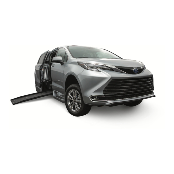
- Page 1 Side-Entry Power Foldout built on the Hybrid Toyota Sienna Operator’s Manual 512445 Rev A...
- Page 2 ® W ARNING wheelchair accessible vehicle. We design and build each BraunAbility ® vehicle for reliability, quality and safety. Our founder, Ralph Braun, instilled that ethic from day one, and we live by that commitment today.
-
Page 3: Table Of Contents
CONTENTS Warranty and Registration Instructions ....2 Wheelchair Tiedown and Occupant Introduction ..............3 Restraint .............. 28-45 Operation Quick Reference Guide ....... 4, 5 Seat Removal and Installation Features ..............6, 7 Front Seats (General Information) ....46, 47 Safety Precautions ............ 8 Front Seat Base .......... -
Page 4: Warranty And Registration Instructions
WARRANTY AND REGISTRATION Examine your vehicle for any damage. Should any damage have occurred during delivery, notify the carrier at once with any claims. Review the service agreement, delivery checklist and warranty registration form with your sales repre- sentative. The form must be signed by the con- sumer and retailer. -
Page 5: Introduction
INTRODUCTION BraunAbility wheelchair acces- This manual addresses standard If you experience an operation ® sible vehicles are designed to features as well as options. Refer problem or there is any sign of provide mobility independence to the instructions applicable wear, damage, or other abnor- for wheelchair passengers. -
Page 6: Operation Quick Reference Guide
OPERATION QUICK REFERENCE GUIDE Operation Overview Interior mounted control switches display one of DOOR This overview provides a simplified explanation of these graphics. operation. Read the entire manual for complete details. Contact Customer Care at 1-800-488-0359 One-Touch Control Activation if any of this information is not understood. Power door, kneel and ramp functions are activated Power Operation by pressing and releasing a control switch (press and... - Page 7 OPERATION QUICK REFERENCE GUIDE Operating Your Wheel- And the sliding door opens The rear suspension lowers chair Accessible Vehicle Couldn’t Be Simpler . . . The ramp deploys Allowing easy entrance! Just press and hold the remote transmitter passenger slide door button or one of the interior mounted control switches .
-
Page 8: Features
FEATURES Hybrid Vehicle: This wheel- Ramp Access Passenger Side Lowered Floor from Rear Power Slide Door: The control Axle to Toe Pan: This feature chair accessible vehicle is built on a hybrid chassis. Hybrid system activates the passenger provides additional headroom, vehicles utilizes combustion side power slide door for ramp and further reduces the slope... - Page 9 FEATURES Driver Seat: For the wheel- See Figure 1 for anchorage point locations and wheelchair mount- chair occupant who chooses Front Position ing positions (Positions B and C). to drive, this seat (Position A) “L” Track can be removed and adaptive One Forward-Facing Wheelchair driving systems custom tai- Tiedown and Occupant Restraint...
-
Page 10: Safety Precautions
SAFETY PRECAUTIONS Safety Symbols SAFETY FIRST! Know That..All information contained in this manual and supplements (if included), is provided for your safety. Familiarity with proper operation instructions as well as proper maintenance procedures are necessary to ensure safe, trouble-free operation. Safety precautions are provided to identify potentially hazardous situations and provide instruction on how to avoid them. -
Page 11: Operation
Do not attempt to interface after- of the vehicle and the power market controls without authori- Terminology door closes. zation from BraunAbility. To do so may result in serious bodily “Kneeling” is the lowering mo- Control System injury and/or property damage. -
Page 12: 12V Accessory Battery
OPERATION 12V Accessory Battery Guidelines for Charge Retention Battery Maintenance Guidelines General Information 12V Accessory Battery & Recharging Hybrid vehicles rely on the HV Items that will help prevent 12V In case of 12V accessory battery System (HV battery, HV inver- accessory battery drain, when not charge loss, adhere to all OEM tor, and HV generator) to provide... - Page 13 INTENTIONAL BLANK PAGE Page 11...
-
Page 14: Control Switches
OPERATION Control Switches Remote Keyless Entry Remote Keyless Entry Transmitter Transmitter w/Power Hatch Power door, kneel and ramp functions can be activated Using the OEM remote entry Using the OEM remote entry using the OEM remote keyless transmitter eliminates the need transmitter eliminates the need entry transmitter or one of the for an additional remote control. - Page 15 OPERATION Dash Switch B-Pillar Switch C-Pillar Switch A switch is located on the wall A switch is located on the wall For front seat passengers, a panel ahead of the passenger panel behind the passenger control switch is located on the slide door (B-Pillar).
- Page 16 OPERATION Overhead Console Switch For front seat passengers, a control switch is located in the overhead console. Press and hold switch displaying side door graphic. Page 14...
- Page 17 OPERATION Sliding Door Main Switch Ramp/Kneel On/Off Switch The ramp access power door is active at all times. When driving The sliding door main switch The ramp/kneel on/off switch is the vehicle and use of the ramp is located on the driver lower located on the center console is not required, the ramp can be left knee bolster.
-
Page 18: Ramp Access Sliding Door
OPERATION Ramp Access Sliding Door Note: If a control switch is Keep clear of the area in which pressed or the outside door the power door operates. Ensure Press and hold the remote handle is pulled while the power door travel path is clear. Per- keyless entry transmitter or sliding door is opening or clos- sonal injury or property damage... - Page 19 OPERATION Power Door Manual Operation The passenger side power sliding door can be operated manually. Unlock the passenger sliding door and put the Main switch in the Off position. Open the slide door from inside or outside using the OEM door handles. Always open the door smoothly.
-
Page 20: Kneel System
OPERATION Automatic Kneel System Kneel On/Off Feature Do not leave your vehicle in the kneeled (lowered) position for Kneeling is the lowering motion of A kneel on/off feature is incor- extended periods of time. the electrohydraulic rear suspen- porated in the electronic control sion. -
Page 21: Kneel Electrical Override
OPERATION Kneel Electrical Override Note: Override switches are Kneel Override Switch provided as a backup. The An electrical override feature electronic control system is the ELECTRICAL OVERRIDE is incorporated in the kneel recommend/primary control system. The override by-passes method for mobility functions KNEEL RAMP the electronic control system to... -
Page 22: Power Ramp Operation
OPERATION Power Ramp Operation Ramp On/Off Feature motor will stop running. Activating a control switch again will start or The term “deploy” indicates the A ramp on/off feature is incorpo- resume the Close functions (ramp extending (outward) motion of rated in the vehicle control sys- will stow, vehicle will raise and the the ramp to the deployed posi- tem. -
Page 23: Ramp Electrical Override
OPERATION Ramp Electrical Override nearly horizontal position (ap- Note: Override switches are pro- proximately 6”- 8” above ground vided as a backup. The electron- level). The ramp continues to An electrical override feature is in- ic control system is the recom- corporated in the power ramp sys- slowly lower the remaining dis- mend/primary control method for... -
Page 24: Power Ramp Safety
OPERATION Power Ramp Safety W ARNING Be certain there is adequate clearance outside the vehicle before deploying the power ramp. Keep clear Keep clear of of area in which the ramp operates. Be certain no area in which person or obstruction is within the path of the ramp ramp operates. -
Page 25: Power Ramp Manual Operation
OPERATION Power Ramp Manual Operation Do not release the ramp when the vehicle only if an assistant manually deploying or stowing is not available and it is abso- The power ramp can be manu- the ramp. The ramp will free-fall. lutely necessary (power failure). -
Page 26: Ramp Passenger Safety
OPERATION Ramp Passenger Safety Never board the ramp if you or your attendant are intoxicated. The wheelchair should be positioned Wheelchair passengers and attendants (when ap- in the center of the ramp at all times. You must be plicable), must use basic common sense and good able to clearly view the ramp whenever boarding and judgment regarding ramp safety. - Page 27 OPERATION as specified by the manufacturer, W ARNING before loading onto a wheelchair ramp. Be aware of Different types of disabilities require ramp slope. different types of wheelchairs and different types of wheelchair- equipped occupant restraint belt systems (torso restraint). It is the responsibility of the wheelchair pas- senger to have his or her wheel- chair equipped with an occupant restraint (seat belt)
- Page 28 OPERATION Wheelchair Orientation and Securement During The aid of an attendant stabilizing the wheelchair is Transport: The wheelchair and occupant must face recommended for optimum safety. Wheelchair pas- sengers who intend to enter and exit the vehicle with- the front of the vehicle and must be secured using out the assistance of an attendant must determine the Forward-Facing Wheelchair Tiedown and Oc- the safest and most practical method and orientation...
- Page 29 INTENTIONAL BLANK PAGE Page 27...
-
Page 30: Wheelchair Tiedown And Occupant Restraint
WHEELCHAIR TIEDOWN AND OCCUPANT RESTRAINT Terminology Forward-Facing Wheelchair Note: Wheelchair capacity may Tiedown and Occupant be limited based on the dimen- While many of the terms are self Restraint System: sions of specific wheelchairs explanatory, several have been and vehicle payload capacity. specifically developed to clarify Floor track (anchor points) terminology which is unique to... - Page 31 WHEELCHAIR TIEDOWN AND OCCUPANT RESTRAINT Driver Seat: This seat (Position Refer to the following guide- A) can be removed and adaptive lines, illustrations, photos and Front Position driving systems custom tailored instructions for proper use of “L” Track for the driving wheelchair oc- the belt and track restraint cupant can be purchased from system.
- Page 32 WHEELCHAIR TIEDOWN AND OCCUPANT RESTRAINT Wheelchair Tiedown Occupant Restraint Over-Center Straps (four supplied) Four adjustable over-center Lap and shoulder belts should bear upon buckle straps are provided for se- the bony structure of the body and should be curement of the wheelchair (two worn low across the front of the pelvis with the for the front and two for the rear).
- Page 33 WHEELCHAIR TIEDOWN AND OCCUPANT RESTRAINT Occupant Restraint Adjustable Rigid Lap Belt Lap Belt Extension Extension OEM Lap and Shoulder Belt Operate the OEM lap and shoul- (supplied) (optional) der belt as instructed in your One adjustable lap belt extension is OEM owner’s manual.
- Page 34 WHEELCHAIR TIEDOWN AND OCCUPANT RESTRAINT Occupant Restraint 2-Piece Waist Chest (Lap) Belt (Shoulder) Multi-Piece Chest & Waist Belt with a lap belt attachment (pin (female) (male) Belt fitting connector). See photo on The multi-piece chest and waist page 30. Connect the lap belt belt assembly provides separate slotted fitting to the mating pin lap and shoulder belts that can be...
- Page 35 WHEELCHAIR TIEDOWN AND OCCUPANT RESTRAINT Strap, Belt and Track Maintenance Connect the adjustable shoulder Inspect strap and belt assemblies fre- No product developed belt upper pin fitting to the wall- quently. Any damage such as strap/ to date can guarantee mounted shoulder belt adaptor belt cuts, fraying or malfunctioning call successful securement...
- Page 36 WHEELCHAIR TIEDOWN AND OCCUPANT RESTRAINT Tiedown Strap Angles Wheelchair Reference Plane Locate wheelchair in forward-facing position center- Rear ing wheelchair squarely within “L” track. The front Securement and rear straps, when attached, should create angles Points approximately as shown in Figure 3. Preferred angles and locations of straps from wheelchair se- 30°...
- Page 37 WHEELCHAIR TIEDOWN AND OCCUPANT RESTRAINT Keeper Fitting and “L” Track a. Push down Attachment Instructions on keeper. To Engage Keeper Fitting: Keeper 1. Insert keeper fitting into track (align engagement feet with holes in L- Track). See Figure A. L-Track 2.
- Page 38 WHEELCHAIR TIEDOWN AND OCCUPANT RESTRAINT Over-Center Strap Attachments Wheelchair Tiedown Figure 4 1. Place wheelchair facing forward in securement area. Apply Strap Release: Push to release tension on strap (open buckle). wheel brakes or turn power off. 2. Attach the four tiedown hooks Over-Center to solid frame members or Strap...
- Page 39 WHEELCHAIR TIEDOWN AND OCCUPANT RESTRAINT Wheelchair Tiedown Velcro b. Close 4. With buckle open, pull loose end of strap until tight (see Figure G). Velcro While holding the loose end with one hand, close the buckle until it locks. a. Pull See Figures G and I.
- Page 40 WHEELCHAIR TIEDOWN AND OCCUPANT RESTRAINT OEM Upper Torso Lap Over-center and Shoulder Belt Buckle Strap Figure 5 Keeper Lap and Shoulder Belt “L” Track Over-center Lap Belt Ex- Buckle Strap tensions: An FORWARD adjustable lap FACING “L” Track belt extension is supplied (shown in Figures 5, 6 and 7).
- Page 41 WHEELCHAIR TIEDOWN AND OCCUPANT RESTRAINT Figure 6 OEM Upper Note: Generic seat position shown. Attachment procedures Torso Lap FORWARD are identical for all positions. and Shoulder FACING Belt Lap and Shoulder Belt Keeper attachment details are provided Adjustable on page 35. Lap Belt Extension Keeper...
- Page 42 WHEELCHAIR TIEDOWN AND OCCUPANT RESTRAINT Occupant Restraint Figure 7 Lap and Shoulder FORWARD FACING Belt Page 40...
- Page 43 WHEELCHAIR TIEDOWN AND OCCUPANT RESTRAINT Occupant Restraint Note: OEM lap / shoulder belts serve as both window-side lap belt and shoulder belt. OEM Lap and Shoulder Belt: OEM lap and shoul- 3. Occupant Restraint - Ensure belts are adjusted der belts are addressed on pages 38-41. Refer to pages 42-45 for multi-piece chest and waist belts.
- Page 44 WHEELCHAIR TIEDOWN AND OCCUPANT RESTRAINT Over-center Shoulder Shoulder Belt Buckle Strap Figure 8 Belt Adaptor Keeper Multi-Piece Chest and Over-center Waist Belts Buckle Strap “L” Track Lap Belt Integrated FORWARD with Occupant Lap and FACING “L” Track Buckle Restraint Belts Shoulder Belt: with Pin Fitting Multi-piece...
- Page 45 WHEELCHAIR TIEDOWN AND OCCUPANT RESTRAINT Figure 9 Note: Generic seat position shown. Attachment procedures FORWARD Multi-Piece are identical for all positions. Shoulder Belt FACING Adaptor Chest and Waist Belts Lap Belt Keeper attachment with Female details are provided Shoulder Receptacle on page 35.
- Page 46 WHEELCHAIR TIEDOWN AND OCCUPANT RESTRAINT Occupant Restraint Multi-Piece Figure 10 Chest and Waist Belts FORWARD Shoulder Belt FACING Adapter Connection Lap and Shoulder Belt Lap to floor Connections Connections Page 44...
- Page 47 WHEELCHAIR TIEDOWN AND OCCUPANT RESTRAINT Occupant Restraint 2. Attach Shoulder Belt Multi-piece Chest and Waist Belts: Multi-piece a. On the window-side, attach shoulder belt belts are addressed on pages 42-45. Refer to pages pin connector to wall mounted 38-41 for OEM upper torso lap and shoulder belt shoulder belt adapter details.
-
Page 48: Seat Removal And Installation
SEAT REMOVAL AND INSTALLATION SEAT REMOVAL AND INSTALLATION SEAT REMOVAL AND INSTALLATION SEAT REMOVAL AND INSTALLATION Front Seats: In an effort to Driver and passenger side front When positioning seats, it is your produce vehicles that can be seats are equipped with quick- responsibility to reconnect all seat configured to meet a variety of release seat base attachments... - Page 49 SEAT REMOVAL AND INSTALLATION Front Seat Adjustable Cup Do not use a floor mat at the front driver seat position when Holders: Driver and Passenger the conversion seat is installed. front seats are equipped with cup Connect front seat Improperly fitted and/or secured holders.
-
Page 50: Front Seat Base
SEAT REMOVAL AND INSTALLATION SEAT REMOVAL AND INSTALLATION SEAT REMOVAL AND INSTALLATION SEAT REMOVAL AND INSTALLATION Front Seat Bases (General) Figure 11 Seat Quick-release seat base (riser) at- Passenger Side Front tachments engage recessed floor Seat and Seat strikers. A foot-activated release Base (Riser) pedal is located at the rear of the seat base. -
Page 51: Seat Electrical Harnesses
SEAT REMOVAL AND INSTALLATION Snap-in Seat Connectors Figure 12 Alignment Front seat wiring harnesses are Seat Harness Slot Plug and equipped with a push button re- Receptacle lease snap-in connector (plug). Operate connectors as detailed here. See pages 50 and 51 for Alignment the location of the harness plug, B-Pillar receptacle and storage... - Page 52 SEAT REMOVAL AND INSTALLATION SEAT REMOVAL AND INSTALLATION SEAT REMOVAL AND INSTALLATION SEAT REMOVAL AND INSTALLATION Front Seat Wiring Harness & Passenger side front Figure 13 B-Pillar Receptacle seat base (riser) shown without seat for clarity. Seat Harness B-Pillar An electrical harness receptacle Connection is located to the rear of each seat base in the wall (at “B”...
- Page 53 SEAT REMOVAL AND INSTALLATION Harnesses Seat Base Storage Passenger side front Figure 14 seat base (riser) shown Receptacle without seat for clarity. Seat Harness Storage When seats are removed, the seat Connection electrical harness plug must be connected to the storage recep- tacle provided in the seat base.
-
Page 54: Front Seat Removal
SEAT REMOVAL AND INSTALLATION SEAT REMOVAL AND INSTALLATION SEAT REMOVAL AND INSTALLATION SEAT REMOVAL AND INSTALLATION Front Seat Bases (Removal) Front Seat Removal Instructions 1. Move seat to full forward and Quick-release seat base (riser) attachments engage recessed upright position. floor strikers. - Page 55 SEAT REMOVAL AND INSTALLATION Stowed Seat Base Release Pedal Deployed Front Wheels Deployed Rear Wheels Illustrations depict seat base only. Stowed Depress Depress pedal (a) Pull seat up and back, Seat Base pedal. and lift seat (b). roll seat out of vehicle. Engaged Strikers Deployed Rear Wheels Deployed Front Wheels...
-
Page 56: Front Seat Installation
SEAT REMOVAL AND INSTALLATION SEAT REMOVAL AND INSTALLATION SEAT REMOVAL AND INSTALLATION SEAT REMOVAL AND INSTALLATION Front Seat Bases (Installation) Front Seat Installation Instructions Quick-release seat base (riser) 1. Roll seat base into position, just attachments engage recessed behind the floor mounted strikers. floor strikers. - Page 57 SEAT REMOVAL AND INSTALLATION Stowed Roll seat (locked) into position. Seat Base Floor Strikers Engaged Front Engagement Engaged Strikers Strikers Pedal Roll seat into position. Engage front strikers (a) and Stowed (locked) depress engagement pedal (b). Seat Base Floor Strikers Engaged Front Strikers Engaged Strikers Page 55...
-
Page 58: Third Row Seats
SEAT REMOVAL AND INSTALLATION SEAT REMOVAL AND INSTALLATION SEAT REMOVAL AND INSTALLATION SEAT REMOVAL AND INSTALLATION Third Row Seats Third Row Seat Removal: Third row 60/40 split bench seats 60/40 seat removal procedures are the Seats backs must have been modified during con- same. - Page 59 SEAT REMOVAL AND INSTALLATION 60/40 Third Row Seats Seat Head Rest Handle Seat Back Seat Strap Seat Stow in Floor Seat Back (Unavailable) Strap Seat Harnesses Seat Stow in Floor Floor (Unavailable) Strikers Page 57...
-
Page 60: Third Row Seat Footrest
SEAT REMOVAL AND INSTALLATION SEAT REMOVAL AND INSTALLATION SEAT REMOVAL AND INSTALLATION SEAT REMOVAL AND INSTALLATION Third Row Seat Footrest A lighted third row seat footrest is provided to accommodate passenger footing with the Seat Back lowered floor. Strap Deploy footrest (fold down). Third Row Seat Note: The footrest is designed... - Page 61 INTENTIONAL BLANK PAGE Page 59...
-
Page 62: Maintenance
1-800-488- dures will ensure trouble-free and snow. Smooth unobstructed 0359. One of our BraunAbility ® operation and increase the ser- slide door operation is crucial for Customer Care representatives... - Page 63 OEM formed by authorized manufacturer. ing program (MSE certified). service personnel as specified in this Have OEM and BraunAbility Service technicians should be ® manual, maintenance maintenance procedures per- familiar with the lowered floor booklet and applica-...
-
Page 64: Hybrid System Precautions
HYBRID SYSTEM - PRECAUTIONS Hybrid System Features Take care when handling the Never touch, disassemble, hybrid system, as it is a high remove or replace the high Your vehicle is a hybrid vehicle. voltage system (about 650V at voltage parts, cables or their It has characteristics different maximum) as well as contains connectors. - Page 65 HYBRID SYSTEM - PRECAUTIONS Road Accident Cautions If a fluid leak occurs, do not If your vehicle needs to touch the fluid as it may be be towed, do so with four Observe the following precau- strong alkaline electrolyte wheels raised. If the wheels tions to reduce the risk of death from the hybrid battery (trac- connected to the electric...
- Page 66 HYBRID SYSTEM - PRECAUTIONS dumped, and it is hazard- the vehicle may not be aware ous to the environment or of these dangers. Hybrid Battery (Traction someone may touch a high Battery) voltage part, resulting in an If your vehicle is disposed electric shock.
- Page 67 HYBRID SYSTEM - PRECAUTIONS Hybrid System Component Diagram Page 65...
-
Page 68: Hybrid System Maintenance
HYBRID SYSTEM - MAINTENANCE Hybrid Battery (Traction Do not get water or foreign Battery) Air Intake Vents / materials in the air intake Filters Hybrid Battery (Traction vents/filters as this may Battery) Air Intake Vents cause a short circuit and The hybrid battery (traction damage the hybrid battery battery) and hybrid battery air... - Page 69 HYBRID SYSTEM - MAINTENANCE There are filters installed to the air intake vents. When the vents/filters remain noticeably dirty even after cleaning the air intake vents/filters replacement is recommended. See follow- ing pages for filter cleaning or replacement section. If “Maintenance Required for Traction Battery Cooling Parts See Owner’s Manual”...
- Page 70 Replace all (4) vent/filters. from being affected, visually in- Replacement vent/filters are spect the hybrid battery (traction There are (4) air intake vents/fil- available at your BraunAbility battery) air intake vents/filters ters under the third-row seats. dealer. periodically for dust and clogs.
- Page 71 HYBRID SYSTEM - MAINTENANCE Figure 15 Hybrid Battery Air Intake Vents / Filters Component Diagram Service Plug Push Access Hatch Pins Vent / Filter (Removed) Vent / Filter (Installed) Page 69...
- Page 72 If water is by your BraunAbility dealer. cleaning. If a compressed air applied to the hybrid battery blow gun, etc. is used to blow...
- Page 73 HYBRID SYSTEM - MAINTENANCE If “Maintenance Required for Traction Battery Cool- ing Parts See Owner’s Manual” is shown on the Multi-Information Display If the vehicle is continuously driven with the warning mes- sage (indicating that charg- ing/discharging of the hybrid battery [traction battery] may become limited) displayed, the hybrid battery (traction battery)
-
Page 74: Auxiliary Power Supply / Below Floor Obstructions
AUXILIARY POWER SUPPLY / BELOW FLOOR OBSTRUCTIONS Auxiliary Power Supply: Do not Note: The technical informa- Refer to the illustration on page 75 tion provided on pages 72-75 of connect auxiliary devices directly to to avoid contacting or damaging this manual is service related. the vehicle battery. - Page 75 AUXILIARY POWER SUPPLY / BELOW FLOOR OBSTRUCTIONS Fuse Blocks: Two fuse blocks Battery Fuse Block: The total Under Dash Fuse Blocks are provided for use as an aux- maximum load must not exceed iliary power source (one ignition 30 amperes. fuse block and one battery fuse block).
- Page 76 AUXILIARY POWER SUPPLY / BELOW FLOOR OBSTRUCTIONS Below Floor Obstructions Refer to the illustration on the Note: Some wiring harnesses following page when installing shown may not be present. When installing an electrical aftermarket equipment to avoid Avoid all harness locations. tie-down, power seat or other contacting or damaging vital aftermarket electrical device,...
- Page 77 AUXILIARY POWER SUPPLY / BELOW FLOOR OBSTRUCTIONS Page 75...
-
Page 78: Jacking And Tire Changing
JACKING AND TIRE CHANGING Jacking and Tire Changing Refer to the OEM-supplied manual for tire chang- ing instructions and safety precautions, as well as Interior Spare Tire Mount (if Equipped): instructions regarding other roadside emergencies. The spare tire is located inside the rear driver side wall compartment (OEM location). -
Page 79: Towing And Transporting
Aftermarket trailer tow packages are prohibited. Transporting a Lowered Floor Vehicle BraunAbility lowered floor vehicles should be transported on a trailer rather than towed with one set of wheels suspended and the other set of wheels remaining in road contact. -
Page 80: Reporting Safety Defects
National Highway Traffic Safety Admin- BraunAbility istration (NHTSA) in addition to notifying BraunAbility. 631 West 11th Street P.O. Box 310 If NHTSA receives similar complaints, it may open an inves-... - Page 82 ® © 2021 BraunAbility. All rights reserved. All illustrations, descriptions and specifications in this manual are based on the latest product information at the time of publication. The Braun Corporation reserves the right to make changes at any time without notice.
Need help?
Do you have a question about the Side-Entry Power Foldout built on the Hybrid Toyota Sienna and is the answer not in the manual?
Questions and answers