
Subscribe to Our Youtube Channel
Related Manuals for Pro Spot i5


Summary of Contents for Pro Spot i5
- Page 1 Resistance Spot Welder Instruction Manual MNL-i5-1.3 Version 1.1 All Info Copyright © Pro Spot International Inc.
- Page 2 We have a great customer service re- cord, we intend to keep it that way. Pro Spot is certified by CASE and a member of the ICAR Industry Training Alliance Contact Information Pro Spot International, Inc. U.S.A.
- Page 3 Come to my.prospot.com and register today! Gain access to exclusive product demonstration videos, training, important product documents, and more. My Pro Spot is a site just for you with an easy to use interface that is custom tailored based on the products you own. This means quicker troubleshooting solutions, with less hassle.
-
Page 4: Table Of Contents
4.2.3 i5 Touch Screen Control........ -
Page 5: Quick Start Instructions
WARNING! Read this manual in it’s entirety before attempting to weld with the i5 for the first time. Before turning the welder on, make sure it is connected to the proper electricity by certified professionals. The water tank should be filled with a 50/50 water & antifreeze solution, and make sure to properly secure all water hoses. -
Page 6: Introduction
You have a welder and support group that will increase your productivity. The integrated features, ease of use, speed and quality welds that your i5 offers will become an important part of your business. The following information will be needed when you call Pro Spot:... -
Page 7: Safety
40º C has been determined by simulation. 2.1 General The i5 Spot welder has been designed and is tested to meet strict safety require- ments. Please read the following instructions carefully before operating the i5 and refer to them as needed to ensure the continued safe operation of the welder. - Page 8 WARNING! All service and maintenance ATTENTION! Tout le service et l'entretien doivent être must be carried out by Pro Spot service effectués par personnel et soutien de service Pro personnel and service support. Risk for Spot.
-
Page 9: Safety Devices 2.3.1 Cooling
IMPORTANT! Turn the power off before disconnecting water hoses from the weld gun. IMPORTANT! Make sure the water cooling hoses are securely clipped into place before welding. IMPORTANT! The i5 welder comes without coolant to ease transportation, be sure to fill coolant tank before turning on the welder! IMPORTANT! If the thermal breaker has switched off the welder, please contact Pro Spot’s authorized service personnel... -
Page 10: Installation
Check the i5 Spot Welder carefully to make sure that no damage has occurred during transport. If anything is damaged or missing, the welder may be unsafe to use until the part is repaired or replaced. -
Page 11: Connection Of Electrical Supply
The i5 Spot welder must be connected to a pneumatic air network. (100 PSI to 130 PSI) 1. Connect the i5 to the air supply via the threaded input port at the rear of the welder using a standard connector. -
Page 12: Before You Begin Welding 4.1.1 Calibration
WELD PROGRAM: Maintaining the air pressure after the current shuts off makes the weld cool down under pressure resulting in a harder, stronger weld. This fea- ture is built in to the i5's weld control program and is engaged automatically dur- ing a weld cycle. -
Page 13: About Your Welder
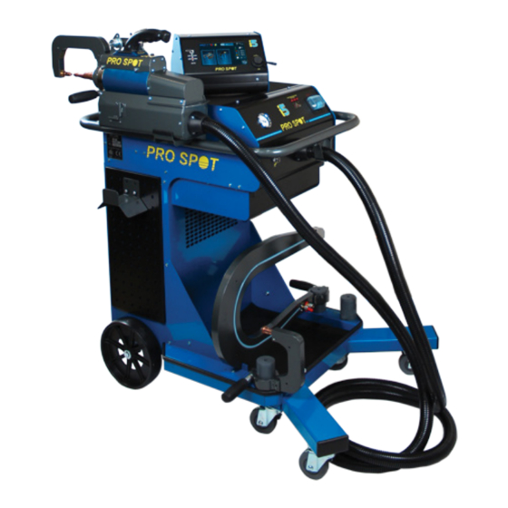
Air Pressure Fuses Gauge Gun Trigger Input for Single Sided Adapter Cooling Fan Air Hose Input Power Cord Coolant Tank Coolant Level Indicator Figure 4.1 i5-Front View Figure 4.2 i5-Back View All Info Copyright © Pro Spot International Inc. Page 11... -
Page 14: Turning On The Welder
Verify this before turning on the power. Switch the circuit breaker on the front panel to “ON”. 2. The display will go through the start-up procedure. 3. The i5 is now ready to use. IMPORTANT! Make sure to read the instruction manual before operating the welder. - Page 15 4.2.3 i5 Login and User Log Starting Up When the i5 is turned on the user is presented with a Enter the user password to begin welding with that login screen. Select the desired user name or space user or the administrator password to modify, add, or where a new user is to be added.
-
Page 16: I5 Touch Screen Control
• Welder Calibration to navigate to Semi-Auto and • Brightness Control Manual modes. • Factory Default Global Settings Screen Accessed from the Status Screen (as pictured above). 4 - Operation All Info Copyright © Pro Spot International Inc. Page 12... - Page 17 Press the “open gun” button to release the pressure gauge. Continued on next page > 4 - Operation All Info Copyright © Pro Spot International Inc. Page 12...
- Page 18 All of the welds can be viewed by navigating with the up and down Use the log navigation button to arrows. enter a specific weld number. 4 - Operation All Info Copyright © Pro Spot International Inc. Page 12...
- Page 19 Select parameters to reset to Set the date and time, and change manufacture settings, then hit the time formatting. reset button. View software version details. 4 - Operation All Info Copyright © Pro Spot International Inc. Page 12...
- Page 20 IMPORTANT! Turn the power off before disconnecting water hoses from the weld gun. IMPORTANT! Make sure the water cooling hoses are securely clipped into place before welding. IMPORTANT! The i5 welder comes without coolant to ease transportation, be sure to fill coolant tank before turning on the welder! IMPORTANT! If the thermal breaker has switched off the welder, please contact Pro Spot’s authorized service personnel...
- Page 21 WARNING: Measurement Only Mode: The caliper icon sets the i5 to measurement only mode. While in measurement only mode the caliper icon will be highlighted green. Measurement only mode allows you to measure the thickness and resistance of steel without welding it.
- Page 22 Each colored stack represents a piece of metal in the stack and the lines in between each piece of metal repre- sents the surface condition. 4 - Operation All Info Copyright © Pro Spot International Inc. Page 14...
- Page 23 Flat 1/2” Cap PS-027 OEM Cap Then select a weld program to over-write. Go to settings to edit the stack composition and surface conditions. Continued on next page > 4 - Operation All Info Copyright © Pro Spot International Inc. Page 14...
- Page 24 Enter the thickness of the material and press the green check mark. Press the surface condition button to cycle through several different surface scenarios. 4 - Operation All Info Copyright © Pro Spot International Inc. Page 14...
- Page 25 IMPORTANT! Turn the power off before disconnecting water hoses from the weld gun. IMPORTANT! Make sure the water cooling hoses are securely clipped into place before welding. IMPORTANT! The i5 welder comes without coolant to ease transportation, be sure to fill coolant tank before turning on the welder! IMPORTANT! If the thermal breaker has switched off the welder, please contact Pro Spot’s authorized service personnel...
- Page 26 Some basic settings will be displayed on the main Manual Mode Screen. What settings are available are depen- dant on which weld type is selected. 4 - Operation All Info Copyright © Pro Spot International Inc. Page 14...
- Page 27 Double Weld Pulse Weld A single weld. Two consecutive 3-9 consecutive current pulses. current pulses. Then select a weld program to over-write. Continued on next page > 4 - Operation All Info Copyright © Pro Spot International Inc. Page 14...
- Page 28 Pulse Pulse Off Count Delay Amount of time between Number of pulses that are applied each pulse. (between 3 and 9) 4 - Operation All Info Copyright © Pro Spot International Inc. Page 14...
- Page 29 0 during the weld during the during the first pulse. second pulse. Weld Delay Amount of time between pulses. Continued on next page > 4 - Operation All Info Copyright © Pro Spot International Inc. Page 14...
- Page 30 Auto Weld screen automatically. If there was a problem with the weld, the status screen will display what went wrong. Press the red X button to continue. 4 - Operation All Info Copyright © Pro Spot International Inc. Page 14...
- Page 31 The navigation bar helps to visually establish which weld program is currently selected. Weld duration and current can be modified from the main screen. 4 - Operation All Info Copyright © Pro Spot International Inc. Page 14...
- Page 32 Nail Dent Pulling Washer Dent Pulling PS-870 CLT-29 Contact Carbon Shrinking Shrinking PS-870 Rivet Welding Then select a weld program, each tip has 16 different pre-set weld programs. 4 - Operation All Info Copyright © Pro Spot International Inc. Page 14...
- Page 33 4.2.5 Service Panel Window – Control System Status Lamps Location: Underneath the i5’s swivel head that houses the display screen. Purpose: To quickly determine the status of many internal systems.The welder needs to be powered up. There are several lights to watch for. The Voltage Indicator windows...
-
Page 34: Double-Sided Welding Settings
Figure 5.1 SA-0053 Spot Gun - Component Diagram 5.1.2 Using the Double-Acting Gun Push this button to open electrodes wide. Push this button to close electrodes and weld. 5 - Double-Sided Welding All Info Copyright © Pro Spot International Inc. Page 17... -
Page 35: Extension Arms
5.2 Extension Arms The Pro Spot i5 comes with a variety of extension arms to accomodate most welding job situations. Please refer to fig. 5.3 for details on what welding electrodes to use with each extension arm. NOTE: Extension arms marked “optional” are available from your local distributor or online at www.prospot.com... - Page 36 REMARQUE: PS-027 caps de soudure peuvent être achetés en paquets de 15 à partir de votre distributeur local ou en ligne à www.prospot.com 5 - Double-Sided Welding All Info Copyright © Pro Spot International Inc. Page 19...
-
Page 37: Ps-500 Electrode Alignment
IMPORTANT! Toujours maintenir l'alignement des électrodes appro- priées. Ne pas le faire peut conduire aux soudures faibles de qualité inférieure! 5 - Double-Sided Welding All Info Copyright © Pro Spot International Inc. Page 20... -
Page 38: Removing Welding Electrodes
Grip the handles and twist them in opposite directions. 2. If twisting the cap and electrode doesn’t work you can gently tap them with a hammer (Pro Spot ALU-9 Aluminum Hammer shown) while maintaining control of the electrode by holding one of the vice grips firmly with one hand. -
Page 39: Welding Electrode Maintenance
The PLT-51 (meant for the OEM weld caps) is distinguishable from the PLT-50 by the green mark on the neck of the grinding head. Cap cleaning: After the i5 has been turned off, connect the PLT-51 tip sharpener to a compressed air hose and set the sharpening blade on the weld cap to be cleaned. -
Page 40: Wheel House Arm
M6 X 16 SHCS (52-9029) 90-0420: Wheelhouse Electrode Assembly 60mm Electrode Shank The Wheel House Adapter allows access to hard to reach areas such as the wheel house. 5 - Double-Sided Welding All Info Copyright © Pro Spot International Inc. Page 22... - Page 41 6.1 Single-Sided Welding Adapter A Single Sided welding adapter is available for the i5 Smart Resistance Spot Welder. Quickly and easily attach a single-sided dent puller to the i5’s electrodes and plug into the control panel. The i5’s built in soft-...
- Page 42 NOTES...
- Page 43 NOTES...
- Page 44 5932 Sea Otter Place Carlsbad, CA 92010 Toll Free (US Only): (877) PRO SPOT Phone: (760) 407-1414 Fax: (760) 407-1421 E-mail: info@prospot.com Web: www.prospot.com All Info Copyright © Pro Spot International Inc. CAUTION: CAUTION: CAUTION: CAUTION: CAUTION: CAUTION: Always wear eye...
Need help?
Do you have a question about the i5 and is the answer not in the manual?
Questions and answers