Table of Contents
Advertisement
Advertisement
Table of Contents

Related Manuals for Pro Spot i4s


Summary of Contents for Pro Spot i4s
- Page 1 Resistance Spot Welder Instruction Manual MNL-i4s-v1.5...
- Page 2 Pro Spot owns three patents for special welding equipment and applications, and works with the largest auto manufacturers in the world. Pro Spot is a proud ‘MADE IN THE USA’ manufacturer in Carlsbad, CA. The turnkey facility includes Design, Engineering, Machine and Sheet Metal Shops, Powder Coating, Assembly, Training and Customer Support.
- Page 3 My.prospot.com is a site just for you with an easy to use interface that is custom tailored based on the products you own. This means quicker troubleshooting solutions, with less hassle. My Pro Spot is constantly evolving and we have more exciting features to come.
-
Page 4: Table Of Contents
6.0 Single-Sided Welding ................36 6.1 Single-Sided Welding Menu Guide ............37 7.0 i4s Weld Gun .................... 38 7.1 i4s On Gun Screen & Gun Controls ............39 7.2 Extension Arms ..................41 7.3 Electrode Components ................42 8.0 Electrode Alignment, Removal & Maintenance ........43 8.1 Removing Welding Electrodes ............... -
Page 5: I4S Quick Start Instructions
Quick Start Instructions WARNING! Read this manual in its entirety before attempting to weld with the i4s. Before turning on the ma- System Checks and Power On Weld Gun Check Verify the presence of air pressure. Verify that the hoses are secure in place. -
Page 6: Introduction
With the i4s and its connected support system, you will experience a rapid increase in productivity. The integrated and user friendly features, paired with superior speed and overall weld quality will quickly make the i4s a vital element of your business. -
Page 7: Safety
2.0 Safety The i4s Spot Welder is designed for indoor use - Protection Degree IP21S.The i4s Spot Welder is designed to oper- ate from -10º C to 40º C. The unit may be stored and transported in an ambient temperature from -20º C to +55º C. -
Page 8: Important Warnings
Risque de choc électrique. IMPORTANT! The i4s welder may only be used IMPORTANT! Le soudeur i4s peut seulement être welder must be educated in spot welding, colli- sion repair and proper usage of the unit. -
Page 9: Cooling System
IMPORTANT! Turn off the power to the water pump before disconnecting water hoses from the weld gun. IMPORTANT! The i4s welder comes without coolant to ease transportation, be sure IMPORTANT! If the thermal breaker has switched off the welder, please contact Pro Spot’s authorized service personnel. -
Page 10: Installation
3.0 Installation General The i4s Spot Welder is inspected and tested prior to leaving the factory to guarantee consistent quality and the highest possible reliability. Follow the installation tips and operating instructions below to ensure user safety and proper welder performance. -
Page 11: Connecting The Electrical Supply
ATTENTION! Toutes les connexions électriques doivent être faites par un électricien qual- 1. Connect the green wire to ground. Note: Make sure that the supply cable is at least 6 AWG at 208V and 400V. The i4s is rated for over voltage category III and pollution degree 3. -
Page 12: Operation
Squeeze Force: The i4s double-sided gun contains an air cylinder that is capable of compressing the weld caps against the weld stack up to 1000 lbs. In Auto Mode, the i4s automatically adjusts the squeeze force to maximize fusion of ma- terials and minimize expulsion during the welding. -
Page 13: About Your Welder
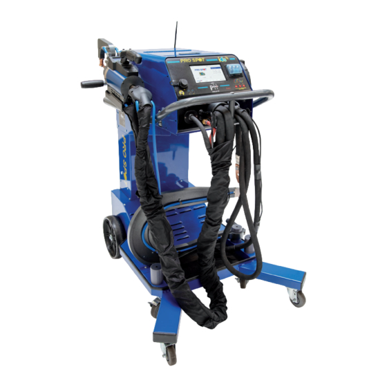
Forward Air Single-Sided Command Cable Pump Motor Fuses Double-Sided Command Cable Water Send Reverse Air Water Return Input Air Regulator Wraparound Handle Coolant Level Indicator Arm Storage Compartment Figure 4.3 i4s-Back View Figure 4.2 i4s-Front View 4.2 About Your Welder... -
Page 14: Turning On The I4S
Only trained personnel should use this welder. IMPORTANT! Assurez-vous de lire le Mode d’Emploi avant d’opérer le WARNING! READ THE FOLLOWING BEFORE WELDING When in use - the i4s discharges a large Some parts of the welder may become hot after prolonged use. -
Page 15: How To Login
(Figure 4.6). Figure 4.6 Enter the user password, then press the green check mark to continue to the i4s Home Screen (Figure 4.7). NOTE: Default user password is - 1234 Figure 4.7 4.4 How To Login... -
Page 16: I4S Home Screen
4.5 i4s Home Screen Home Auto Welding Manual Welding Single-Sided Settings Menu Button Menu Menu Welding Menu Figure 4.8 System Updates Cooling Settings Home Screen Time & Date WIFI Menu Button Training Help Menu Menu Menu System Updates Work Order... -
Page 17: I4S General Settings Menus
4.6 i4s General Settings Menus To access the i4s System Settings Menu, select the Settings tab on the top right of the screen (Figure 4.10). Figure 4.10 WIFI Menu The WIFI Menu will let you connect to any wireless network available in your area. - Page 18 Cooling Menu will turn on automatically once the machine reaches a certain temperature. The Single Sided Air slider turns the air for single sided welding on or off. The Double Sided Air slider turns the air for double sided welding on or off. The Water Pump button turns the water pump on or off.
- Page 19 Date & Time Menu The Date & Time Menu allows the user to set the time and date. It also allows the user to choose whether they wish to see a 12 Hour or 24 Hour Clock display by selecting the Change Display Unit button (Figure 4.15). Figure 4.15 Brightness Menu The Brightness Menu allows the user to select the brightness level of the LCD screen with a range between 20-100...
- Page 20 My Account Menu Change Password Menu Figure 4.17 Preferences Menu In the Display Units Menu you are able to change the way the machine displays temperature, Celsius or Fahrenheit, and the clock settings, 12 Hour or 24 Hour (Figure 4.18). Figure 4.18...
- Page 21 Version Info Menu The Version Info Menu displays the hardware versions the machine has. This information may be useful when looking to see if your machine is up to date (Figure 4.19). Figure 4.19 System Updates Menu The System Update Menu allows you to check for software updates and to download the latest updates from Pro Spot.
-
Page 22: Administration Settings Menus
4.7 i4s Administration Settings Menus To access the Administration Settings: 1. Select the Settings tab. 2. Once you’re on the Setting tab, select Administration (Figure 4.21). 3. Once you see the Administration Menu, you will be prompted with a password screen (Figure 4.22). - Page 23 ADMIN: Work Orders The Work Orders Menu allows you to create work orders which correspond to each individual job. While a work order . After creating a work order, it can be assigned to a technician. Once it has been assigned, it will pop up when that technician logs in. When you export the work order, all of the weld information will come with it.
- Page 24 Figure 4.26 Make A Work Order Active: Make A Work Order Active: Once work orders are assigned to a particular user login, the user would login with their username and then press the W.O. button in the lower status bar. Ther user will be presented with a list of work orders including the default work order.
- Page 25 Export A Work Order: Once the work order has been completed, the information can be exported via Email or USB. 1. Select the work order you wish to export from the Work Order Menu and press Export in the top-right. 2.
- Page 26 Figure 4.30 Figure 4.31 Figure 4.32...
- Page 27 ADMIN: User Menu In the User Menu, the Administrator can add, edit and remove Add A New User: 1. Navigate to the User Menu and select the red Create User Button in the bottom right (Figure 4.33). 2. Once you select Create User, a new user prompt will pop up and ask you for the New User details (Figure 4.34). 3.
- Page 28 Alerts Menu The Alerts Menu allows users to adjust the Current Tolerance, Idle Line Voltage and Weld Line Voltage (Figure 4.36). Figure 4.36 Factory Reset Menu The Factory Reset Menu will give you the option to reset weld programs, user preferences, system alerts and a complete factory reset (Figure 4.37).
- Page 29 Figure 4.38 WARNING! These functions are for factory calibration only and should not be used by anyone other than authorized Pro Spot personnel. Voltage Calibration The Voltage Calibration will help users measure the AC voltage between phases with a multimeter. This should only be performed by authorized Pro Spot personnel.
-
Page 30: Double Sided Welding Programs
5.0 Double Sided Welding Programs Auto Mode on the i4s automatically detects the thickness and resistance of the weld stack up. Once properly calibrated, the user only needs to press and hold the weld trigger and the top right button on the gun and the i4s will determine the correct power levels and duration. -
Page 31: Double Sided Welding Menu Guide
7. Auto Weld Advanced Settings - This button allows the user to change the parameters that affect Auto Mode. You will need the admin password in order to access these settings. WARNING: Contact Pro Spot technical support before modifying any of these settings. -
Page 32: Auto Mode Calibration
Weld Mode settings. Measurement Only Mode: The Caliper icon sets the i4s to Measurement Only Mode. While in Measurement Only Mode, the Caliper icon will be highlighted in green. Measurement Only Mode allows you to measure the thickness and resistance of steel without welding it. -
Page 33: Double Sided Welding Manual Mode
5.4 Manual Mode Welding Menu Guide Figure 5.4 1. Weld Thickness - This button provides selection of 6 different weld thickness (0.7, 1.0, 1.2, 1.5, 2.0, 2.5 mm). The thickness setting is chosen by the thickest layer in your weld stackup. Remember: Satisfactory weld set- tings are always determined by vehicle OEM instructions and destructive testing. -
Page 34: Manual Mode Welding Menu Guide
9. Manual Weld Advanced Settings - This button allows the user to change Squeeze Time, Hold Time, Rise Time, and Fall Time. You will need the Administrator password in order to access this setting. Squeeze Time: The amount of time between when the weld trigger is pressed and held and when the weld current is provided. - Page 35 5.5 Double Sided Welding Manual Mode Manual Mode is for users that want complete control over their weld settings. Manual Mode comes with 16 pre- loaded common weld programs that can be over written by the user and can be reset in the global settings if necessary (Figure 5.7).
-
Page 36: Manual Mode Welding: Dual Weld Settings
5.6 Manual Mode Welding: Dual Weld Settings When you change the Weld Type from Single to Dual, there are additional parameters available to adjust the weld as shown below. Figure 5.10 1. Preheat Time - This button allows the user to adjust the amount of time the welder applies the Preheat Current. -
Page 37: Manual Mode Welding: Pulse Weld Settings
5.7 Manual Mode Welding: Pulse Weld Settings When you change the Weld Type from Dual to Pulse, there are additional parameters available to adjust the weld as shown below. Figure 5.12 1. On Time - This button allows the user to adjust the amount of time the Weld Current is applied during each pulse repetition. -
Page 38: Creating A Custom Weld
5.8 Creating a Custom Weld How To Create A Custom Weld: 1. From the Weld Material screen, select Custom. Weld Material button gives several different options for pre- sets including an option called Custom which is used to store user presets. Start by selecting Custom for Weld Material. - Page 39 4. Choose The Settings. If you selected Single Weld, you will see the following options: Weld Current How much current is applied during the weld. Weld Weld Force Time Amount of time current is applied How much pressure is applied during the weld.
-
Page 40: Single-Sided Welding
Single Sided (SS) Mode can be used for many different applications in auto repair, such as rust and dent repair. With the i4s, you’re able to access 16 programs associated with each selectable SS weld adapter. 6.1 Single Sided Weld Menu Guide Figure 6.1... -
Page 41: Single-Sided Welding Menu Guide
6.2 Welding in Single Sided Mode 1. Select the desired adapter and program from the Single Sided Adapter Menu (Figure 6.2). NOTE: Each attachment has a preset Program including Weld Time and Weld Power. These can be adjusted by selecting either the Weld Time button or the Weld Power button and inputing the desired amount. Figure 6.2 6.2 Welding in Single-Sided Welding Mode... -
Page 42: I4S Weld Gun
7.0 i4s Weld Gun Double-Acting Spot Gun (Part #: PS-700W) The spot gun is used for Double Sided Welding programs: HSS Galvanized Steel, Mild Steel, Weld Bonding, Boron Steel, Pulse Welding, OEM Required Programs and Cus- tom Programs. Double-Acting Spot Gun Component Diagram... -
Page 43: I4S On Gun Screen & Gun Controls
7.1 i4s On-Gun Screen & Gun Controls The i4s gun has an on-gun screen that can show the user exactly which settings and what kind of welds they are producing. This feature gives users the options to make changes to weld settings directly from the gun without needing to go back to the machine. - Page 44 Gun Weld Feedback Screen The Weld Feedback screen will show up on the i4s screen and the i4s gun screen after a weld has been performed. The Weld Feedback screen indicates to the user if the weld passed or failed. It also displays the Measured Preheat Current and the Measured Weld Current.
-
Page 45: Extension Arms
7.2 Extension Arms The i4s has a variety of extension arms to accommodate most welding applications. NOTE: Extension arms marked “optional” are available through your local distributor or online at www.prospot.com. REMARQUE: Bras d’extension portant la mention «facultatif» sont disponibles à... -
Page 46: Electrode Components
7.3 Electrode Components IMPORTANT! Using incorrect welding electrodes with extension arms may result in weak welds and/or damage to your welder. IMPORTANT! En utilisant des électrodes de soudage inexactes au bras d’ex- tension peut donner des soudures faibles et / ou endommager votre soudeur. PSW-080 SHANK/CAP COMPONENTS 1. -
Page 47: Electrode Alignment, Removal & Maintenance
8.0 Electrode Alignment, Removal & Maintenance The machine must always have the electrodes aligned. Improper alignment of the electrodes can lead to poor welds that will not pass OEM requirements. To adjust the electrode on the machine, use the set screws to set alignment (Figure 1). -
Page 48: Removing Welding Electrodes
Grip the handles and twist them in opposite directions. 2. If twisting the cap and electrode doesn’t work, you can gently tap them with a hammer (Pro Spot ALU-9 Aluminum Hammer shown) while maintaining control of the electrode by holding one of the vice 3. -
Page 49: Welding Electrode Maintenance
Note: The PLT-51 (meant for the OEM weld caps) is distinguishable from the PLT-50 by the lack of green mark on the neck of the grinding head. Cap cleaning: 1. Turn off the i4s. 2. Connect the PLT-51 Tip Sharpen- er to a compressed air hose. - Page 50 9.0 Notes...
- Page 52 Pro Spot International, Inc. 5932 Sea Otter Place Carlsbad, CA 92010 Toll Free (US Only): (877) PRO SPOT Phone: (760) 407-1414 Fax: (760) 407-1421 E-mail: info@prospot.com Web: www.prospot.com...
Need help?
Do you have a question about the i4s and is the answer not in the manual?
Questions and answers