
Subscribe to Our Youtube Channel
Related Manuals for Pro Spot AL-5


Summary of Contents for Pro Spot AL-5
- Page 1 AL-5 Capacitor Discharge Aluminum Dent Pulling System Instruction Manual MNL-AL-5-2.0 All Info Copyright © Pro Spot International Inc.
- Page 2 & development department, a fabrication facility and production lines for the various welders Pro Spot International exports its products worldwide, export sales are managed through our headquarter office. The company owns numerous patents for our ingenious application tools, machines, and procedures.
-
Page 3: Table Of Contents
6.0 ADJUSTING THE ELECTRODE PRESSURE KNOB 7.0 GETTING READY TO WELD 8.0 WELDING INSTRUCTIONS 9.0 IDENTIFYING COMMON ISSUES 10.0 PRO PULL ASSEMBLY INSTRUCTIONS 11.0 WELDER PARTS LIST 12.0 WELDER GUN PARTS LIST WARRANTY REGISTRATION WARRANTY All Info Copyright © Pro Spot International Inc. -
Page 4: Introduction
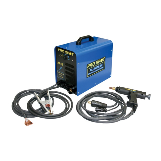
NOTE: You can now order parts online at prospot.com/store/ Pro Spot’s AL-5 Capacitor Discharge Stud Welder is designed for aluminum dent pulling but can also be used with steel studs for welding to UHSS panels with no or very little heat applied to the panels. The welder is very easy to use and is controlled by one knob to adjust weld power. -
Page 5: Safety & Environmental Specifications
2.1 General The AL-5 stud welder has been designed and is tested to meet strict safety requirements. Please read the following instructions carefully before operating the AL-5 and refer to them as needed to ensure the continued safe operation of the welder. - Page 6 WARNING! All service and maintenance ATTENTION! Tout le service et l'entretien doivent être must be carried out by Pro Spot service effectués par personnel et soutien de service Pro personnel and service support. Risk for Spot. Risque de choc électrique.
-
Page 7: Getting Familiar With Your Welder - Read Before Using
(Not Shown) (OH) Input Cable Ground Cable 1 Ground AL-5 Stud Gun Cable 2 Ground Cable 3 Positive Grounding Plate Cable 4 Input Cable Rear View Front Panel Zoom ON / OFF Switch All Info Copyright © Pro Spot International Inc. -
Page 8: Getting Familiar With Your Gun
Getting Familiar With Your Gun Electrode Shaft Stud Electrode Adjustable Electrode Set Screws Pressure Knob Stud Trigger Switch Command Positive Cable Cable For Trigger All Info Copyright © Pro Spot International Inc. -
Page 9: Creating A Proper Ground
Creating A Proper Ground Ground Plate Clean surface, weld a stud using the AL-5. Place the ground plate on top of the stud, use a wing nut or similar to tighten the plate to the panel. The closer the ground to the weld location, the better. -
Page 10: Getting Ready To Weld
Pressure Point Do Not Use The Arc melts the point Base of stud is fused to the panel Setting the Weld Voltage: Stud Diameter Set weld knob to: 60-90 70-110 80-130 All Info Copyright © Pro Spot International Inc. -
Page 11: Welding Instructions
Squeeze and hold trigger. Again, do not apply pressure to gun yet. With trigger still squeezed, apply downward pressure until the gun fires and the weld has been made. All Info Copyright © Pro Spot International Inc. -
Page 12: Identifying Common Issues
3. Point and head of stud touches the surface. BAD! 4. Head of stud touches the surface. BAD! 5. Electrode touches surface. BAD! 6. No point on stud. BAD! Will not work. All Info Copyright © Pro Spot International Inc. -
Page 13: Pro Pull Assembly Instructions
Pro Pull Assembly Instructions 10.0 Step 1 Take the shaft assembly apart as seen below Step 2 Remove the Black handle from the Pro Pull gun as seen below. All Info Copyright © Pro Spot International Inc. - Page 14 As seen below. Step 4 Tighten the large nut to the back of the Pro Pull handle. Hand tightening should be sufficient. As seen below. All Info Copyright © Pro Spot International Inc.
- Page 15 Pro Pull Assembly Instructions 10.0 Step 5 Slide the threaded rod through the main shaft, put the washer on the threaded rod and put the wing nut on as well. As seen below. All Info Copyright © Pro Spot International Inc.
-
Page 16: Welder Parts List
11.0 Welder Parts List All Info Copyright © Pro Spot International Inc. - Page 17 Welder Parts List 11.0 All Info Copyright © Pro Spot International Inc.
-
Page 18: Welder Gun Parts List
12.0 Welder Gun Parts List All Info Copyright © Pro Spot International Inc. -
Page 19: Warranty Registration
Pro Spot’s option of any part or parts, which may prove defective under intended use and service as determined by Pro Spot after said part or parts have been returned to and examined by Pro Spot whose address is 5932 Sea Otter Place, Carlsbad CA 92010. -
Page 20: Warranty
AL-5 WARRANTY CARD 5932 Sea Otter Place Carlsbad CA 92010 USA FAX (760) 407-1421 PHONE (760) 407-1414 All Info Copyright © Pro Spot International Inc. - Page 21 NOTES All Info Copyright © Pro Spot International Inc.
- Page 22 NOTES All Info Copyright © Pro Spot International Inc.
- Page 23 NOTES All Info Copyright © Pro Spot International Inc.
- Page 24 Pro Spot International, Inc. 5932 Sea Otter Place Carlsbad, CA 92010 Toll Free: (877) PRO SPOT Phone: (760) 407-1414 Fax: (760) 407-1421 E-mail: info@prospot.com Web: www.prospot.com Copyright © Pro Spot International, Inc. 2016...
Need help?
Do you have a question about the AL-5 and is the answer not in the manual?
Questions and answers